
Characteristics of Strata Behavior and Differentiated Control of Fully Mechanized Mining Working Face with Abnormal Roof


Abstract
:1. Introduction
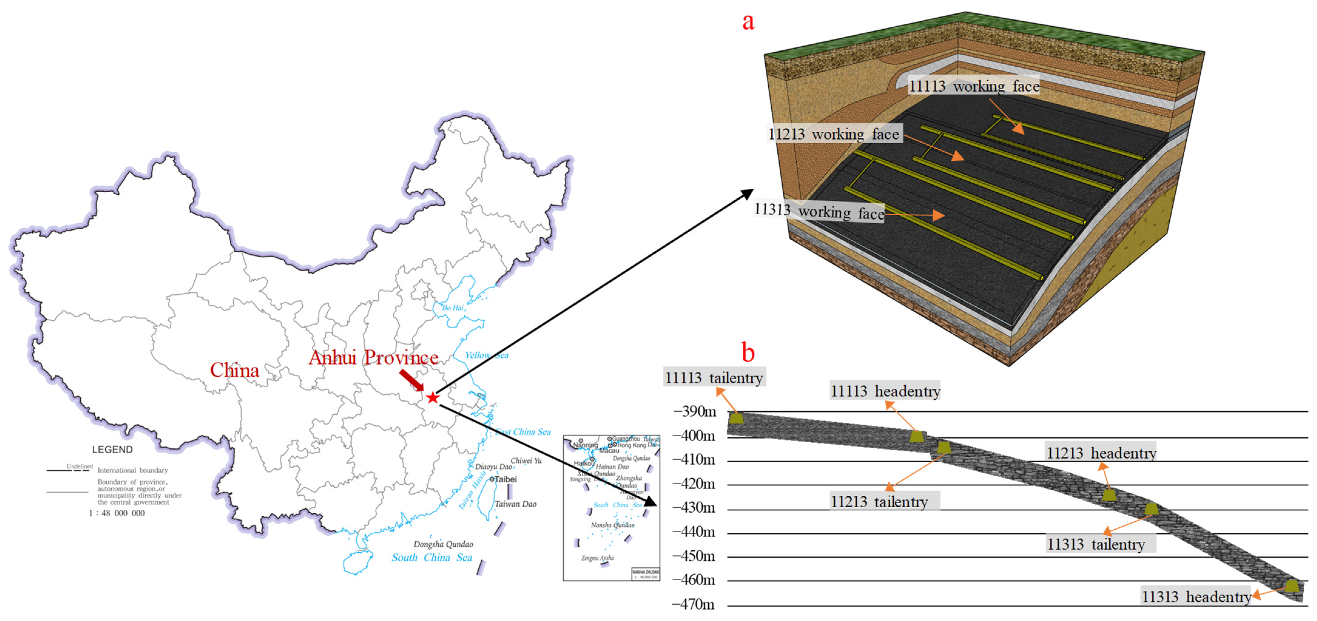
2. Case Study
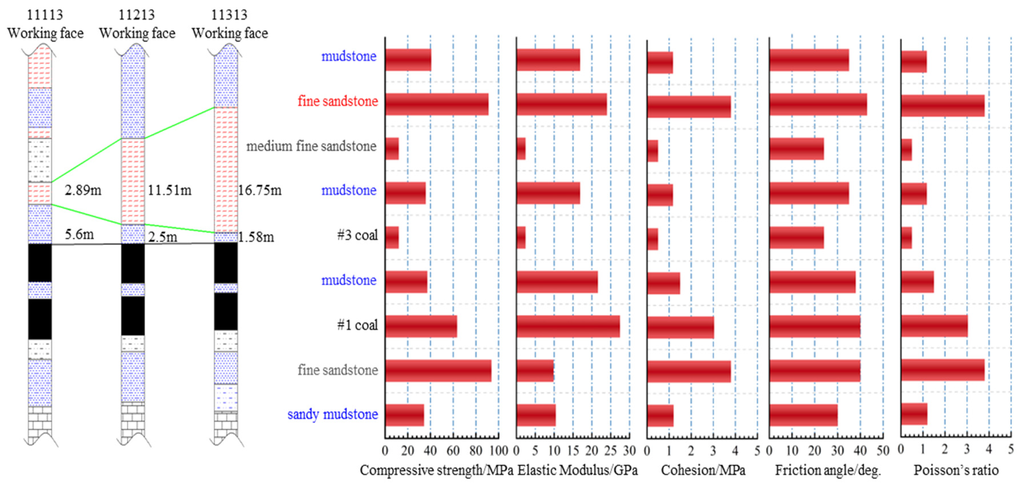
- Working face 11113, N > 5, belonged to class I roof condition. The thicknesses of overlying rock formations were small, and the roof rock contained fractures.
- Working face 11213, 2 < N < 5, belonged to class Ⅱ roof condition. There was an immediate roof of size 2.0~9.0 m between the main roof and the coal seam.
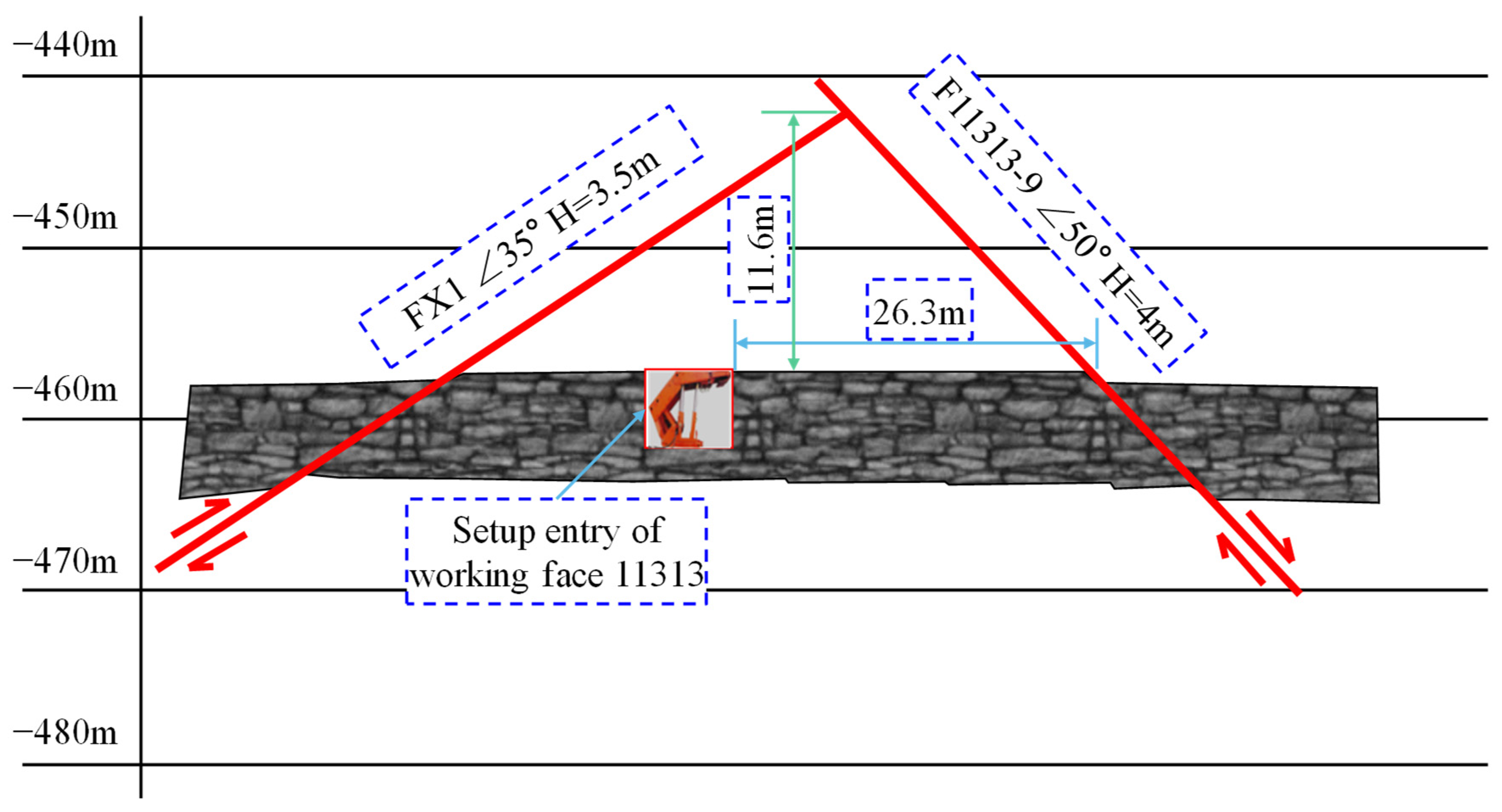
- Working face 11313, N < 2, belonged to class Ⅲ roof condition. The lithology of the main roof is medium-fine sandstone. A small amount of 1~2 m mudstone roof was contained between the main roof and the coal seam and almost no immediate roof was present.
3. Characteristics of Strata Behavior with Abnormal Roof
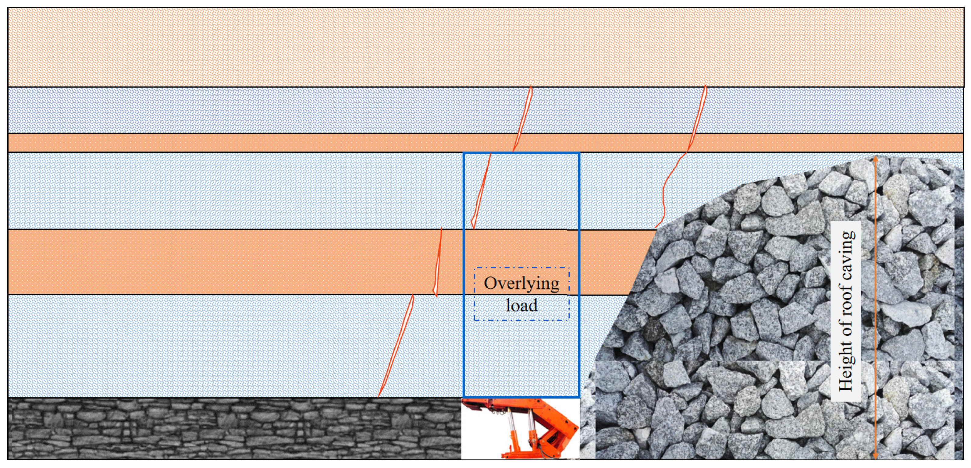
3.1. Caving Characteristics of Abnormal Roof
3.2. Weighting Characteristic of Abnormal Roof
3.2.1. Working Face 11113
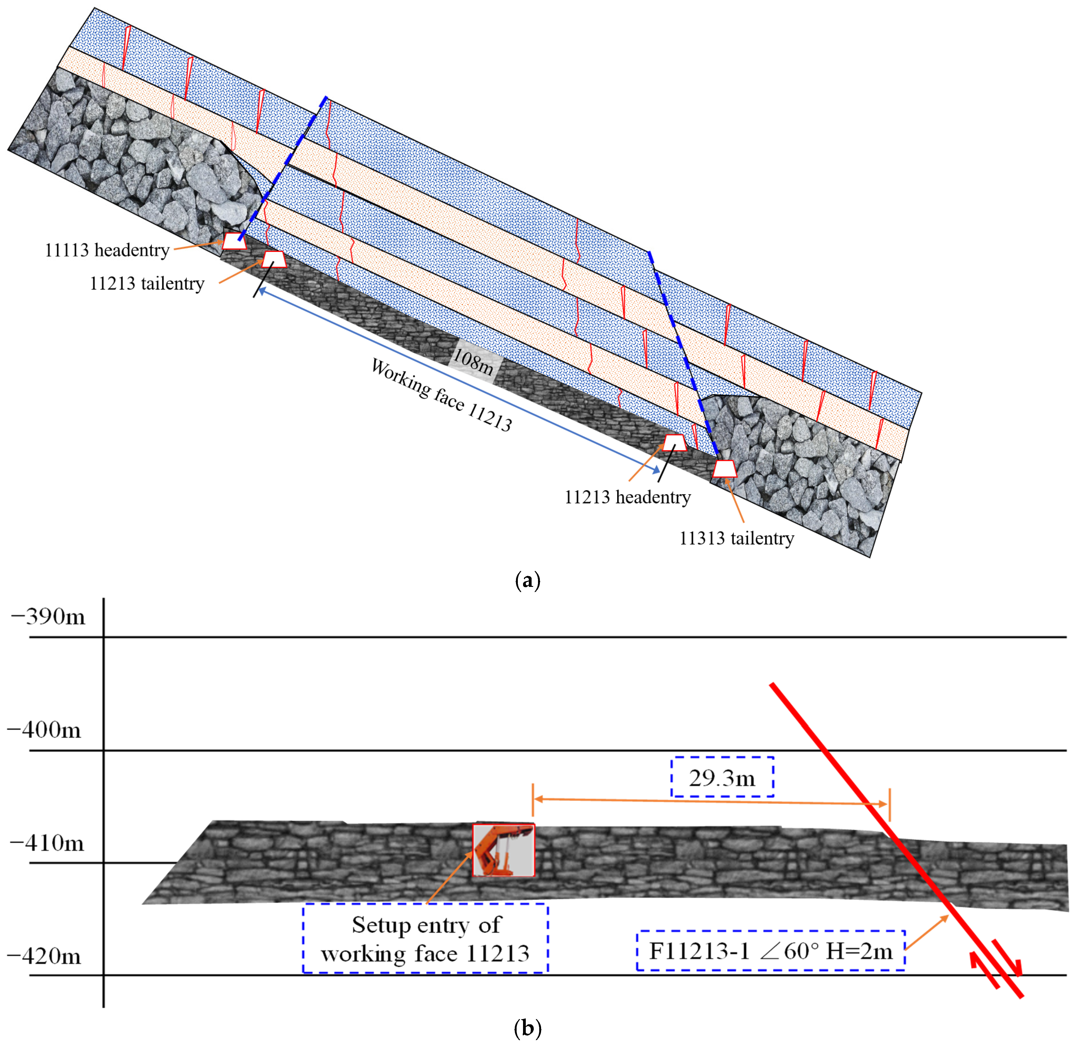
3.2.2. Working Face 11213
3.2.3. Working Face 11313
4. Numerical Simulation
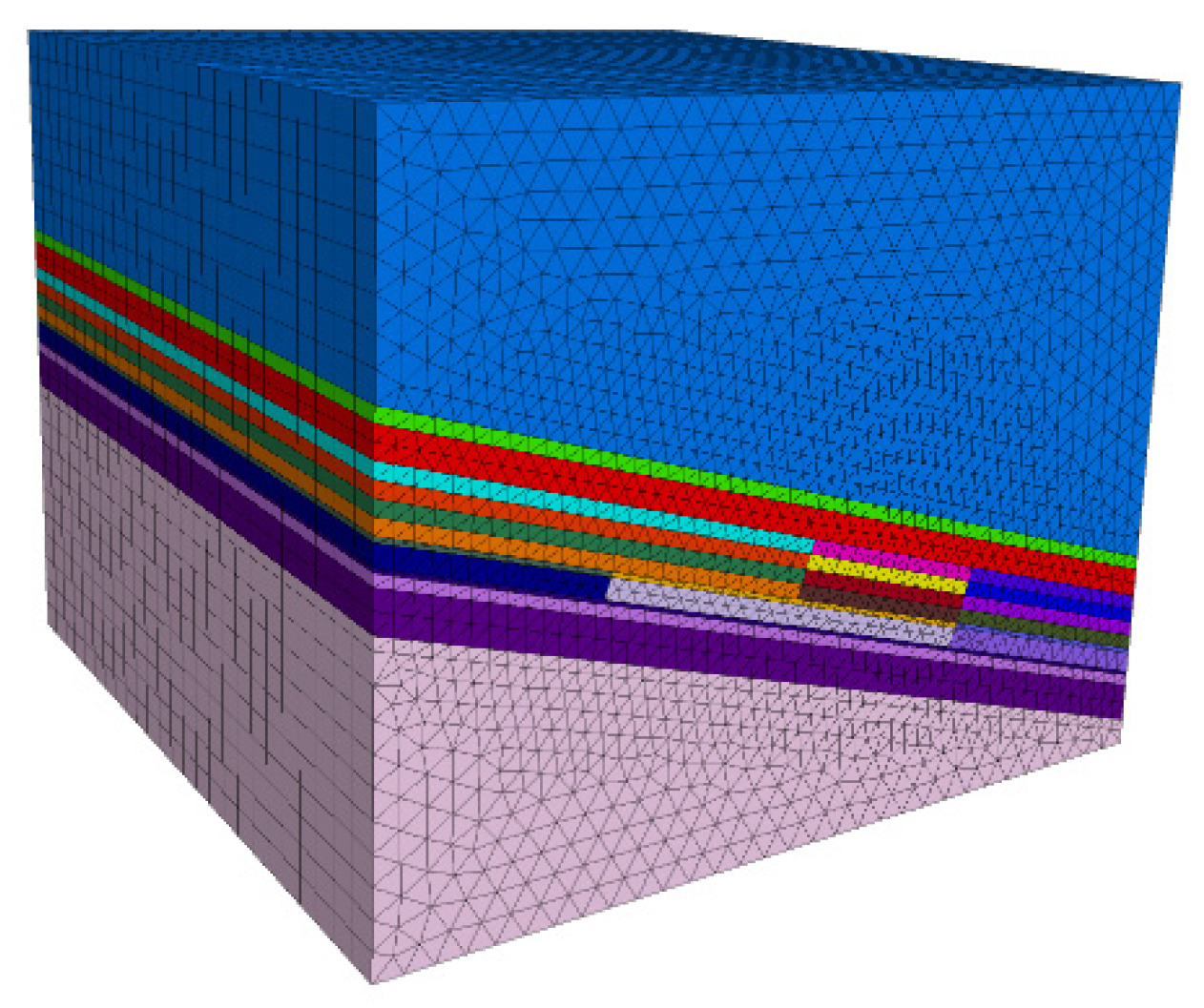
4.1. Model Establishment
4.2. Analysis of Results
5. Ground Pressure Control
5.1. Support Selection of Working Face
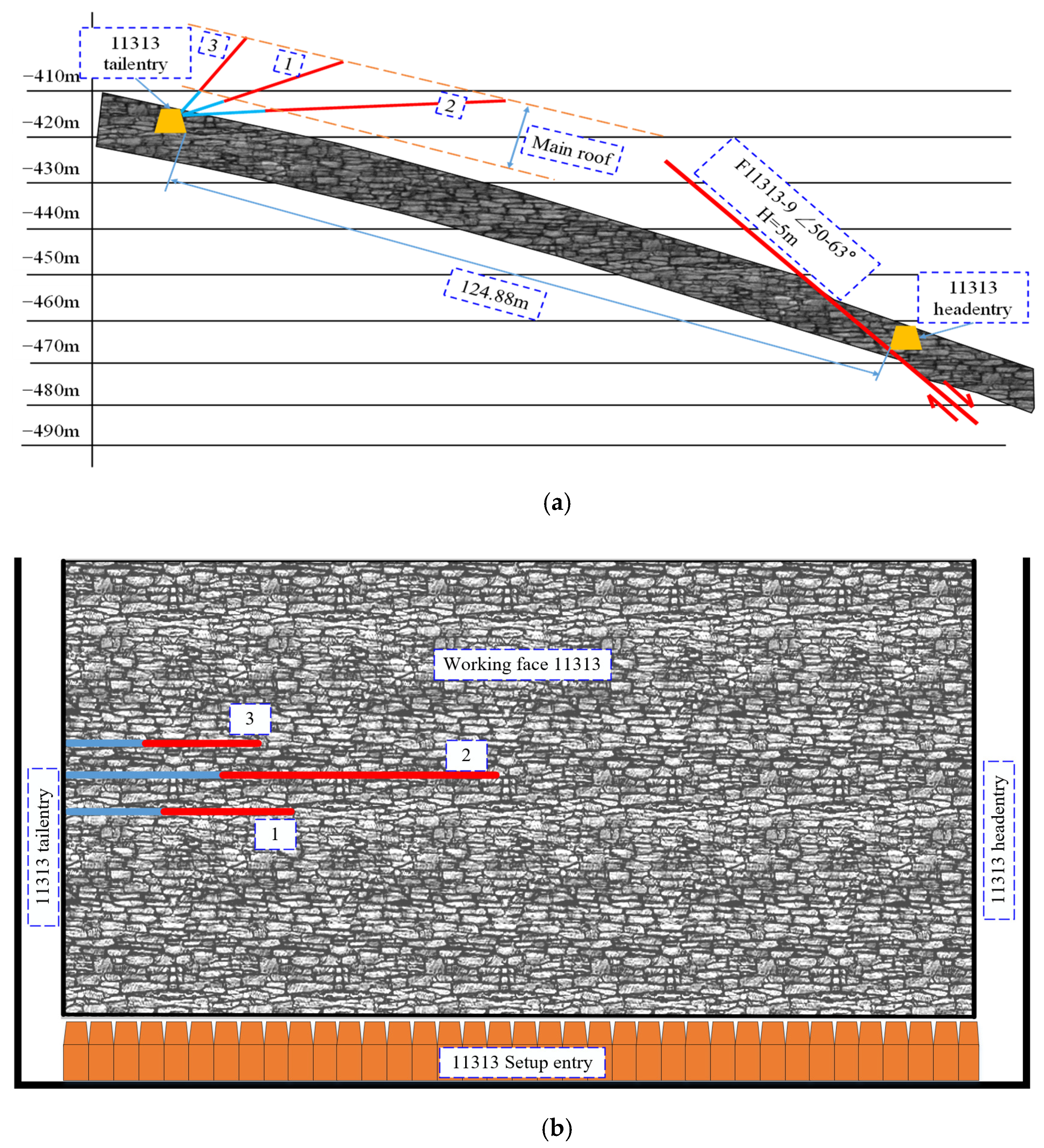
5.2. Scheme of Deep Hole Pre-Split Blasting
5.2.1. Initial Caving
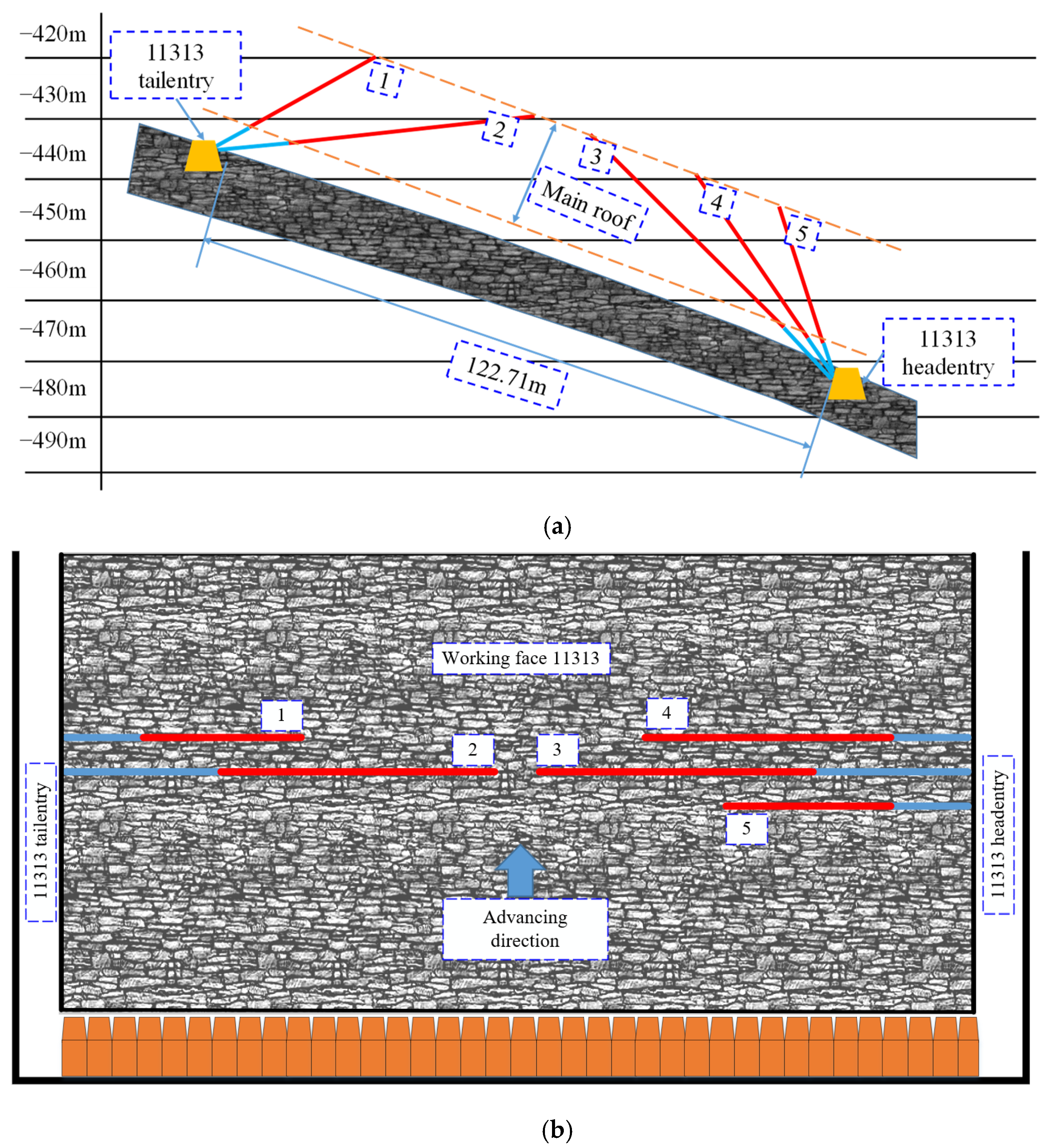
5.2.2. Periodic Weighting Caving
5.3. Roof Control Scheme in Fault Zone
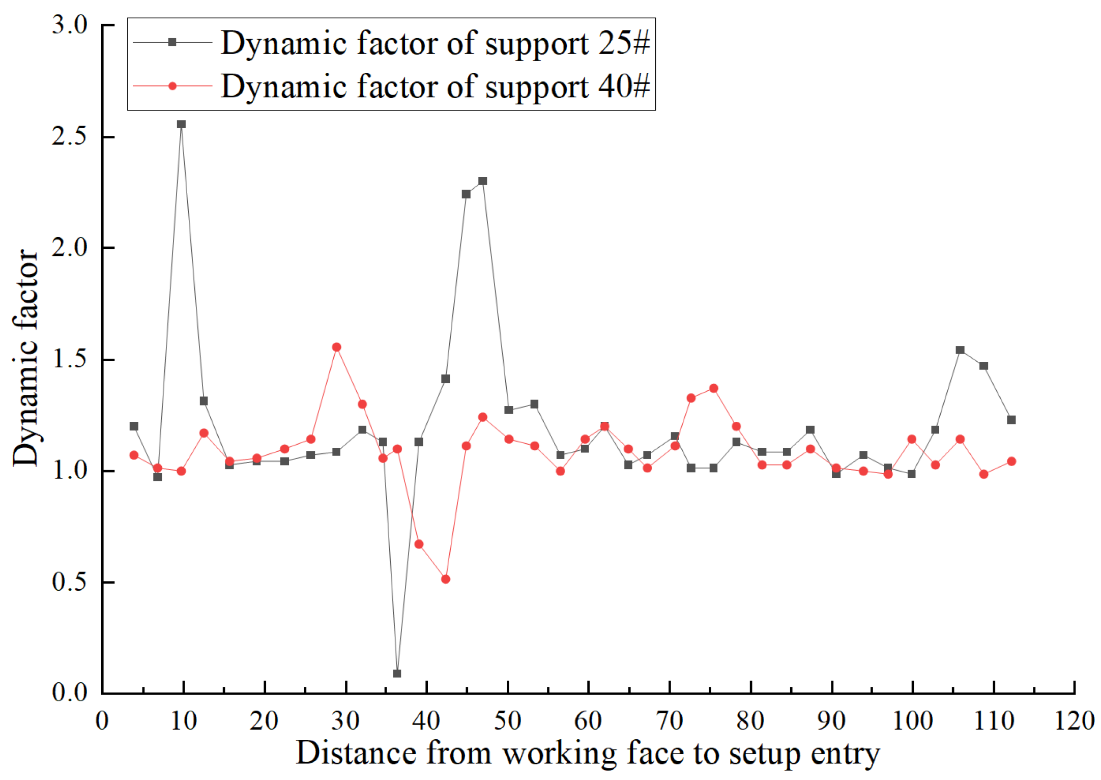
5.4. Field Measurement of Ground Pressure
6. Discussion
7. Conclusions
- (1)
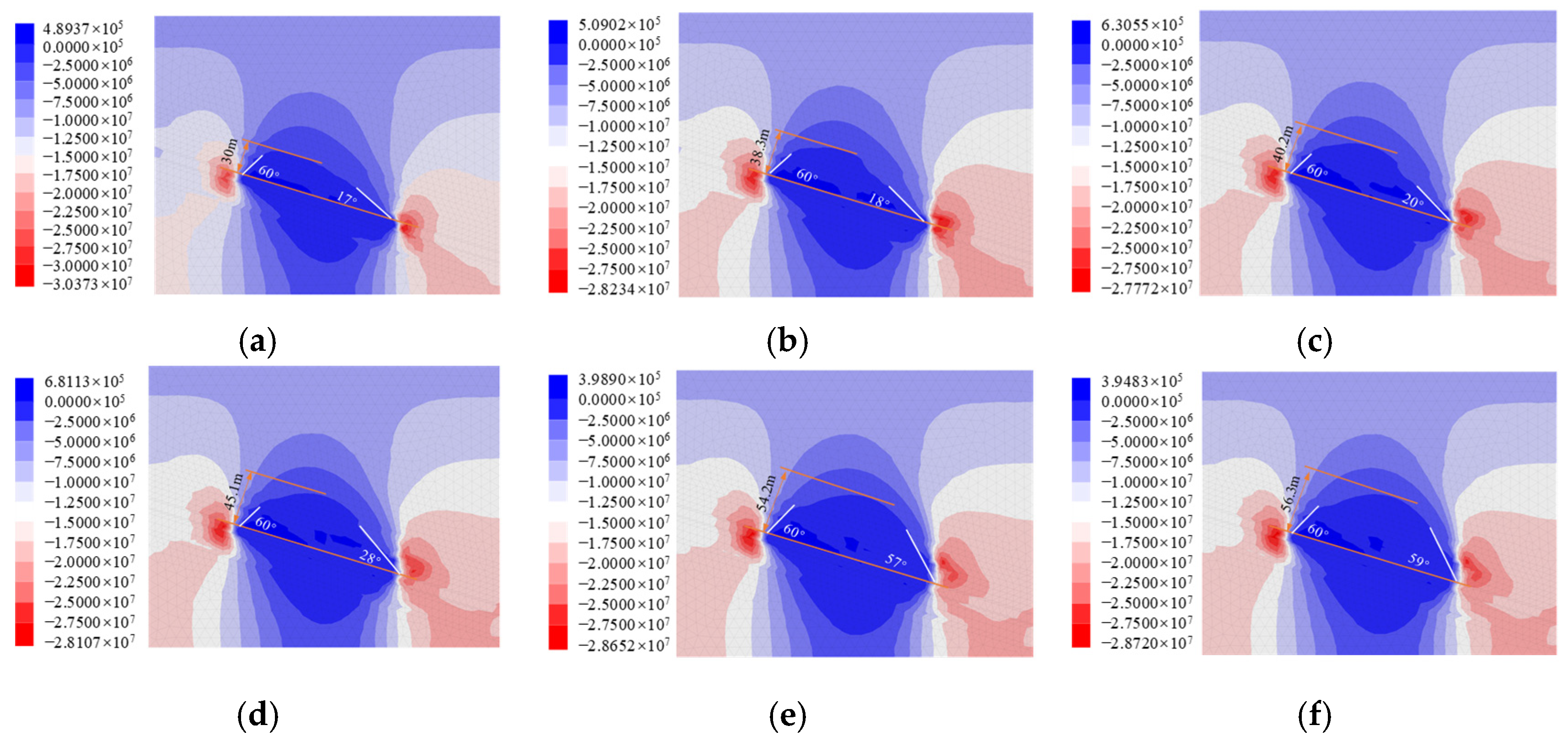
- As the deep hole pre-split blasting thickness of the main roof increases, the stress arch rotates to the blasting side, and the stress arch height increases with the blasting depth from spoon shape to oval shape. The stress arch height increased to 54.2 m, with an inclination angle of the stress arch on the side of the working face of 60°.
- (2)
- Herein, a two-deep hole pre-splitting blasting scheme to set up the entry section and long suspended roof section was proposed. This helped reduce the first weighting strength of working face 11313 below 34 Mpa and the roof suspension distance within 15 m, which effectively weakened the impact of severe ground pressure.
- (3)
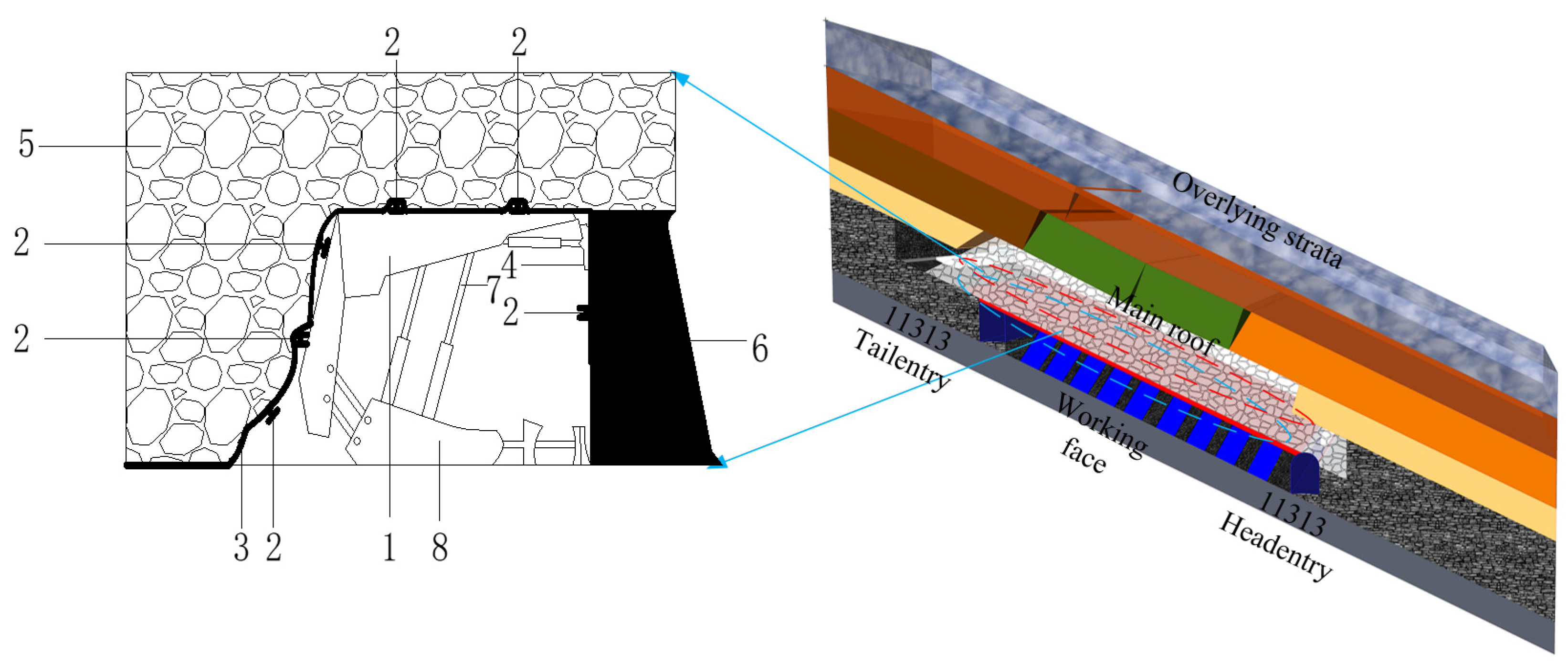
- The roof mesh laying and hanging method with advanced hanging mesh protection was proposed. This method effectively controlled roof fall and rib spalling.
Author Contributions
Funding
Data Availability Statement
Acknowledgments
Conflicts of Interest
References
- Zhu, S.; Jiang, Z.; Zhou, K.; Peng, G.; Yang, C. The characteristics of deformation and failure of coal seam floor due to mining in Xinmi coal field in China. Bull. Eng. Geol. Environ. 2014, 73, 1151–1163. [Google Scholar] [CrossRef]
- Wang, J. Development and prospect on fully mechanized mining in Chinese coal mines. Int. J. Coal Sci. Technol. 2014, 1, 253–260. [Google Scholar] [CrossRef] [Green Version]
- Zhang, C.; Tu, S.; Zhao, Y. Compaction characteristics of the caving zone in a longwall goaf: A review. Environ. Earth Sci. 2019, 78, 27–42. [Google Scholar] [CrossRef]
- Gao, R.; Kuang, T.; Zhang, Y.; Zhang, W.; Quan, C. Controlling mine pressure by subjecting high-level hard rock strata to ground fracturing. Int. Coal Sci. Technol. 2021, 8, 1336–1350. [Google Scholar] [CrossRef]
- Wang, J.; Yu, B.; Kang, H.; Wang, G.; Mao, D.; Liang, Y.; Jiang, P. Key technologies and equipment for a fully mechanized top-coal caving operation with a large mining height at ultra-thick coal seams. Int. Coal Sci. Technol. 2015, 2, 97–161. [Google Scholar] [CrossRef] [Green Version]
- Patyk, M.; Bodziony, P.; Krysa, Z. A Multiple Criteria Decision Making Method to Weight the Sustainability Criteria of System Selection for Surface Mining. Energies 2021, 14, 3066. [Google Scholar] [CrossRef]
- Tu, H.; Tu, S.; Yuan, Y.; Wang, F.; Bai, Q. Present situation of fully mechanized mining technology for steeply inclined coal seams in China. Arab. Geosci. 2015, 8, 4485–4494. [Google Scholar] [CrossRef]
- Bahrani, N.; Hadjigeorgiou, J. Influence of stope excavation on drift convergence and support behavior: Insights from 3D continuum and discontinuum models. Rock Mech. Rock Eng. 2018, 51, 2395–2413. [Google Scholar] [CrossRef]
- Li, G.; Ma, F.; Guo, J.; Zhao, H.; Liu, G. Study on deformation failure mechanism and support technology of deep soft rock roadway. Eng. Geol. 2020, 264, 105262. [Google Scholar] [CrossRef]
- Dychkovskyi, R.; Shavarskyi, I.; Saik, P.; Lozynskyi, V.; Falshtynskyi, V.; Cabana, E. Research into stress-strain state of the rock mass condition in the process of the operation of double-unit longwalls. Min. Miner. Depos. 2020, 14, 85–94. [Google Scholar] [CrossRef]
- Jia-Chen, W. Mechanism of the rib spalling and the controlling in the very soft coal seam. J. China Coal Soc. 2007, 32, 785–788. [Google Scholar]
- Vu, T.T. Solutions to prevent face spall and roof falling in fully mechanized longwall at underground mines, Vietnam. Min. Miner. Depos. 2022, 16, 127–134. [Google Scholar] [CrossRef]
- Babets, D.; Sdvyzhkova, O.; Shashenko, O.; Kravchenko, K.; Cabana, E.C. Implementation of probabilistic approach to rock mass strength estimation while excavating through fault zones. Min. Miner. Depos. 2019, 13, 72–83. [Google Scholar] [CrossRef] [Green Version]
- Li, T.; Mu, Z.; Liu, G.; Du, J.; Lu, H. Stress spatial evolution law and rockburst danger induced by coal mining in fault zone. Int. J. Min. Sci. Technol. 2016, 26, 409–415. [Google Scholar] [CrossRef]
- Li, Z.; Wang, C.; Shan, R.; Yuan, H.; Zhao, Y.; Wei, Y. Study on the influence of the fault dip angle on the stress evolution and slip risk of normal faults in mining. Bull. Eng. Geol. Environ. 2021, 80, 3537–3551. [Google Scholar] [CrossRef]
- Dai, J.; Jiang, J. Influence of mining sequence of hanging wall and foot wall on mining-induced stress of fault coal pillar. J. Min. Saf. Eng. 2016, 33, 35–41. [Google Scholar]
- Ju, J.; Xu, J. Structural characteristics of key strata and strata behaviour of a fully mechanized longwall face with 7.0 m height chocks. Int. Rock Mech. Min. Sci. 2013, 58, 46–54. [Google Scholar] [CrossRef]
- Fan, J.; Dou, L.; He, H.; Du, T.; Zhang, S.; Gui, B.; Sun, X. Directional hydraulic fracturing to control hard-roof rockburst in coal mines. Int. Min. Sci. Technol. 2012, 22, 177–181. [Google Scholar] [CrossRef]
- Dou, L.; Mu, Z.; Li, Z.; Cao, A.-Y.; Gong, S.-Y. Research progress of monitoring, forecasting, and prevention of rockburst in underground coal mining in China. Int. Coal Sci. Technol. 2014, 1, 278–288. [Google Scholar] [CrossRef] [Green Version]
- Cui, F.; Dong, S.; Lai, X.; Chen, J.; Cao, J.; Shan, P. Study on rule of overburden failure and rock burst hazard under repeated mining in fully mechanized top-coal caving face with hard roof. Energies 2019, 12, 4780. [Google Scholar] [CrossRef] [Green Version]
- Guo, W.; Wang, H.; Dong, G.; Li, L.; Huang, Y.-G. A case study of effective support working resistance and roof support technology in thick seam fully-mechanized face mining with hard roof conditions. Sustainability 2017, 9, 935. [Google Scholar] [CrossRef] [Green Version]
- He, J.; Dou, L.; Mu, Z.; Cao, A.-Y.; Gong, S.-Y. Numerical simulation study on hard-thick roof inducing rock burst in coal mine. J. Cent. South Univ. 2016, 23, 2314–2320. [Google Scholar] [CrossRef]
- Lu, A.; Dou, L.; Bai, J.; Chai, Y.; Zhou, K.; Kan, J.; Cao, J.; Song, S. Mechanism of Hard-Roof Rock Burst Control by the Deep-Hole Blasting, Numerical Study Based on Particle Flow. Shock. Vib. 2021, 2021, 9527956. [Google Scholar] [CrossRef]
- Sun, Z.; Zhang, D.; Fang, Q.; Dui, G.; Tai, Q.; Sun, F. Analysis of the interaction between tunnel support and surrounding rock considering pre-reinforcement. Tunn. Undergr. Space Technol. 2021, 115, 104074. [Google Scholar] [CrossRef]
- He, H.; Dou, L.; Fan, J.; Du, T.; Sun, X. Deep-hole directional fracturing of thick hard roof for rockburst prevention. Tunn. Undergr. Space Technol. 2012, 32, 34–43. [Google Scholar] [CrossRef]
- Wang, F.; Tu, S.; Yuan, Y.; Feng, Y.; Chen, F.; Tu, H. Deep-hole pre-split blasting mechanism and its application for controlled roof caving in shallow depth seams. Int. Rock Mech. Min. Sci. 2013, 64, 112–121. [Google Scholar] [CrossRef]
- Huang, B.; Liu, J.; Quan, Z. The reasonable breaking location of overhanging hard roof for directional hydraulic fracturing to control strong strata behaviors of gob-side entry. Int. Rock Mech. Min. Sci. 2018, 103, 1–11. [Google Scholar] [CrossRef]
- Yang, J.; Liu, C.; Yu, B. Application of confined blasting in water-filled deep holes to control strong rock pressure in hard rock mines. Energies 2017, 10, 1874. [Google Scholar] [CrossRef] [Green Version]
- Zhao, Y.X.; Wang, T.; Jiang, Y.D.; Pan, L.; Zhang, K.X. Application of Hoek-Brown criterion in numerical simulation of ground pressure features in multi-seam longwall mining. J. China Coal Soc. 2013, 38, 970–976. [Google Scholar]
- Asheghi, R.; Shahri, A.A.; Khorsand, Z.M. Prediction of uniaxial compressive strength of different quarried rocks using metaheuristic algorithm. Arab. J. Sci. Eng. 2019, 44, 8645–8659. [Google Scholar] [CrossRef]
- Zhao, Y.; Yang, T.; Zhang, P.; Zhou, J.; Yu, Q.; Deng, W. The analysis of rock damage process based on the microseismic monitoring and numerical simulations. Tunn. Undergr. Space Technol. 2017, 69, 1–17. [Google Scholar] [CrossRef]
- Hoek, E.; Kaiser, P.K.; Bawden, W.F. Support of Underground Excavations in Hard Rock; Balkema: Rotterdarn, The Netherlands, 1995. [Google Scholar]
- Cheng, S.; Ma, Z.; Gong, P.; Li, K.; Li, N.; Wang, T. Controlling the deformation of a small coal pillar retaining roadway by non-penetrating directional pre-splitting blasting with a deep hole, A case study in Wangzhuang coal mine. Energies 2020, 13, 3084. [Google Scholar] [CrossRef]
- Wang, X.; Zhu, W.; Xu, J.; Han, H.; Fu, X. Mechanism of overlying strata structure instability during mining below unconsolidated confined aquifer and disaster prevention. Appl. Sci. 2021, 11, 1778. [Google Scholar] [CrossRef]


| Working Face | Roof Category | First Weighting Interval (L/m) | Periodic Weighting Interval (m) | |||
|---|---|---|---|---|---|---|
| Working face 11113 | Ⅰ | 74.0 | 33.6 | / | 29.6 | 12.1 |
| Working face 11213 | Ⅱ | 309.2 | 417.4 | 95.2 | 38.0 | 15.5 |
| Working face 11313 | Ⅲ | 449.6 | 638.7 | 108.7 | 44.7 | 18.2 |
| Rock Mass Characteristics | Damage Factor D |
|---|---|
| The blasting effect is poor, and the hard rock roadway is partially damaged | D = 0.8 |
| Small and medium-scale blasting caused blasting of rock mass | D = 0.7 Good blasting effect D = 1.0 Poor blasting effect |
| Mass production blasting caused significant disturbances | D = 1.0 Good blasting effect D = 0.7 Poor blasting effect |
| Lithology | Bulk Modulus/Gpa | Shear Modulus/GPa | Cohesion/MPa | Internal Friction Angle/° |
|---|---|---|---|---|
| Medium-fine sandstone | 3.6 | 3.9 | 1.5 | 20 |
| Roadway Name | Blast Hole Serial Number | Blast Hole Depth/m | Dip Angle/° | Blast Hole Diameter/mm | Charge Length/m | Blocking Length/m |
|---|---|---|---|---|---|---|
| 11313 tailentry | 1# | 19 | 34 | 94 | 14 | 5 |
| 2# | 55 | 3 | 94 | 45 | 10 | |
| 3# | 17 | 70 | 94 | 16 | 4 |
| Roadway Name | Blast Hole Serial Number | Blast Hole Depth/m | Dip Angle/° | Blast Hole Diameter/mm | Charge Length/m | Blocking Length/m |
|---|---|---|---|---|---|---|
| 11313 tailentry | 1# | 27 | 34 | 94 | 21 | 6 |
| 2# | 65 | 9 | 94 | 55 | 10 | |
| 11313 headentry | 3# | 65 | 45 | 94 | 55 | 10 |
| 4# | 37 | 65 | 94 | 30 | 7 | |
| 5# | 30 | 85 | 94 | 24 | 6 |
Publisher’s Note: MDPI stays neutral with regard to jurisdictional claims in published maps and institutional affiliations. |
© 2022 by the authors. Licensee MDPI, Basel, Switzerland. This article is an open access article distributed under the terms and conditions of the Creative Commons Attribution (CC BY) license (https://creativecommons.org/licenses/by/4.0/).
Share and Cite
Fu, Q.; Yang, K.; He, X.; Wei, Z.; Yang, Q. Characteristics of Strata Behavior and Differentiated Control of Fully Mechanized Mining Working Face with Abnormal Roof. Sustainability 2022, 14, 13354. https://doi.org/10.3390/su142013354
Fu Q, Yang K, He X, Wei Z, Yang Q. Characteristics of Strata Behavior and Differentiated Control of Fully Mechanized Mining Working Face with Abnormal Roof. Sustainability. 2022; 14(20):13354. https://doi.org/10.3390/su142013354
Chicago/Turabian StyleFu, Qiang, Ke Yang, Xiang He, Zhen Wei, and Qinggan Yang. 2022. "Characteristics of Strata Behavior and Differentiated Control of Fully Mechanized Mining Working Face with Abnormal Roof" Sustainability 14, no. 20: 13354. https://doi.org/10.3390/su142013354