1. Introduction
The plastics injection industry is an extremely challenging sector as it dedicates its production to other types of extremely competitive industries, such as the automotive segment and the sector of household items and packaging, among many others. Therefore, the plastics industry constantly seeks to increase its productivity, as innovation is a determining factor in the survival of this sector [
1,
2], which can be viewed from different angles. The sector is constantly looking to broaden its influence through the launch of new products where the weight factor is extremely important, and plastics can be a solution due to their characteristically low density. This factor assumes an even greater magnitude when the manufactured parts take on even greater proportions, where the replacement of materials and the development of new technologies can allow the industry to reach market segments that are still little-explored [
3]. Given the cost structures normally linked to this industry, it is easy to see that there are two fundamental factors which can affect the competitiveness of the process: the moulds’ durability and cycle time management, with particular emphasis on the cooling/solidification time of the injected components. The durability of moulds has been a permanent target for many studies, especially when abrasive reinforcements are injected together with plastics [
4,
5]. On the other hand, cycle time has also been studied in terms of technology [
6,
7] and management [
1]. However, the plastic injection process is not confined to the injection operation itself, especially in more complex parts commonly supplied to the automotive industry, requiring its extraction from the mould and interconnected operations, such as the inspection and assembly of other components. In this perspective, the help of automation and robotics has been proven to be fundamental [
8].
Depending on the operations’ complexity and the desired flexibility, there are cases where automation is considered the best solution, especially for large series of the same type of product, whereas robotics is employed when greater flexibility is required. The literature is vast in examples in which either one solution or the other, or a combination of both, have led to excellent results in terms of increased productivity, improved levels of repeatability and quality, and even a drastic reduction of repetitive tasks that usually cause health problems for operators [
9,
10]. Seeber et al. [
11] studied the physical interactions between the different resources existing in a workstation, trying to establish methodologies that help Process Engineers in the design of these workstations. Silva et al. [
8] developed an automatic solution for inserting previously shaped wires into a mould, where plastic over-injection was performed on the ends of these wires. In this case, the authors opted for automation without robotics, as the setup time needed to change production from one reference to another was small, and changes in the product to be manufactured were infrequent. Considering these factors, the authors argued that a solution based on automation was significantly more economical and perfectly sufficient to make the process much more productive and competitive. Taking into account the previous process of this same product, i.e., the bent wire, Magalhães et al. [
12] developed an innovative system based solely on automation in order to guide, inspect, and prepare the product for the next phase. In this case, the developed system could be manufactured at a significantly lower cost than an industrial robot. Furthermore, the system occupied less space, allowed for a faster cycle time than a robot, could be perfectly adjustable to the cycle time of the equipment responsible for forming the wire, and sorted the bent wires, placing them in the supply position for the next process, developed in [
8]. Regarding the savings achieved by this solution, the return-on-investment calculated for the new equipment was less than 9 months, which clearly shows the advantages provided by the carried-out study. Araújo et al. [
13] developed a new subproduct-transport concept in the manufacturing process of the cushions and suspension mats used in car seat structures. The developed system, based solely on traditional automation, allowed for the reduction of two previously necessary jobs, guaranteeing higher quality assurance and greater productivity, by achieving an efficiency gain of about 40%. Quality assurance was also the main motivation for the work carried out by Costa et al. [
14] based on a transmission set usually integrated in the windshield wiper system of automobiles. The initial system allowed for the possibility of a wrong system assembly, which was only semi-automatic, due to the incorporation of human labour. For this reason, the level of defectively assemblies was high enough to cause concern about the process’ sustainability. Thus, a new fully automatic equipment was designed from scratch, based only on conventional automation, which allowed for the solving of quality problems in a totally effective way. The return-on-investment calculated was around 2 years, which is perfectly compatible with the investments normally made in the automotive components industry. The Bowden cables manufacturing process has also been the subject of several productivity improvements based on the use of conventional automation. Moreira et al. [
15] and Martins et al. [
16] developed systems that allowed for the aggregation of different processes in a single piece of equipment, thus reducing the management of semi-products between different stages of the Bowden cables’ manufacturing process, with perfectly quantified benefits. Several other studies [
17,
18,
19] have been developed defending that, in certain situations, the concept to solve certain problems can only go through solutions based on conventional automation to the detriment of robotics, making the investment more easily amortized and allowing for some flexibility [
20,
21].
Contrary to the previously reported situations, many other investigations have been carried out in the field of robotics, often in close-collaboration with conventional automation. The use of robotics in manufacturing cells must be scrupulously studied, with a view on reducing the displacement time of robots and the energy consumed as much as possible, as described by Gadaleta et al. [
22] and Gultekin et al. [
23]. Robotics can be affected by inaccuracies of the robotic arm in relation to the jig where the different parts to be joined or assembled are placed. Aware of this possibility, Millington et al. [
24] developed a system for real-time positional correction, which, despite its simplicity, proved to meet the requirements initially established in terms of the accuracy of the robotic arm related to the jig, being supported by complex real-time mathematical calculations. Beyond the positioning of the parts by the robotic arm into the jig, robotics presents other challenges, namely possible collisions of the robot with jigs or even with the parts to be worked on; as such Mutti et al. [
25] developed their own algorithms to avoid this type of collision. Another challenge normally related to the application of robotic systems was also explored by Honarpardaz et al. [
26], namely the design of grippers necessary for handling parts or tools. This study aimed to simplify the design approach of these grippers, taking into account whether they perform only one operation, or if they need to perform multiple ones. As in most solutions based only on conventional automation, solutions based on robotics allow for the real-time control of industrial operations, which leads to a greater interaction between the different production cells, optimizing logistical operations and providing information on the real-time workflow [
27]. Séguin et al [
28] carried out a study to minimize the number of robots added to a given complex process, minimizing investment and avoiding collisions, without the cycle time being severely impaired. Chernweno and Torn [
29] developed a framework capable of decomposing the different tasks performed for a given manual process, with the objective on the study and successful implementation of a robotic system capable of replacing all operations performed manually. In order to validate the framework, a case study was developed that worked as a ‘proof-of-concept’. In addition to all the frameworks and models developed around robotics and automation, some case studies have also been presented referring to specific applications, demonstrating with real cases the advantages offered by the implementation of these systems. Matenga et al. [
30] successfully used robotics for the rewinding of the stators of electric motors, a task that is traditionally performed manually, given the complexity and diversity of the dimensions of these stators. This solution allowed for the rewinding task to be performed six times faster, with the advantage of allowing the collection of data that can be made accessible by the manufacturer and the customer. Silva et al. [
31] developed a robotic system for the inspection and packaging of suspension mats and cushions used to support foam blocks in car seat structures. Through artificial and robotic vision, each manufactured product is handled by a gripper specially designed for this purpose, which is located at the end of the line, promoting the phased inspection of each area most prone to manufacturing defects and then sorting these products inside a large box, where six product stacks are produced. The solution essentially aimed to increase the reliability in the analysis of the manufactured products and to reduce the manual labour associated with the process, with a view on avoiding repetitive work and generating occupational diseases.
Nevertheless, robotization is also no longer seen as an automation free from human work around it, instead starting to consider the integration of manual labour with the robotization of some tasks. Ruiz et al. [
32] called this trend hybridization; however, it is necessary to ensure the safety of employees who need to work within the volumetry defined for each robot, or for a set of robots, when that is the case. Johansen et al. [
33] defended the use of collaborative robots when production is based on a high diversity of products produced in relatively low quantities, due to a high degree of customization. A similar situation has been presented by Andronas et al. [
34]. Notwithstanding, there has still been a relatively low rate of application of this type of robots, with safety reasons being those that are most often cited as the cause for this reduced use [
35]. This problem is currently the subject of several studies and publications, thus revealing its importance [
36,
37,
38,
39]. In spite of this, there are already studies on the implementation of collaborative robotic systems in SMEs (small and medium enterprises), hence demonstrating that their adoption may be slow, but will certainly reach higher proportions in the relatively near future [
40]. However, the successive evolution of robots becomes worrying in industrial terms, as companies tend to discard first-generation robots in favour of more modern and agile ones with greater programming capacity and connection to peripheral systems. This constitutes an environmental problem that urgently needs to be resolved [
41]. Fortunately, although still in a tenuous way, studies are beginning to arise which aim to adapt first-generation robots to tasks previously performed only through conventional automation or through manual labour, and for which these robots have sufficient requirements, thus allowing their reuse, as an alternative to its complete disposal [
42].
This work aims to describe the framework developed in order to implement robotic solutions in the assembly of components. To make a ‘proof-of-concept’, the work also describes a case study in which the concept is successfully applied. This concept has been developed around a case study based on an injected plastic component used in automobiles, which in some components need to be assembled later, an operation previously performed manually. With the point to increase the precision and repeatability of the process, as well as improving the competitiveness of the product, a robot from one of the first generations was recovered, which was reprogrammed and adapted to the process. Furthermore, conditions were created in terms of peripheral components so that it could carry out the desired operations with the intended success. Thus, this work presents as its main novelty the development a solution able to improve the productivity by reusing previous devices already out-of-service, but good enough to help in improving the performance of manufacturing processes. The developed concept introduces some novel interesting mechanical solutions, which can be taken as examples regarding other needs in the same activity sector, or even in other kind of industries, helping by this way in overcoming difficult problems with simple and cheap solutions.
2. Materials and Methods
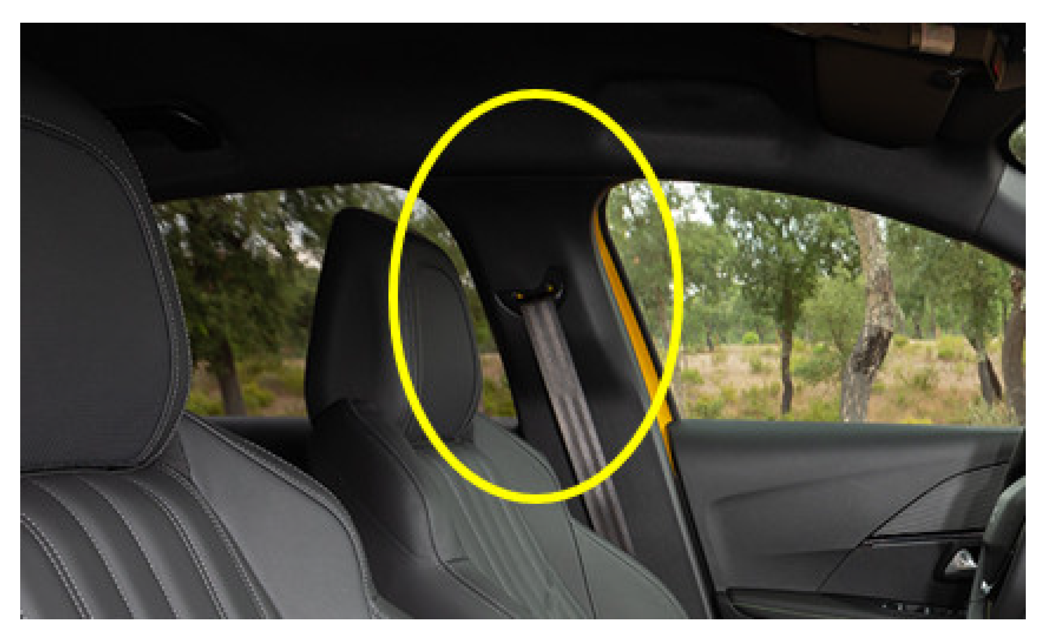
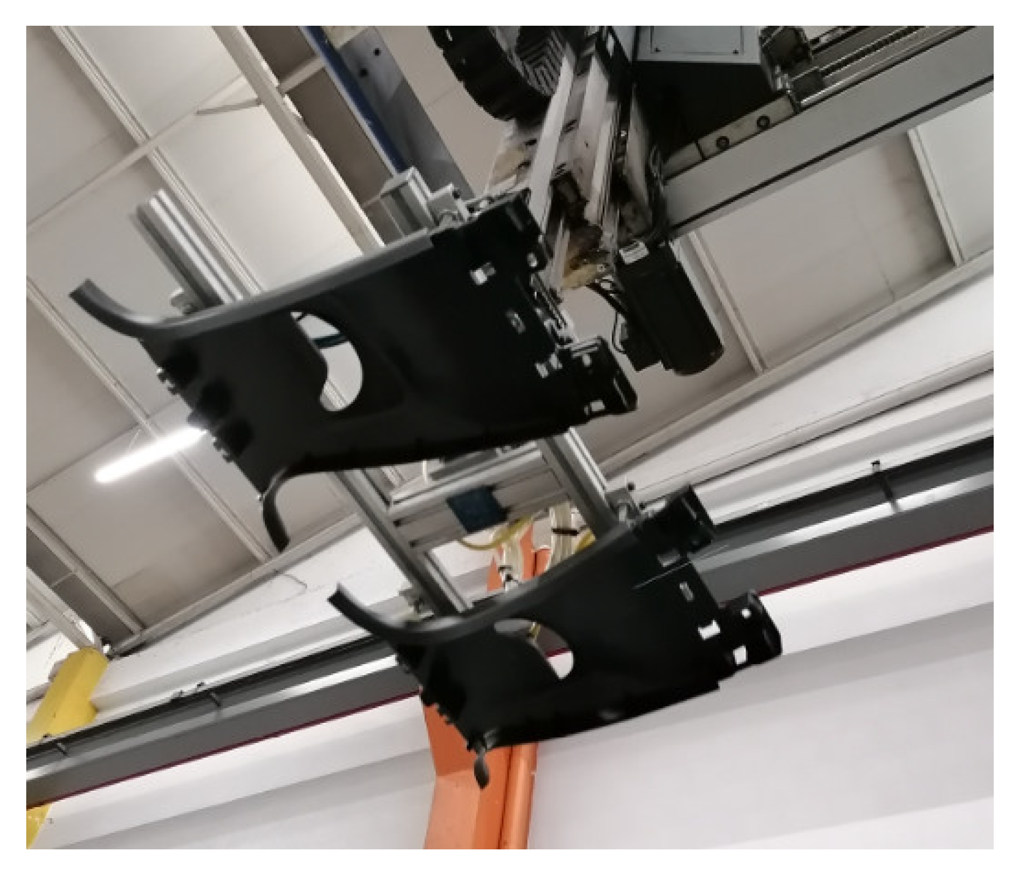
The main target of this work was the manufacturing and assembly process of components in plastics parts for the automotive sector obtained by injection moulding, namely the insertion of clips on finished injection moulded parts. The specific target to develop the concept was the production line of the mould MO.9163, which is responsible for producing the parts of the upper B-pillar of a well-known automotive vehicle, as shown in
Figure 1.
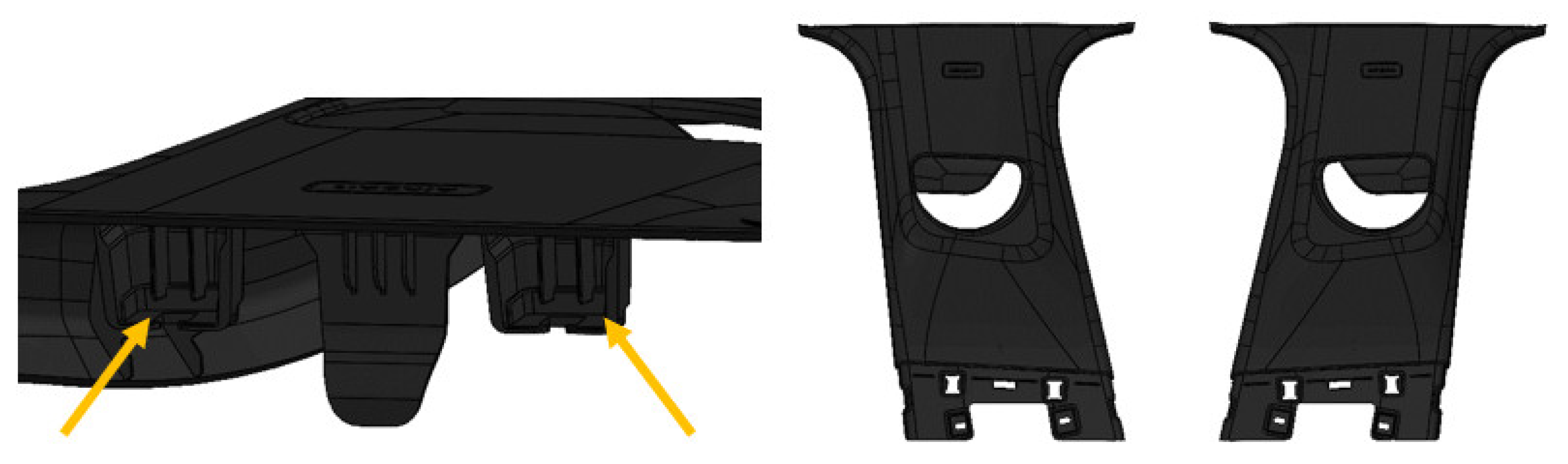
The targeted part is manufactured in Polypropylene at high pressure in the mould and removed by mechanical extraction. The part has two versions that differ only in the indication or not of the air bag. The mould used to produce these two versions is the same; however, when there is a change of version, it is necessary for the SMED’s (single-minute exchange of die) team to change the mould insert, i.e., the place that engraves ‘air bag’ on the part. These parts fit into the car body through two clips that are inserted by operators during the production process. The area where the clips are housed is called the clip holder, and can be seen in
Figure 2 (left). Since the component under study exists on both sides of the car (right B-pillar and left B-pillar), two parts have to be produced in a single injection, one for each side, as shown in
Figure 2 (right), with the clips being at the bottoms of the parts.
In the plastic injection process, the existence of channels through which the injection of the plastic into the mould is performed is usual; however, in this case, the plastic is injected directly into the mould cavity of the part, excluding the need to remove the gypsum from the parts, which usually leaves the mould still attached to the part.
The injection machine is responsible for the injection process of the plastic into the mould and controls all parameters (pressure, temperature, and time, among others) necessary to ensure the quality of the parts’ injection. If any defect occurs in the injection process of the parts, the machine immediately gives the order to reject the parts through the use of sensors.
2.1. Analysis of the Previous Concept
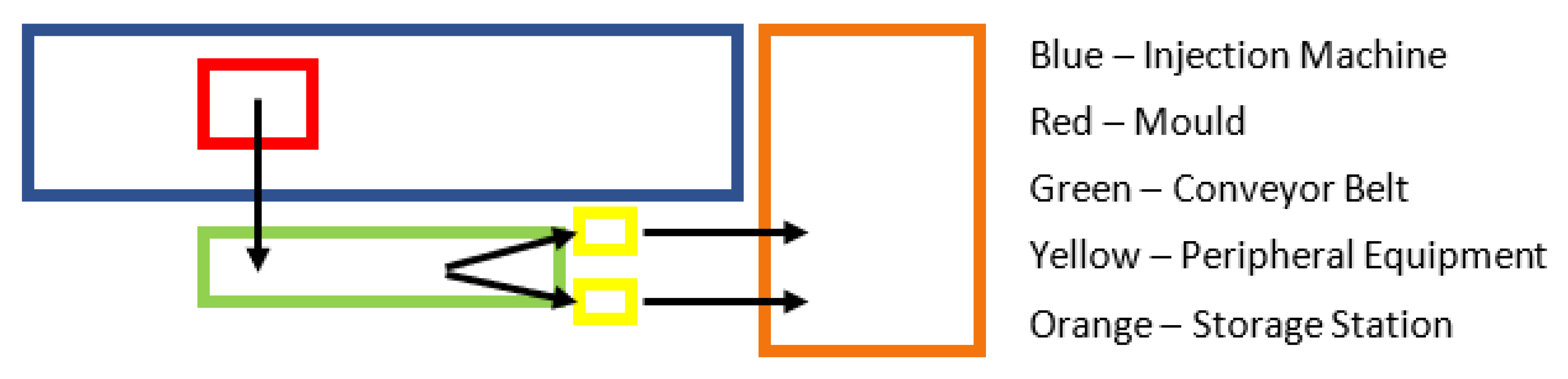
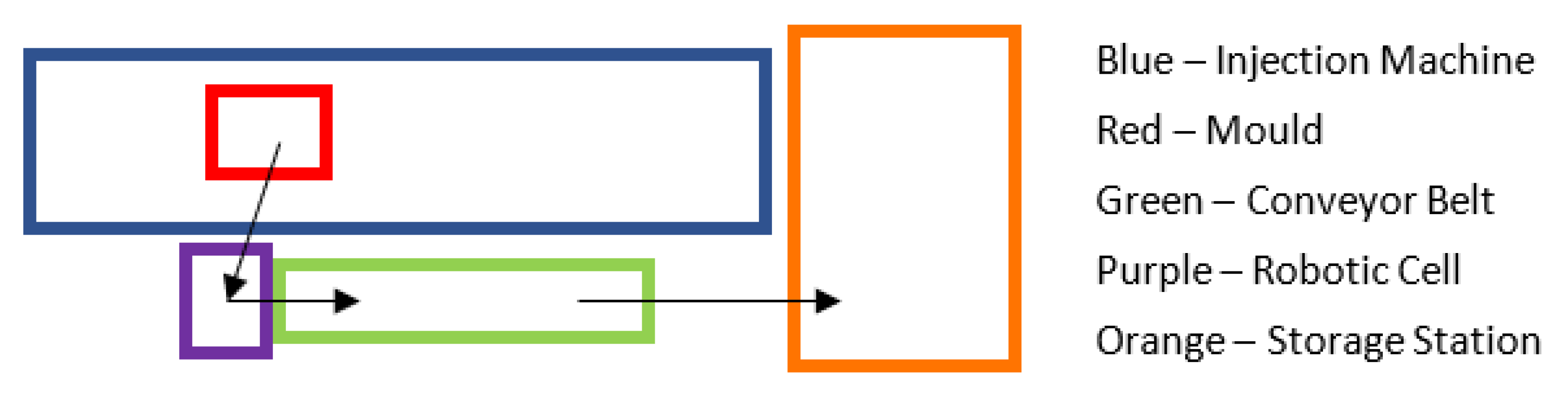
Prior to this project, the production line consisted of an injection machine, a conveyor belt where the parts were deposited after injection, two operators, and two peripheral equipment whose function was to perform the insertions of the clips and validate the necessary tasks.
Figure 3 provides an outline of the current workplace layout and the flow of parts from the mould to the initial storage station, which are then stored at the dispatch station.
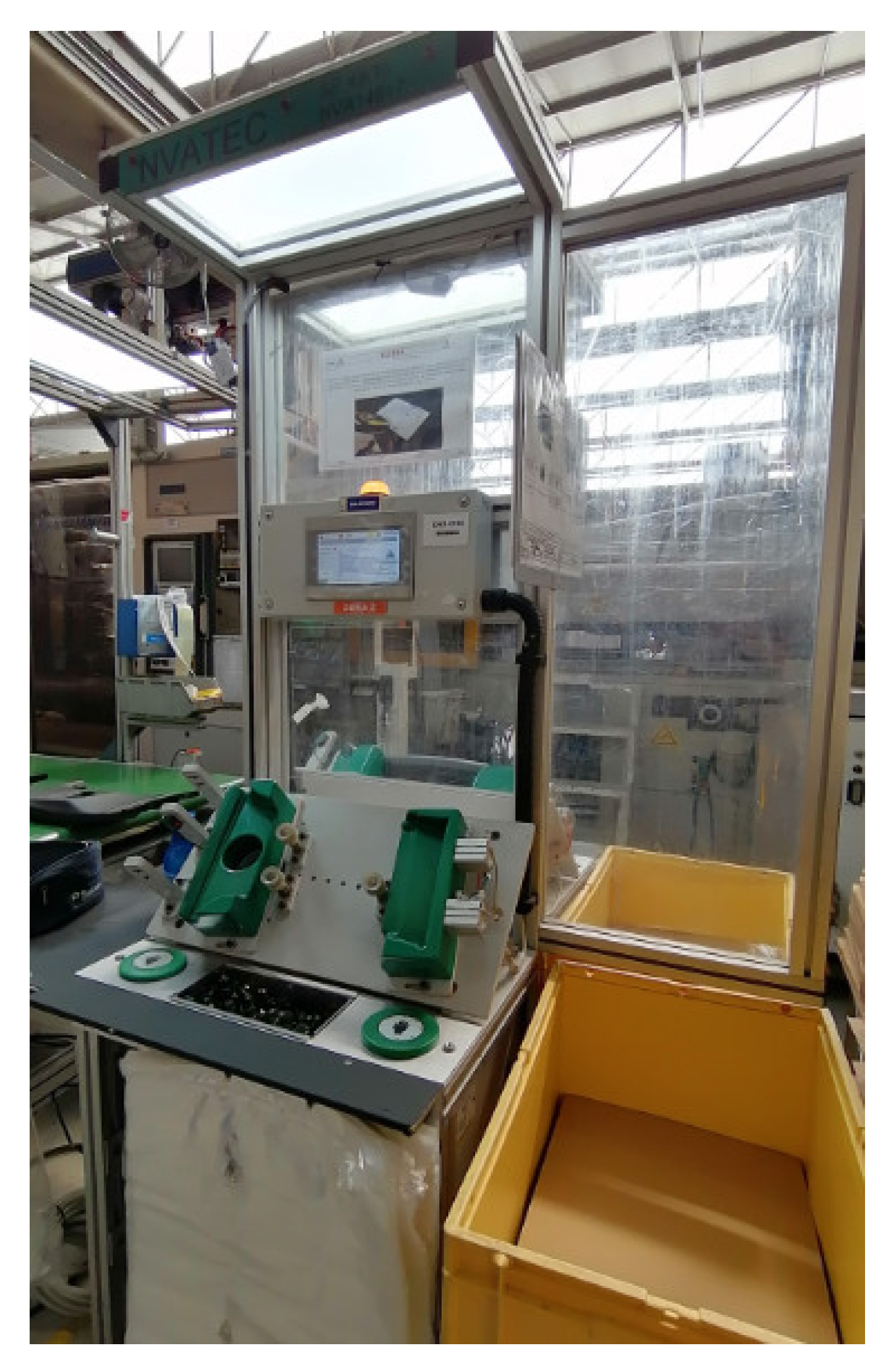
Currently, the control of the parts’ quality is performed by the peripheral equipment. When the part reaches the end of the conveyor belt, it is taken by the operators and placed in the peripheral equipment (
Figure 4).
Below, it is possible to see which parameters are controlled by the equipment, as well as its verification methods:
Checking the correct insertion of the springs—Sensor;
Checking for ‘incompletes’—Sensor;
Version of the part—Vision system;
Checking for appearance defects—Operator.
If the defined parameters are met, another very important task is performed in the equipment. The parts are pierced two times in order to verify afterwards if they have really passed through the equipment and if they have been properly validated, respectively.
The passing peak may vary from one equipment to another. Considering that this peak has to happen at the moment when the part is dropped in the equipment, it can be of static or dynamic in nature. It is called static when it is embedded in some surface of the equipment nests, which is in contact with the technical area of the part, and dynamic when it is not. On the other hand, the validation peak, usually designated the OK peak, must be dynamic, which only happens if all of the conditions for the part validation are met. This peak is performed by a pneumatic actuator, which leaves a slight mark on the part in order to show that it has passed the validation process.
2.1.1. Process Cycle
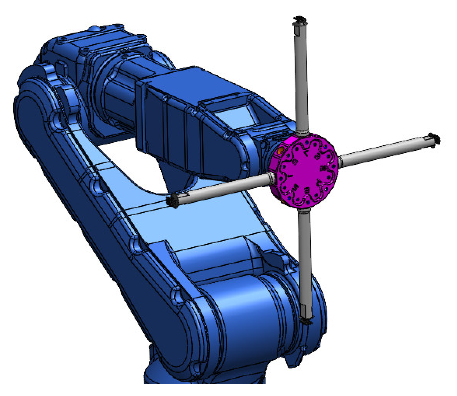
The process starts on the injection moulding machine. If all of the necessary conditions are met, the part is injected, and the machine opens the mould. The task of taking the part from the mould to the conveyor belt is carried out by a three-axis robot. Subsequently, the conveyor belt moves the parts forward to the two operators, where they are handled by each one, thus carrying out the visual check for possible defects, as well as the insertion of the clips. At this moment, if everything is in conformity, the parts are validated by the equipment and stored in the respective station to later be taken to the warehouse.
The three-axis robot responsible for carrying the part from the mould to the conveyor belt has a gripper attached to it, as shown in
Figure 5. Taking into account that this project constitutes an improvement of the production process associated with the MO.9163 mould, there is already a valid gripper to do the extraction.
2.1.2. Problem Awareness
With the incessant demand from the automotive industry for new and better products, having resources at a standstill symbolises a loss of profitability, jeopardising any company, regardless of its dimension. Taking into account the high evolution of the automotive industry, what today is a great novelty, within one or two years may already be completely obsolete, which leads to the rapid outdating of the produced equipment. Thus, the problems are:
Assembly process of components in parts is performed manually, occupying several labour hours;
Obsolete robotic cell;
Limited production capacity;
High costs in the insertion of clips on injected parts.
2.2. Defined Objectives/Requirements
The main objective was the improvement of an assembly process of parts for the automotive sector, taking advantage of out-of-service devices already used in previous applications. To accomplish these two goals, a reuse of existing equipment at the work development site was adopted whenever possible. For that, an analysis was performed on the existing stock of material, and a selection of what could still be used was performed. This made the whole project more profitable, more environmentally friendly, and could immediately increase profits. The objectives to achieve this goal were:
To develop an equipment capable of working autonomously, using the existing three-axis robot, with one type of components and two references;
To implement a system to feed the components, which are randomly deposited in the equipment;
To develop an auxiliary tool for the robot, capable of transporting the necessary components for a work cycle;
To create positioning systems for the parts in order to fix them during the assembly of the components;
To apply a component-detection system;
To apply a vision system for component-version detection;
To carry out the maximum reuse of existing materials.
With the implementation of the equipment in the production lines, the following results were expected to be achieved: reallocating the operators responsible for this assembly to other operations, increasing production capacity, and reducing production costs.
2.3. Proposed Concept
With the insertion of a robotic cell in the process, changes in the production must necessarily take place. Thus, the process needs to have a station between the injection machine and the conveyor belt: the cell, which becomes responsible for the tasks previously performed in the peripheral equipment. Consequently, the layout of the production line will change, and a proposal for this concept is presented in
Figure 6.
With the insertion of the cell, the order in which the process validation stage was carried out also changed. This validation used to be conducted by the peripheral equipment, and was now be executed by the robotic cell. All functions previously performed by the peripheral equipment were transferred to the cell, and the operator no longer has the function of inserting the clips, with the robot performing this task. Nevertheless, the operator still has to make a visual inspection of the part, but can immediately pack it for dispatch.
The hypothesis of reducing the machine cycle time was analysed, with the possibility of lowering it from 42 s to 38 s, since this was the cycle time of the three-axis robot. However, based on previous tests, this was impossible, as reducing the cycle time would deteriorate the quality of the product, causing the more-frequent appearance of defective parts in the injection.
3. Results
This section intends to present the final developed concept, thoroughly explaining the most relevant components of the system, as well as their functioning. This includes the development of the designed equipment, the new production process, and the results of the implementation, namely the cycle time reduction and the production rate increment.
3.1. Equipment Presentation
The main focus of this work was the production cell; nonetheless, in an initial moment it was necessary to consider several points that would define the unfolding of the whole project. The main parts of the cell and their functions are described below.
3.1.1. Gripper
The gripper used in this project, in contrast with the robot, had to be rethought based on the clips that would be inserted in the parts. Each part housed two clips, so the gripper had to be able to take the necessary number of clips to fulfil an insertion cycle, as shown in
Figure 7.
3.1.2. Feeding and Rejection Station
The feeder of this project must have cadence to deliver to the robot the required number of clips to perform the insertion cycle. Associated to the feeder, there must be a station where the robot is able to perform the tip-cleaning manoeuvre in case there is an error in some stage of the process. All of these systems must have a set of sensors associated to it that allow the robot to receive the necessary information to execute each operation.
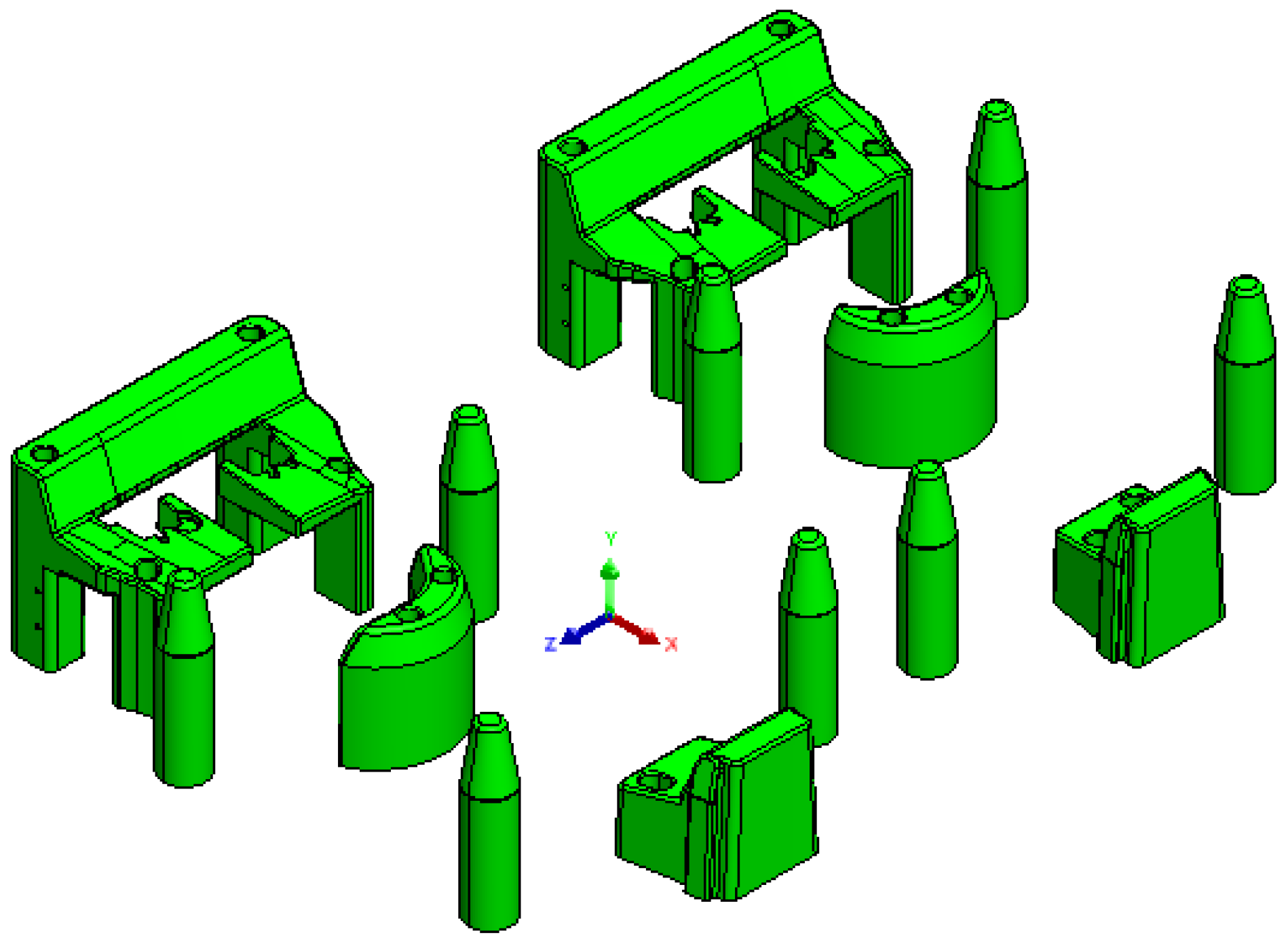
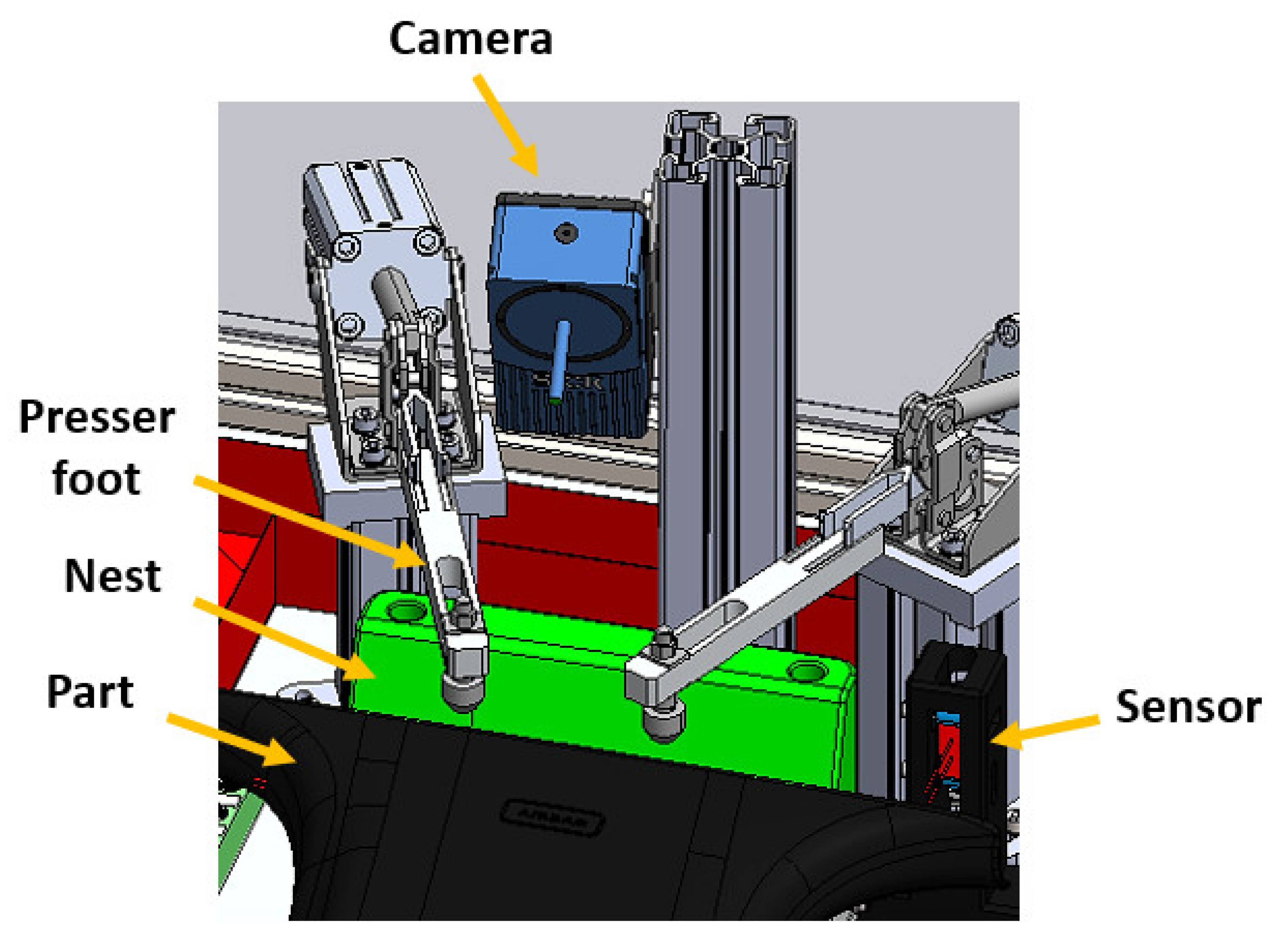
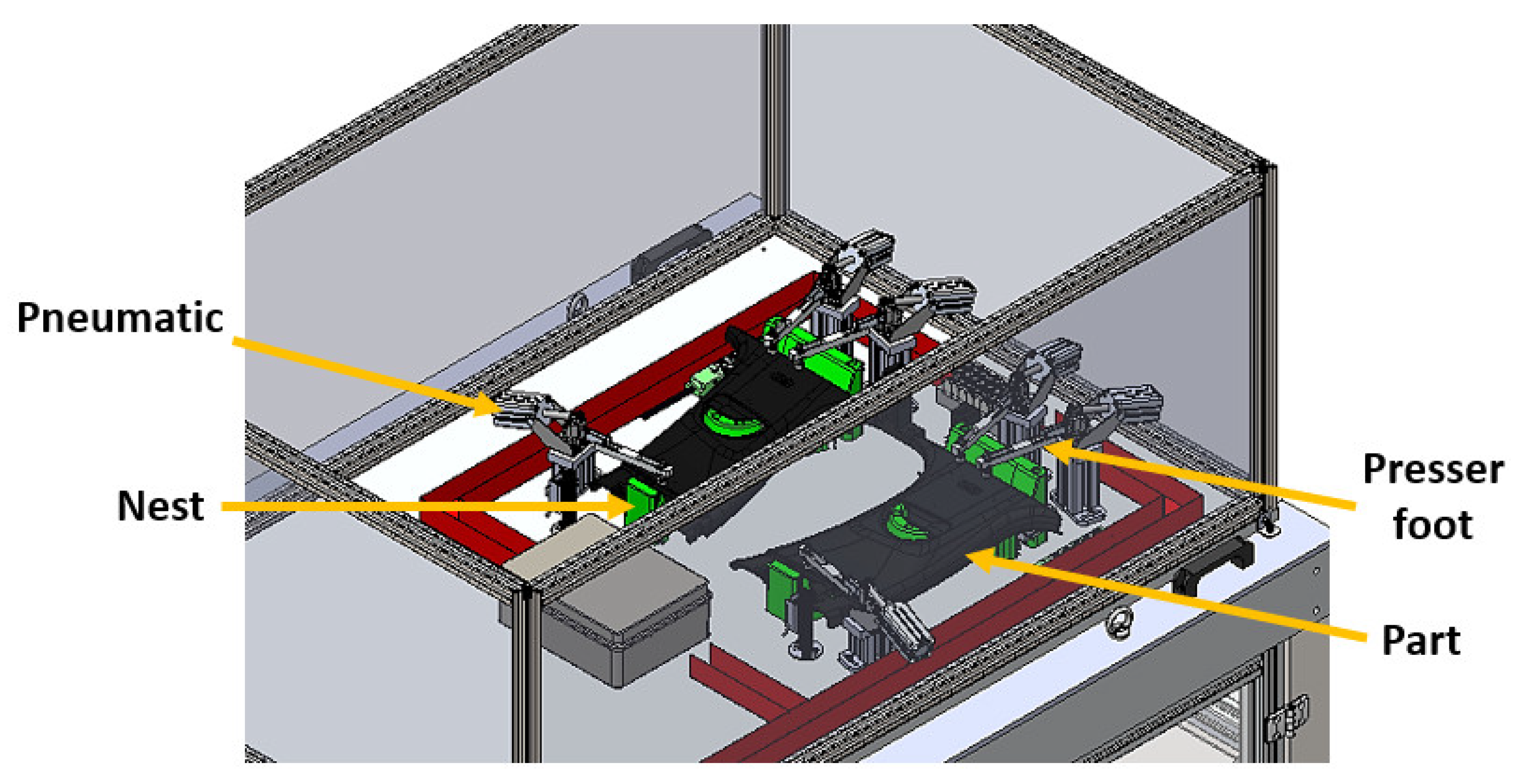
3.1.3. Cell Base
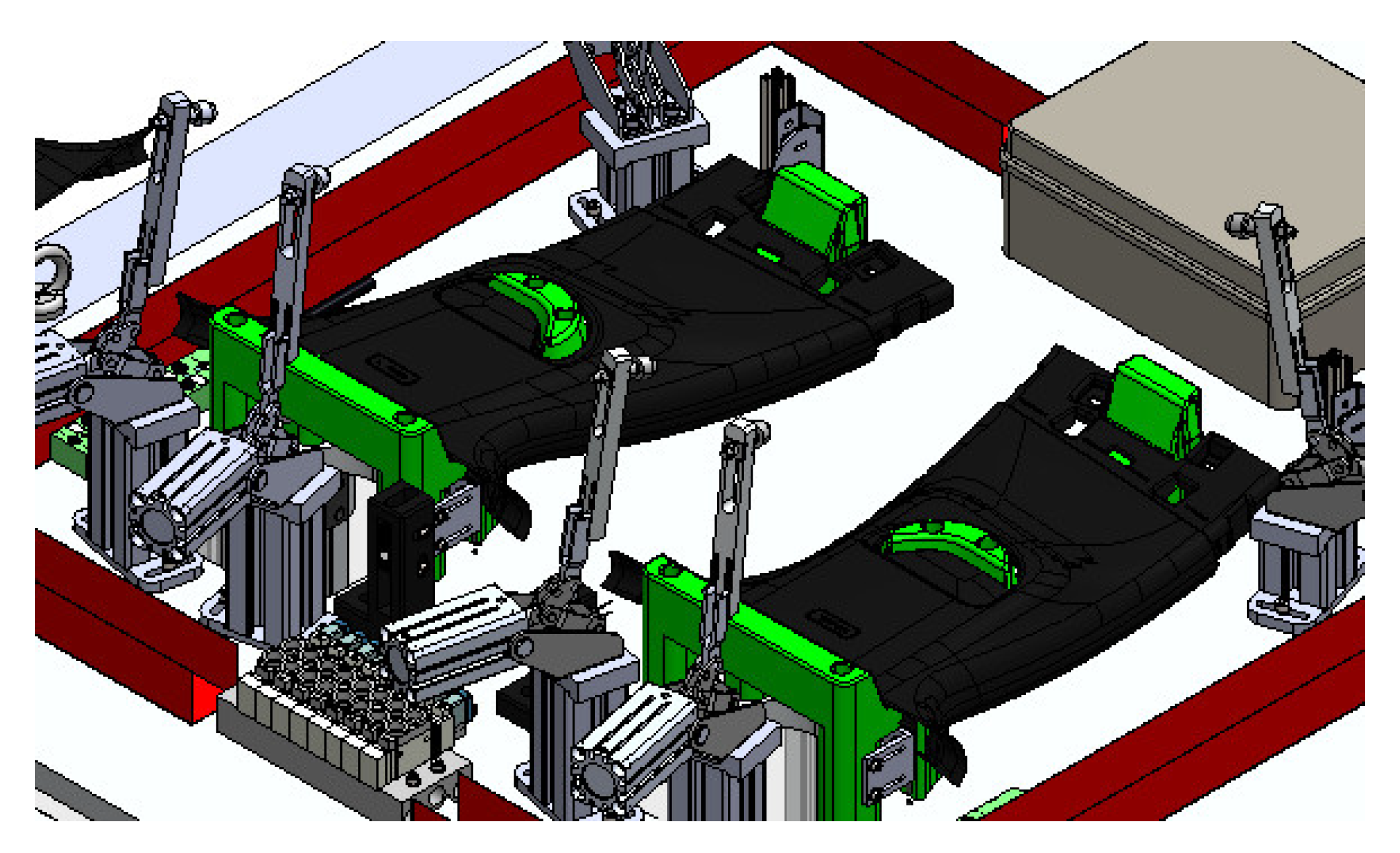
The base of the cell is the robot’s jig, i.e., this is where the parts for the robot to insert the clips will be housed. In order to allow the robot to perform this task when entering the base, the parts must be housed in blocks, ensuring the correct fixation of the part. These blocks, highlighted in green in
Figure 8, are usually referred to as nests.
When the part is dropped into the nests and the three-axis robot gives the order to start the cycle, a pneumatic system is activated which moves forward some stops that fix the part permanently, commonly known as presser foots, in order to reduce gaps in its fixing. To ensure the clamping in the most important points, there was at least one presser foot per clip, which was placed on the upper area of the part, in the clips’ insertion zone. In this place, the part had some cavities designated clip holders. In the base there were also several types of sensors that controlled the entire cycle and all actions to be executed by the robot.
3.2. Mechanical Project
In this project, there was no need for calculations or structural dimensioning, since the whole structure was already completed and tested, as the cell had already worked before. The main concerns were essentially related to the part the cell was going to work with. Even so, it was necessary to carry out a check-up on the security and means of access to the cell.
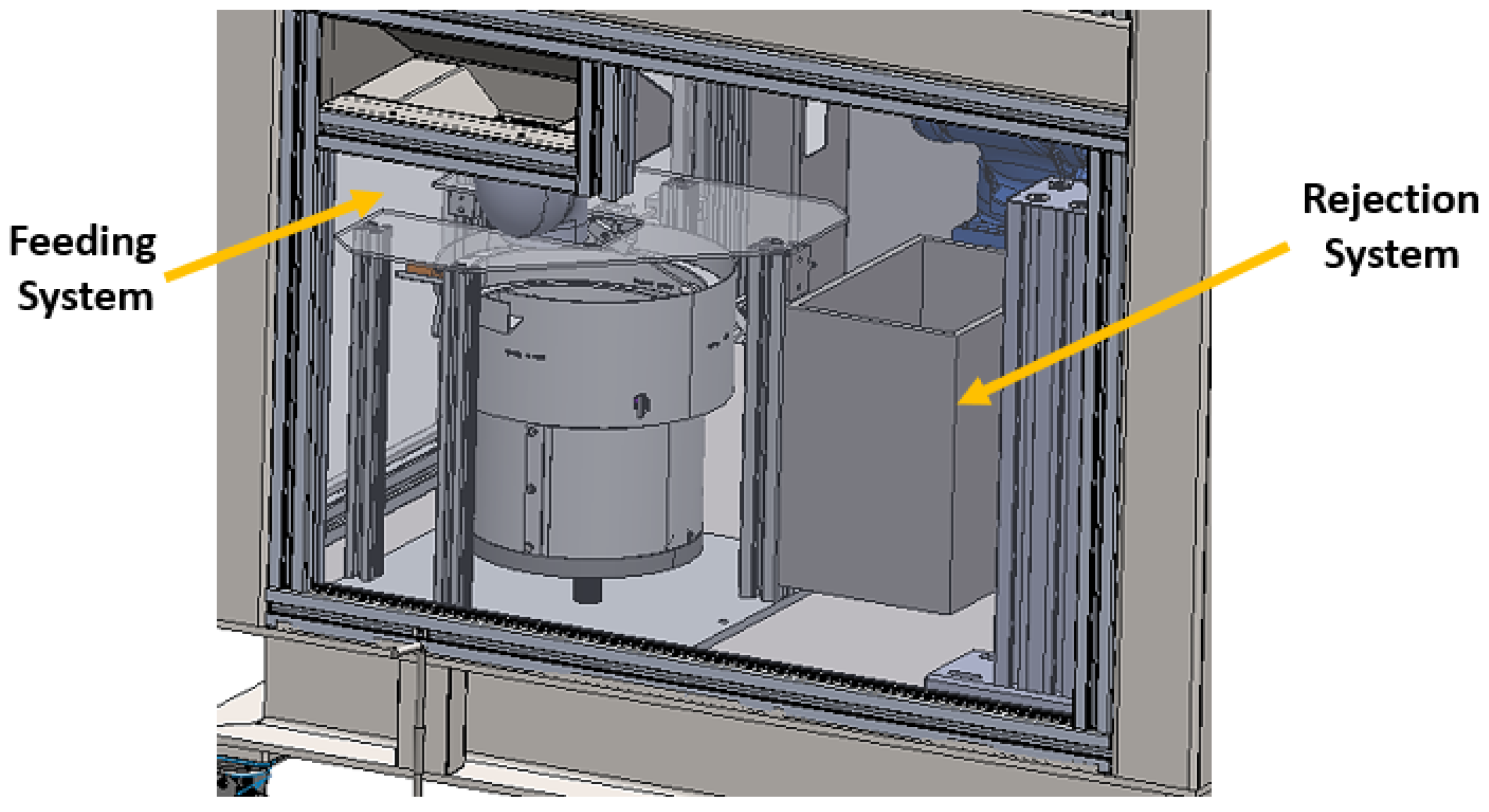
3.2.1. Feeding and Rejection System
The feeding system had the function of supplying clips to the gripper in order to allow the robot to execute its function. In addition,
Figure 9 also shows the rejection system, with a basket at the right side of the feeder.
This project’s main concern was to ensure the best location for the feeder, in order to reduce the number of movements needed by the robot to perform the feeding. After a careful analysis, a final decision was made, positioning it immediately below the location of the part’s nests. The rejection system must be right next to the feeder in order to store the clips which showed an anomaly in some stage of the process. In addition, there must be a window to safely allow operators to supply components to the feeder.
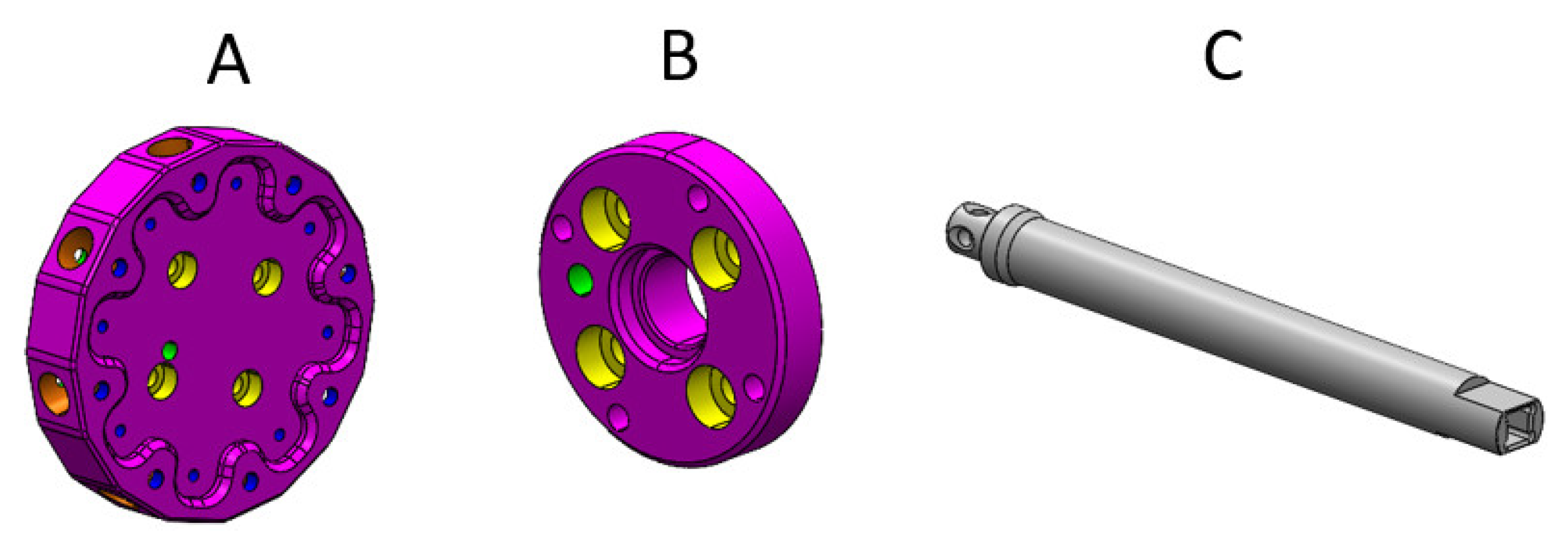
3.2.2. Gripper
Some parameters were defined so that the gripper design would meet the necessary requirements, namely (a) it needed to be able to load the needed number of clips for at least one insertion cycle, and (b) the gripper’s tips had to be at least 15 mm long to be able to perform the insertion. The gripper was the tool that the robot used to perform the required function, and consisted of three fundamental parts: the core, a protective disc for the robot, and the tips, shown in
Figure 10.
The core had the function of coupling all of the components, and the tips were the part of the gripper used to carry the clips to the insertion. The protection disk had the function of protecting the robot so that, if any accident happened, the damage was not focused on the robot. It also had a hole for the insertion of a pin, so that the gripper only fit in the robot in a single position.
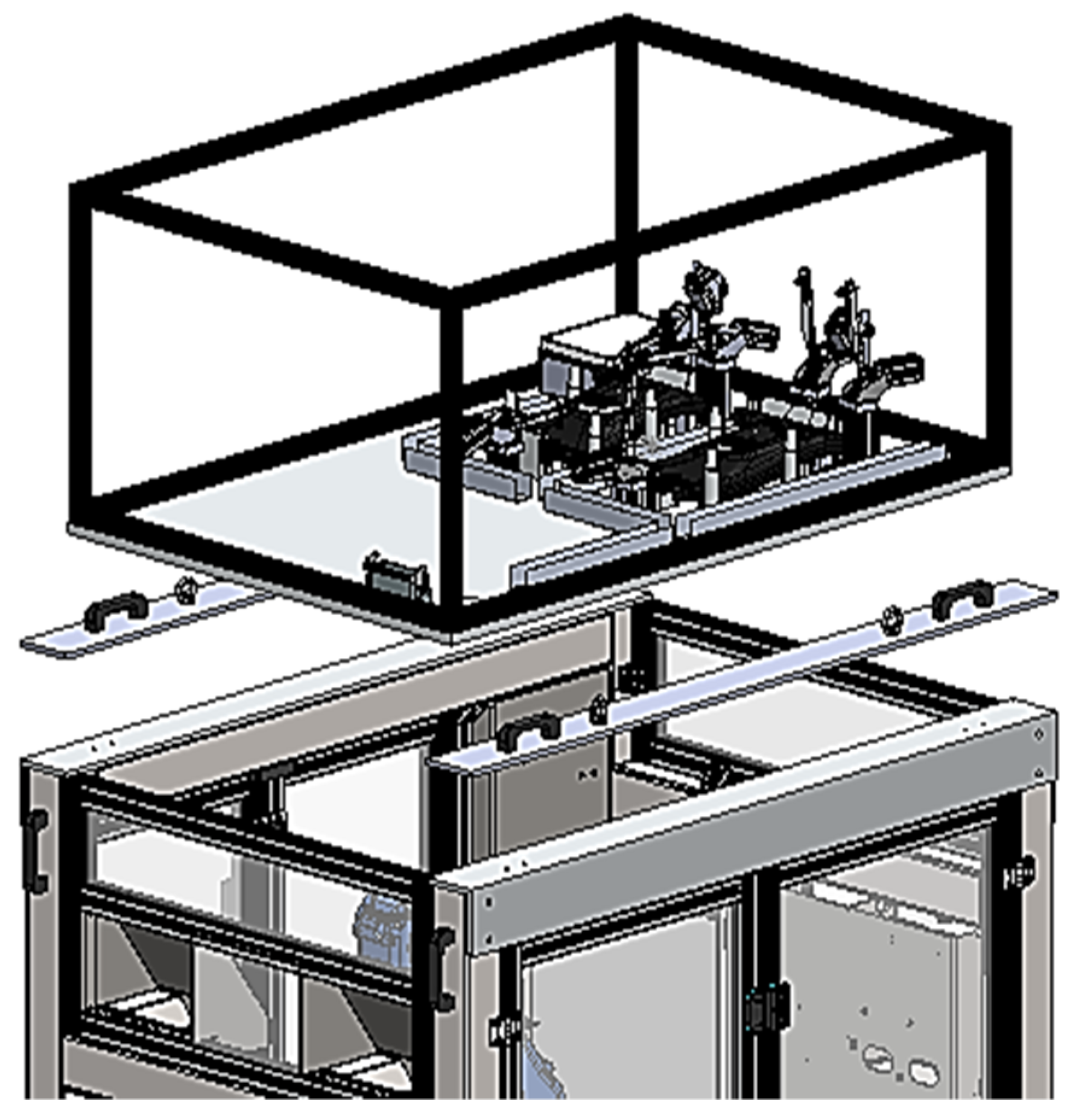
3.2.3. Base
The base was located at the top of the cell and was removable, as demonstrated in
Figure 11. Several systems were coupled to the base which were controlled by the robot in order to perform its function, having to obey to various parameters to be applicable in any cell.
The following are descriptions of the main requirements considered in the execution of the base:
Removable -> Each cell must be able to work with several moulds. Thus, the base should only be connected to the cell by screws and have lugs to facilitate its transport, for example with a crane.
Pneumatic supply -> Various mechanisms controlled by compressed air are coupled to the base. Therefore, the base must have a supply that is easy to disassemble, in order to simplify its operation;
Organisation -> In order to ease the work at the base of the cell, all electrical cables of the pneumatic hoses must be inside the rails. There must be a valve block where all pneumatic controls are performed. There must be an interface box where all the electrical connections between the base and the cell’s electrical panel are performed.
Nests
The nests are blocks of the base where the parts of the last injection will settle. The main concern with this design element was to ensure the best location and orientation of the blocks to facilitate the cycle of the three-axis robot. For this, a series of specifications were developed to which the nests (
Figure 12) needed to obey, allowing for the realization of the project: (1) the part, when pressed, does not allow any displacement; (2) the places where the clips are inserted must have a proper cavity, so that these zones do not have any degree of freedom; (3) the material of the nests must not damage the part; (4) they must be fixed with M5 screws, and there must be boxes for embedding them; and (5) the clip insertion zone shall have an area in which a sensor can be fixed in order to verify the insertion of the clip.
The more rotations the three-axis robot needs to make, the longer its cycle time will be. As the parts come out of the mould in a vertical position, it was mandatory that at least one rotation of the three-axis robot occurred before dropping the parts into the nests. Thus, taking into account that the cell would be in a perpendicular position to the conveyor belt, it was decided that the parts would settle at the base, in the same position as they leave the mould, but rotated to the horizontal.
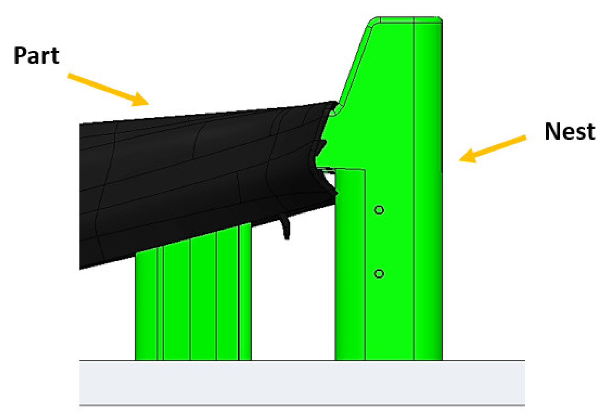
The nests had a cavity that housed the parts’ clip holder. Hence, the place where the clips would be inserted was covered by the edges of the part, as can be seen in
Figure 13.
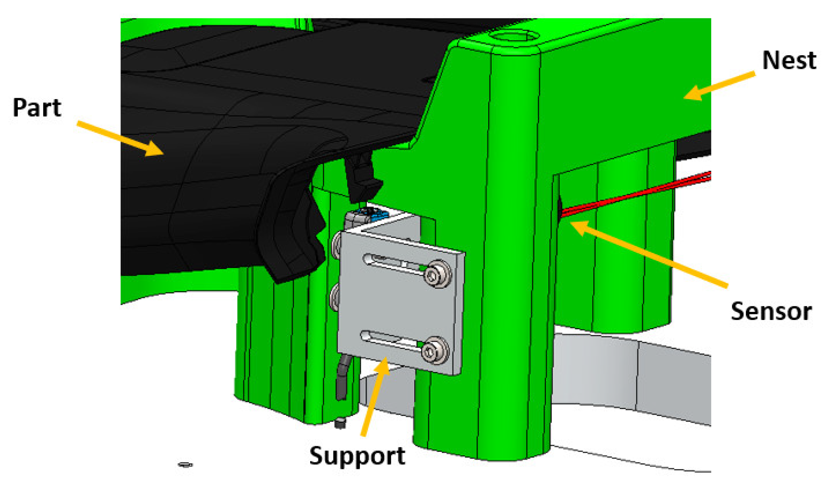
The detection of the clip in another place was not reliable because the detection must be made in the direction perpendicular to the insertion. Therefore, two threaded holes were drilled in the nests in order to embed a support for a sensor to be placed there, as represented in
Figure 14.
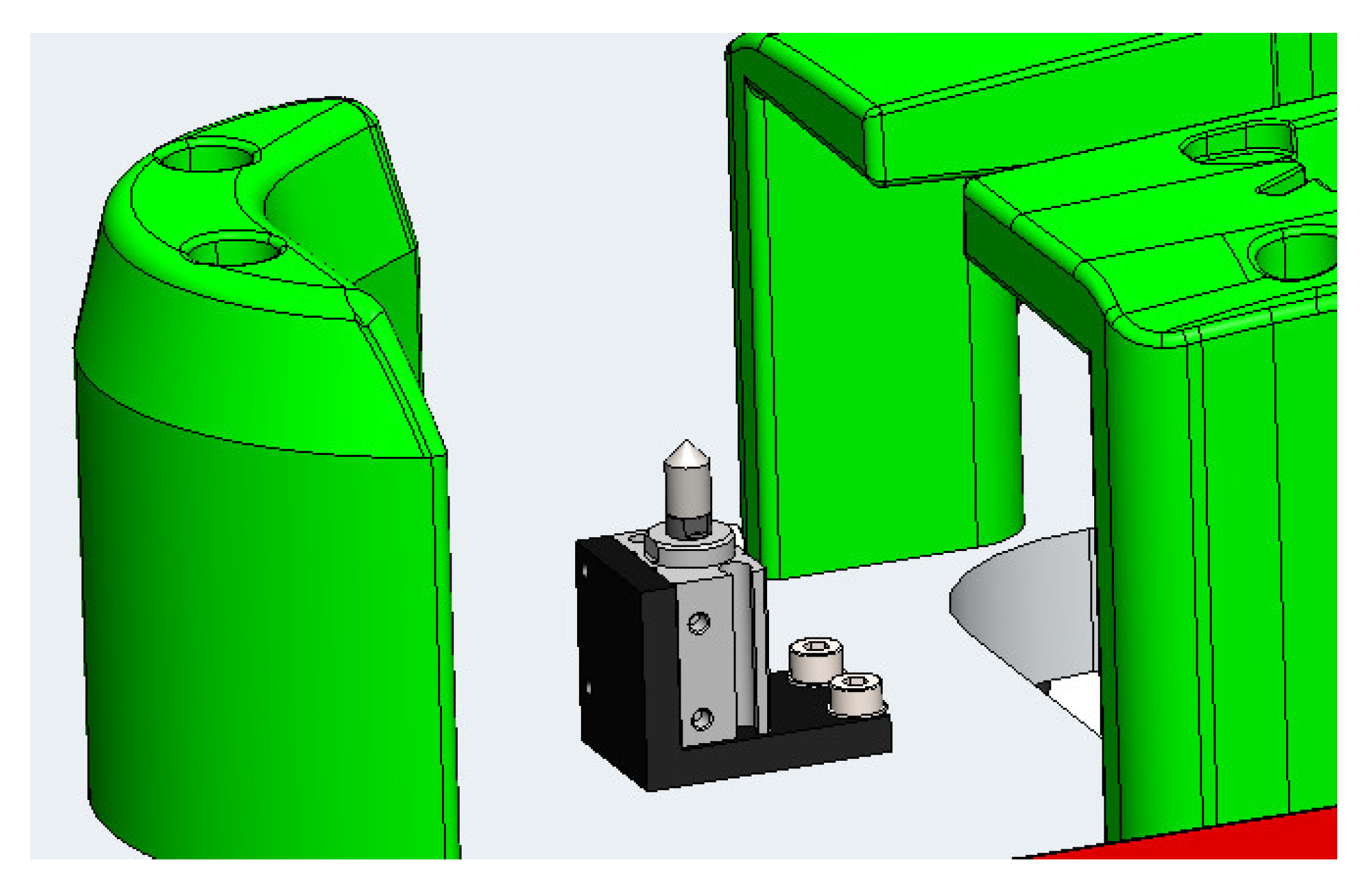
OK Peak
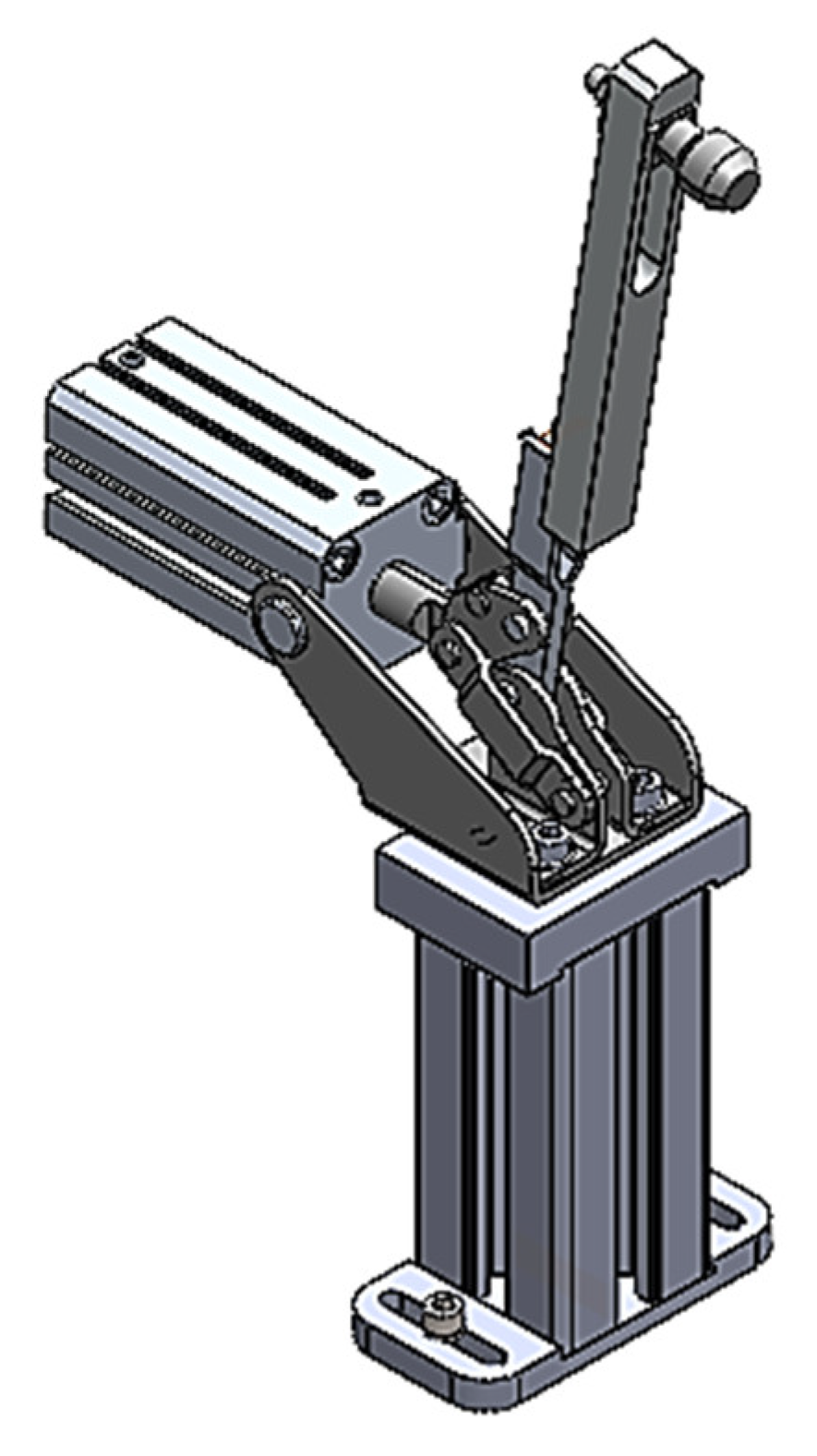
At the end of the robot insertion cycle, if everything complies with the quality criteria, the part is pierced in a specific place. A hexagon must be marked at the place where the validation peak is defined and, to do this, it is necessary to punch the mould in the area where the peak needs to be made, as not all the parts of the mould allow for the easy execution of this marking, such as the areas involving movements of some blocks in the mould.
In order to perform the OK peak, a small pneumatic was used and a support was created to ensure its fixation, the assembly of which is depicted in
Figure 17.
Sensor Holders
Taking into account the locations where it was essential to apply the sensors, it was necessary to create supports according to the existing needs.
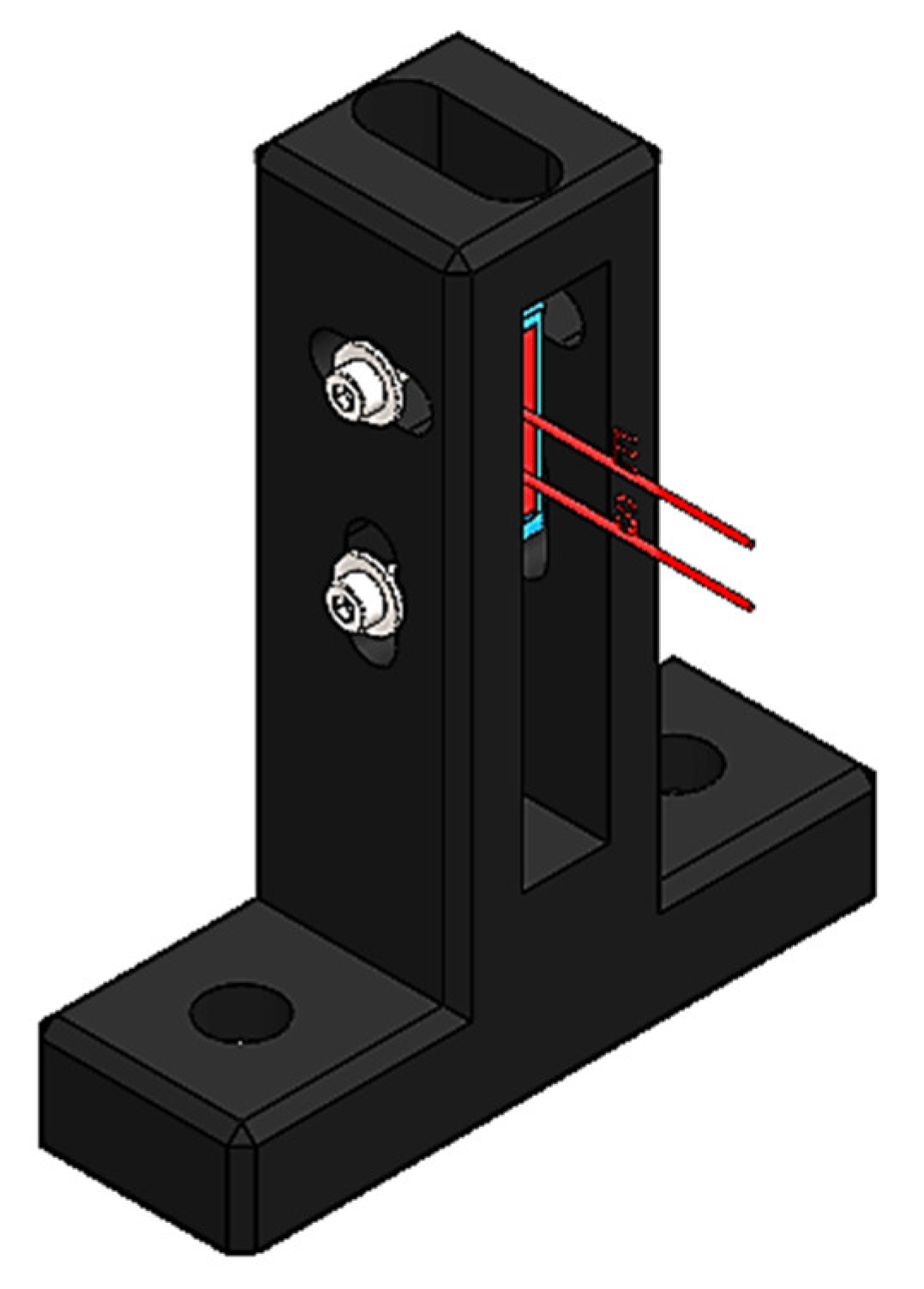
Incomplete Sensor
The ‘incomplete’ sensor is a sensor that identifies defective parts. A part is said to be incomplete when the injection process has not happened in the correct way and the part has not reached the final shape, defects which can be controlled using fine detection sensors. In order to overcome this situation, it was necessary to choose a support that would allow for some handling over the positioning of the sensor. In
Figure 18 it is possible to see the support and the sensor used.
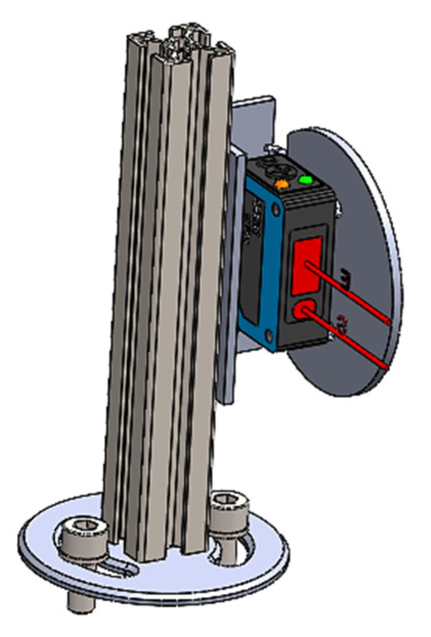
Part Presence Sensor
When the part falls into the nest, its presence must be detected. For this, a sensor whose detection field is larger needs to be used, since the position in which the part falls into the nest may not always be exactly the same. The support used for this sensor can be seen in
Figure 19.
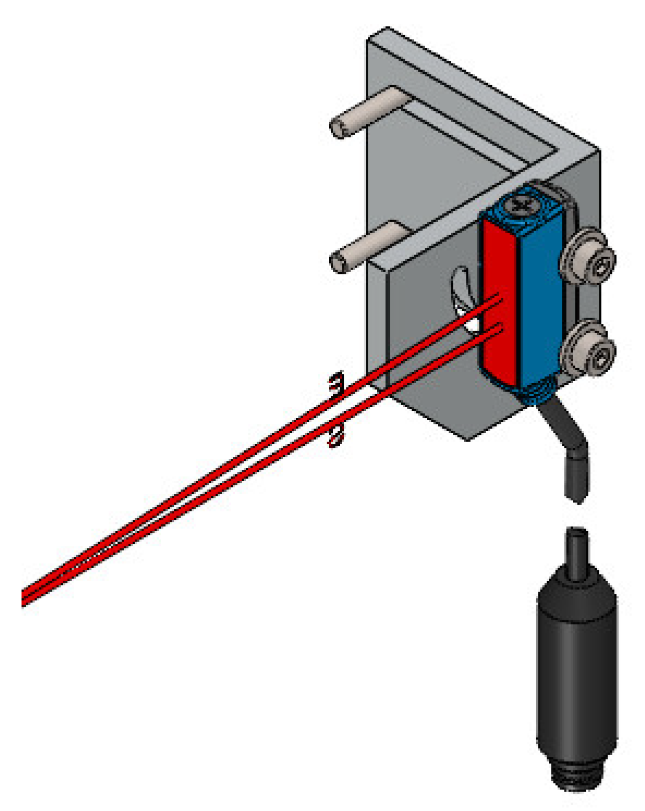
Clip Presence Sensor
The clip presence sensor for this project needed to be designed specifically for this purpose. As it was said before, the clip presence sensor would need to be embedded in the nests. Therefore, a specific support was designed in order to allow for manoeuvring in the sensor positioning. In
Figure 20 the sensor with the holder assembly can be seen.
Version Control System
The system used in this project for the version control is the same as was previously used in the peripheral equipment. This was installed under the nests where the operator places the part. At the time the part is placed, the version is automatically validated.
In this project, it was necessary to position the camera close to the nests of the part, and obligatorily close to the place where the version verification was carried out. Thus, a support was made, allowing for the positioning of the camera close to the place where the version is checked (
Figure 21).
3.3. Cycle Definition
The cycle starts when it is given the starting command. When the start button is triggered, the robot needs to check which is the base coupled to the cell (as mentioned before, a cell has the possibility to work with several bases) and, if it is the base corresponding to the mould working at that moment, the robot advances to the work routine of that base. The first task that the robot needs to perform is the cleaning of the gripper’s tips, otherwise a risk of collisions could occur. In other words, the robot needs to ensure the initial conditions so that it can start the work.
Once the condition that the gripper has no clips on its tips is guaranteed, the robot performs the feeding manoeuvre for each tip and then, with the gripper being ready to insert clips, the robot waits for the order to start the insertion operation. When the robot is in this state, it gives the machine ready signal to the three-axis robot, which tells it that the cell is ready to receive parts. Below, the conditions required for the machine ready signal to occur are listed:
Gripper loaded;
Part presence sensor turned off;
Incomplete sensor turned off;
Clip presence sensor turned off;
OK peak retracted.
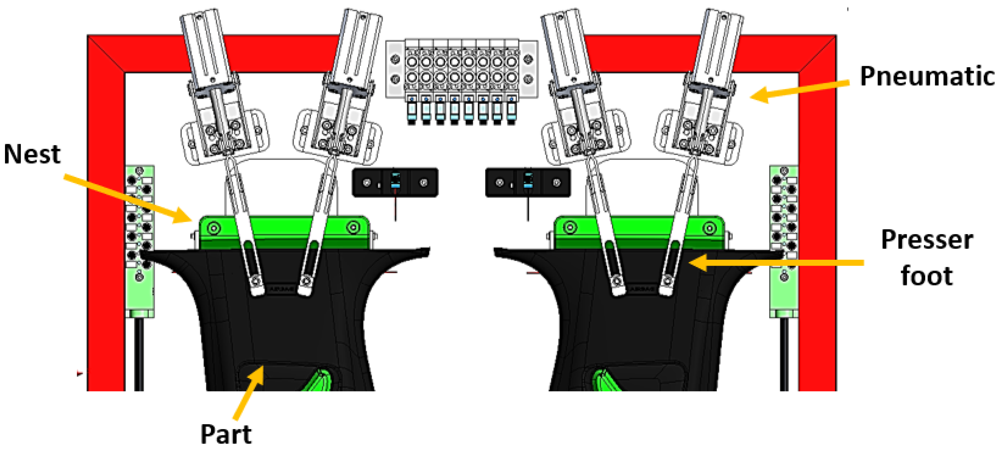
With the machine ready signal ON, the three-axis robot receives permission to drop the part from the last injection onto the base. The moment the part drops into the nests, the part presence sensors become active and the part is pressed, as represented in
Figure 22.
Once the part has been pressed, an initial status scan is carried out and, at the same time, it is assured that the part corresponds to the correct version. At this point, the robot verifies whether the parts are incomplete, whether they have clips already inserted, and whether the version being produced matches that of the production order. If any of these conditions are not met, the robot gives the end-of-cycle signal and the parts are rejected. In cases where all conditions are OK, the robot starts the insertion. For this to happen, the presser feet and the OK peak must be advanced, and the part presence sensor, the incomplete sensor, and the clip presence sensor must be turned ON.
When the robot finishes the insertion operation, a verification of the individual status of the clip presence sensors is performed and, if they are all turned ON, a signal is delivered which gives the information to the 3-axis robot that the parts are OK (
Figure 23). If the parts are not OK, this signal is not given. Subsequently, the robot emits the end-of-cycle signal.
With the end-of-cycle signal turned ON, the three-axis robot withdraws the parts from the base of the cell and, depending on the previous state of the part-OK signals, it performs the operation of depositing the parts on the conveyor belt or, in the absence of the part-OK signal (therefore only the end-of-cycle order exists), the robot rejects the parts. The moment the part presence signal turns OFF, the part-OK and end-of-cycle signals also turn OFF, and the cycle starts again.
3.3.1. Feeding Cycle
The main purpose of the robot feeding cycle is to prepare the gripper to allow the process to progress. The feeding cycle is associated with the rejection cycle, as both run in parallel and work together to ensure the proper gripper loading. The robot always runs the feeding cycle before performing an insertion, and the four tips have the same loading operation: the robot brings the tip close to the capture rail and confirms the state of a first sensor above the clip capture zone, which verifies the state of the tip. If the tip is empty, the robot performs the clip capture operation when a second sensor is active, which checks for clips in the rail. After the capture, the gripper returns to the previous level and checks if the procedure has taken place in the correct way.
In case any of these processes fail, the robot goes to the rejection station and cleans the tip. If in the previous cycle any of the parts is NOK due to the insertion failure of any clip, the robot performs the cleaning of the respective tip. In addition to the sensors that regulate the robot cycle, there are two more sensors able to check the status of the feeder, and these activate certain signals that warn the operator in case the cell’s work is compromised due to the feeder. These sensors detect the state of the feeder’s rail, and another one detects the state of the pan. If the rail is empty for a certain amount of time, the feeder sounds an alarm, as this may mean that the feed has jammed. The other sensor checks the status of the pan and, if this sensor is also active for a certain time, another alarm is issued, alerting the operator to supply clips to the feeder.
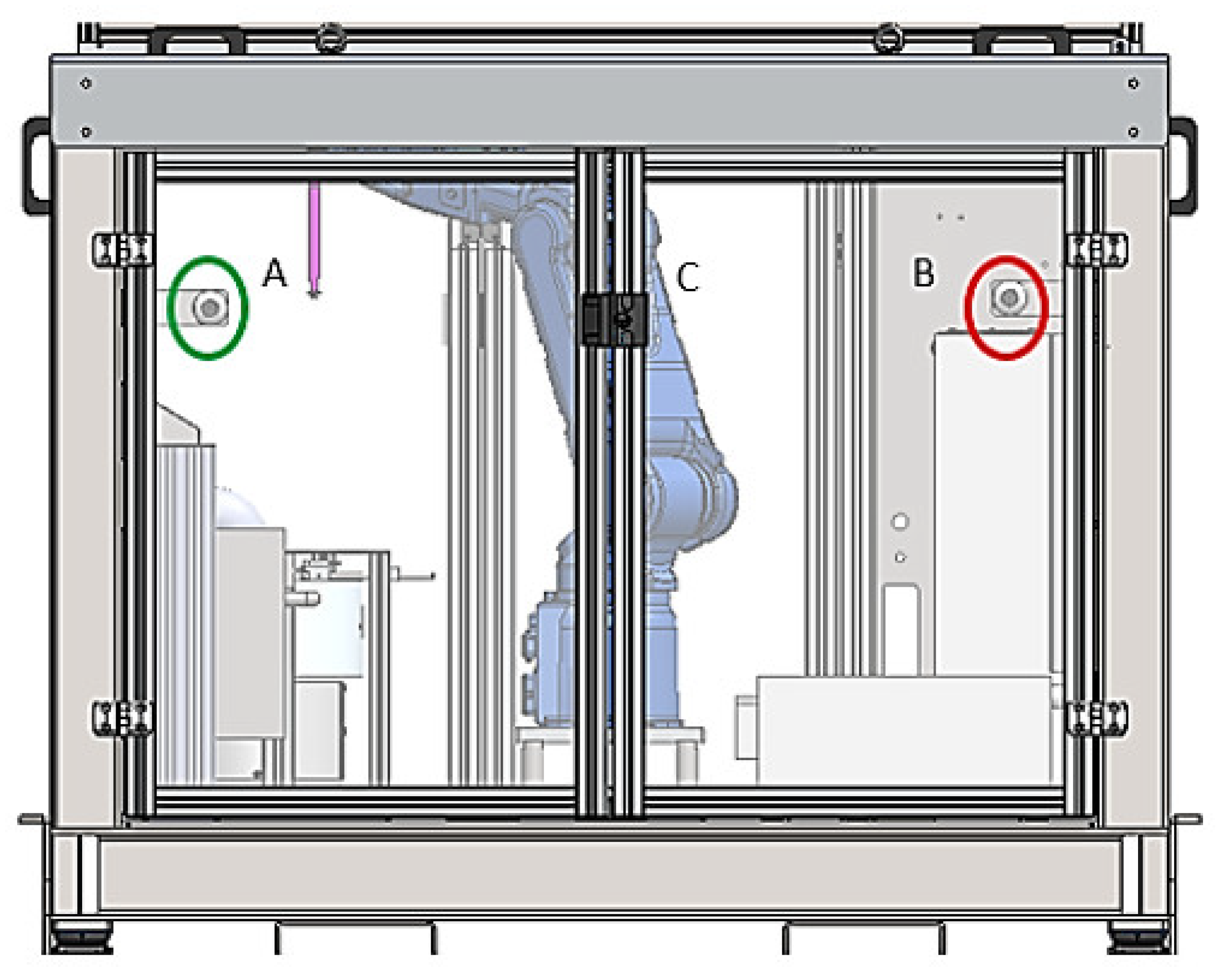
3.3.2. Cycle Signals
The robotic cell has two banners: one to alert the operator for the state of the feeder (A) and the other for the state of the machine (B). Based on the state of each of these systems, these banners make it easy for the operator to understand the state of the cell’s work. The system presented in
Figure 24 is located below the zone where the parts are positioned, the base, which can be seen in
Figure 11. The robotic arm acts below the superior module to have more space and to perform its tasks more easily. The banners A and B, also located below the base, are additional devices developed to help the operator with the whole process.
Depending on the colour of the cell banner, the operator receives a different alert. Steady yellow indicates machine ready, flashing yellow is the insertion cycle, steady green is part OK, and steady red is part NOK. In the case of the feeder, the same rule applies, with flashing red for missing springs and steady red for jammed feeder.
3.3.3. Insertion Cycle
The insertion cycle is the completion of the entire cell process. Before the three-axis robot drops the part into the cell, it verifies the status of the machine-ready signal. If it is missing, the part cannot be dropped into the cell.
When the necessary conditions exist, the three-axis robot drops the part into the cell. Firstly, the robot scans the state of the ‘incomplete’ and clip presence sensors. If either of these is turned ON, the parts are immediately rejected, and the end-of-cycle order is given, with the three-axis robot rejecting the parts. If neither of these conditions is ON, the robot advances to the insertion cycle.
At the end of the insertion, the robot rechecks the status of the clip sensors, and if they are all turned ON, the parts-OK signals are activated, and then the cycle ends. These signals are active as long as the part presence signal is turned ON. When the three-axis robot removes the parts from the base, these signals automatically turn OFF and the cycle restarts.
3.4. Equipment Costs
One of the main objectives of this project was to make the maximum reuse of previously used material not needed at the moment. However, even so, it was necessary to resort to suppliers to obtain certain components, the lack of which could not be made up for with the recovered material. The general costs associated with the acquisition of the equipment are present in
Table 1, totalizing a value of 16,650 €.
3.5. Implementation Results
Some of the gains obtained by inserting the cell in the process are described below:
There will no longer be stoppages which were mandatory before with the production depending on two people, thus improving the process yield;
In the short–medium term, it is expected that the quality of the process will improve, thus reducing costs with possible non-conformities in the production;
Reduction of the probability of non-conformities due to human fatigue;
With the reallocation of one worker, a cost of 1300 €/month will be saved, and this value can increase if the cell operates for more than one shift per day.
In addition, an overview of all of the reused material is presented: robot and controllers, electric panel and components, protective frame and rims, the aluminium base protection frame, and all of the pneumatic materials (valve block, accessories and 33 pneumatic ramps).
The costs of the equipment, when compared with the reused material and the future gains of having the cell inserted in the process, will be recovered after less than 12 months, if only the gain obtained by the reallocation of an operator is accounted for. It is expected that the quality of the process keeps improving with the robotic cell in production, which will also be reflected in the gains that will be obtained.
It should be noted that the productivity gain ensured by this project has no direct implications for the production cycle, given that the injection cycle is optimized and cannot be reduced. However, just regarding the fact that there are no disturbing factors of the normal production cycle downstream of the injection, i.e., during the inspection and assembly of clips, provides that 16% of the useful production time is not wasted. This is because when the downstream in the inspection and assembly operations decreases, this is implied to stop the injection production cycle, preventing the congestion of the subsequent processes or the use of extra labour to comply with the production schedule. In addition, there is even greater assurance that the product is properly inspected, that is, the inspection is not affected by human fatigue, thus resulting in a more coherent and effective filtering of non-conformities.
4. Discussion
The results obtained show that there is a series of opportunities for improvement in the industry, which must take advantage of them in order to increase economic sustainability, reduce dependence on human labour, and increase quality. On the other hand, the greater sensitivity that exists to environmental issues will certainly influence many decisions, as it is not economically sustainable to replace some equipment prematurely without there being opportunities to reapply it in situations where it can still be useful [
41,
43]. The work now developed clearly shows that it is possible to reconcile projects to increase productivity with the reuse of devices and components previously used in other projects without any loss of competitiveness in their reuse, thus benefiting the environment, i.e., environmental sustainability.
The concept now presented is in line with other works previously performed, where robotics and conventional automation were used together with a view to increasing productivity and quality assurance. In fact, this solution is perfectly in line with some solutions previously found by other authors to solve problems related to different products, but in which the objective was similar: to increase productivity. Examples of this are the works carried out by Costa et al. [
18], Silva et al. [
31], and Castro et al. [
42]. In fact, Castro et al. [
42] also reused a robot that was already out of service, expanding its potential through the possibility of moving this robot on a track, thus increasing its field of action and giving it a new industrial utility where the speed of the execution of tasks was not the main objective, as in the case of the present project. Obviously, the environmental issue is important, but reuse also represents a significant saving in terms of the investment needed to increase the degree of automation of a given process. In the case presented here, and through a relatively rough calculation, the saving in the salary that should be paid to an operator during a year in a work shift is greater than the investment that is necessary to make in this project, which leads to a ROI (return on investment) in less than 12 months. This value fits perfectly with what is usually accepted by industrial companies, which normally consider a maximum of 36 months, in practical terms, to find the project economically viable in view of the estimated life of each product in production. Comparing the ROI period with other works, it is possible to verify that Magalhães et al. [
12] achieved an ROI of around 8 months for the automation of a process connected to CNC wire bending equipment, without resorting to any reuse of equipment or components. Furthermore, the complexity of this concept is more modest than that performed in this work. On the other hand, Silva et al. [
8] presented a ROI of 5 months for the automation of a process linked to the over-moulding of metallic wires with plastic, which automation involved the orderly arrangement of wires for collection with a gripper, and a dedicated gripper design for feeding and collecting the product. However, the value of the ROI obtained through this work (12 months) is lower than several other works where automation also aimed to increase the productivity and competitiveness of products, although without environmental concerns. Santos et al. [
44] developed a conventional automatic system for the textile industry and achieved a ROI of 14.5 months. On the other hand, in the work developed by Silva et al. [
31] using the incorporation of a new robot and of all the conventional automation around it, the estimated time for the ROI was 21.5 months, thus showing the difference in the period of ROI that the reuse of an existing equipment can bring in terms of economic advantage. Often, the need to increase productivity is accompanied by the need to guarantee quality levels that are adequate to the requirements imposed by the market. This was also felt in this work, similar to what was also reported by Costa et al. [
14]. Some limitations of this work are that the total cycle time can still be improved; however, this depends on the injection cycle time, so there is always a minimum value which cannot be lowered. In addition to this, the position in which the clips are attached can also represent a problem in other works, so the work represented in this article is just an example and has to be adapted when considering other cases.
5. Conclusions
SMEs still have an immense field of progression in terms of productivity gains in component production and assembly operations. Robotics, coupled with conventional automation, is the most suitable way to produce increases in productivity and ensure the increasingly high level of quality demanded by the market. The deactivation of some end-of-life projects leads to the decommissioning of countless devices and components that can still be reused. If projects to increase productivity and quality can take into account devices that are no longer useful in previous projects, the cost of the investment necessary to automate processes and the corresponding increase in productivity and quality can be reduced. Thus, the competitiveness of products benefits in parallel to the environment, as the creation of industrial waste and the consumption of natural resources is minimized.
This work aimed to show that it is possible to create new concepts around the need to increase the productivity and quality of assembly operations underlying the injection of plastic parts for the automotive industry, taking into account devices and components previously used in other projects. The concept is shown through a case study linked to the production of parts for the interior of automobiles in which, after injection, it is necessary to inspect and install clips before the product is packed and sent to the customer. Taking advantage of a robot previously used in another project that is already finished, solutions were created based on conventional automation that complemented the action of the robot, giving rise to a production cell coupled to a plastic injection machine that became much more autonomous in relation to human work, guaranteeing higher levels of production and ensuring a higher level of quality because the control operation is no longer subject to human fatigue.
Given that the new concept completely dispenses one of the operators, as well as almost completely dispensing with the second one, even considering only the dismissal of the first one it is possible to have a return on investment in less than 12 months. This value fits perfectly with the financial performance normally required by industrial companies to consider the investment as profitable, taking into account the estimated life of each manufacturing project. This value is achieved thanks to the use of a robot from a project that has been completed in the meantime, and which has sufficiently attractive characteristics to empower the concept of increased productivity studied here. As previously mentioned, it was not the main objective of the case study used to validate this concept to increase the production rate, since this is imposed by the injection cycle and was already optimized. Nevertheless, the application of this concept prevents the process from having downstream breaks during inspection and assembly operations that were performed manually after the injection cycle. Hence, no productivity gain in terms of cycle is indicated, but taking into account the history of production breaks in manual operations in the past, which congested and forced the injection process to stop, it can be stated that they were around 16 % of the production time.
Therefore, in addition to achieving the desired levels of productivity and quality and reducing the dependence on human labour, it is also possible to take care of the environmental aspect, minimizing the consumption of natural resources and preventing out-of-use equipment from being recycled, thus resulting in energy consumption so that it could be turned into something useful again. This work intended to bring a novel concept of reuse of industrial devices that are still capable of giving a strong contribution to the increase of productivity and quality and minimizing investment costs, i.e. making them more attractive in financial terms, as well as to the environment.


 ,
, 


