Article

Permeability-Enhancing Technology through Liquid CO2 Fracturing and Its Application

1
Key Laboratory of Comprehensive Utilization of Nonmetallic Mineral Resources in Guizhou, School of Mining, Guizhou University, Guiyang 550025, China
2
College of Aerospace Engineering, Chongqing University, Chongqing 400044, China
*
Authors to whom correspondence should be addressed.
Sustainability 2022, 14(16), 10438; https://doi.org/10.3390/su141610438
Submission received: 23 June 2022 / Revised: 1 August 2022 / Accepted: 17 August 2022 / Published: 22 August 2022
(This article belongs to the Special Issue Advances in Dynamic Hazards Prevention in Underground Mines)

Abstract

:
Liquid carbon dioxide (CO2) phase change fracturing (LCPCF) is an innovative technique to improve the efficiency of gas drainage from low-permeability coal seams of high gas content. However, fracture sprouting, extension and displacement changes of coal under LCPCF need further study, and corresponding field tests are also lacking. Therefore, a mechanical model based on the thermodynamic theory of CO2 phase change is developed in this paper. Then, the pressure change characteristics, crack propagation and displacement change of coal subjected to LCPCF were analyzed through numerical simulation. In addition, the permeability-enhancing effect of the field LCPCF test was analyzed. The results obtained from the numerical simulation show that during the LCPCF process, the crack-generation process changes with pressure as follows: microfracture–numerous microfractures–major macrofracture–macrofractures. During the development of fractures, the stress is incompletely symmetrically distributed in coal centered on the fracturing borehole. The failure occurs stochastically in the coal in the vicinity of the fracturing borehole at first, and then it gradually propagates to the inner seam of coal as the gas pressure increases. The following result can be obtained from field experiments: the permeability coefficient of coal seams after increasing the permeability through LCPCF is 2.60~3.97 times that of coal seams without presplitting. The average concentration of gas extracted in coal seams within the zone having undergone an increase in permeability through liquid CO2 fracturing is 2.14 times greater than that within the zone without presplitting. The average pure amount of gas extracted within the zone having undergone an increase in permeability through LCPCF is 3.78 times greater than that within the zone without presplitting. By comparing coal seams before and after fracturing in the field test, it can be seen that the LCPCF presents a favorable effect in increasing the permeability of low-permeability coal seams. This provides an effective approach for increasing the permeability of coal seams in coal mines with similar geological conditions.

1. Introduction

China is a country that is abundant in coal resources, with many reserves and a variety of types; however, the conditions of the occurrence of coal seams are complex [1,2,3]. As China’s major energy source, coal will remain the main fuel consumed in the country for some time to come [4]. As an associated resource, coalbed methane (CBM) is regarded as a potentially available resource [5,6]. Enhancing the efficiency of CBM extraction not only avoids the waste of resources, but also ensures the safe and efficient production of coal mines [7,8,9]. As coal resources are constantly mined and the degree of mechanization of coal mines is constantly improved, the mining depth of coal mines has continually increased and deep coal has been mined in a majority of large-scale and medium-scale coal mines [10,11]. The geostress, gas pressure and gas content in coal seams also constantly grow with the increasing mining depth of coal mines [12,13,14]. Moreover, the mining becomes increasingly difficult due to high gas content and the risk of coal and gas outburst, which presents a great challenge for gas control in mining areas [15,16,17]. Therefore, the use of coal seam anti-reflection measures is of great significance for improvement, resource utilization, the recovery rate of CBM, and coal mine safety production [18,19,20,21].
Some external load stress technologies, such as hydraulic fracturing, hydraulic punching, and loose blasting, increase the permeability of coal seams and improve the efficiency of CBM mining [22,23,24,25,26,27]. However, these techniques have some disadvantages. For example, hydraulic fracturing and hydraulic cutting have the ability to consume a large amount of water resources, easily cause water damage, and seriously inhibits the extraction efficiency of CBM through the water resistance effect [28,29,30,31]. The loose blasting can easily form areas of concentrated stress in the coal seam, thereby increasing the possibility of accidents [32,33]. In order to overcome the above shortcomings, some researchers have proposed non-aqueous fracturing technology [34,35,36,37]. Among them, LCPCF is a technology developed in recent years to improve the gas extraction rate of low permeability coal seams [19]. Developed in recent years, the permeability-enhancing technology utilizing liquid carbon CO2 fracturing aims to increase the efficiency of gas drainage from low-permeability coal seams. This technology, being simple, safe and reliable, can greatly improve the efficiency of gas drainage, reduce the gas content and gas pressure in coal seams and effectively eliminate the risk of coal and gas outburst [38,39]. It is worth mentioning that although liquid CO2 is usually injected as the fracturing medium in engineering practice, it is likely to transition to a supercritical state when the pressure and temperature exceed the CO2 critical point (7.39 MPa and 31.09 °C) [40] in deep coal seams. Therefore, in this paper, 7.39 MPa is taken as the initial pressure. Supercritical CO2 is expected to be an ideal fracturing medium because of its low viscosity (similar to CO2 gas) and high density (similar to liquid CO2) [41]. Additionally, Sc-CO2 has higher adsorption properties and diffusivity in coal [42,43,44], it is more likely to adsorb with coal to prompt gas desorption. Meanwhile, the injection of CO2 into coal sequestration to reduce greenhouse gas emissions is one of the potential applications [45]. Therefore, it is of great practical importance to study the injection of CO2 into coal.
So far, many results have been achieved in the research on LCPCF. On the theoretical side, researchers [46,47,48] found that there is a competitive adsorption mechanism between CO2/N2/CH4, and the adsorption capacity of CO2 is approximately 3 times that of methane and 7 times that of nitrogen. Therefore, injecting CO2 into the coal seam can better recover CH4 from coal and improve the recovery efficiency of CBM. Li et al. [49] studied the dynamic characteristics during the phase change of liquid phase CO2 and obtained the strain and stress parameters of the coal body. The studies of Dai et al. [50] and Mosleh et al. [51] showed that the change of porosity during LCPCF is the reason to increase the gas permeability. Zhu et al. [32] suggested that CO2 stress blasting could not only reduce the stress concentration of coal around the borehole, but also improve the permeability coefficient of coal. In order to clarify the effects of LCPCF technology on the microstructural damage characteristics and permeability characteristics of coal, a large number of studies have been carried out by related scholars [52,53,54,55]. These studies showed that after the coal was treated with LCPCF, the structure of the coal body was significantly damaged and a large number of pores/fractures were generated, which increased the permeability of the coal seam and provided a flow channel for the desorption and transport of coalbed methane. Subsequently, further studies [56,57] were carried out by related scholars, and it was found that although LCPCF had a significant effect on the pore/fracture structure of coal, its effect depended on various factors, such as coal rank, burial depth, and distance from the fracture borehole. Liu et al. [58] verified through numerical simulation that CO2 injection into coal has a positive effect on improving CH4 production. In terms of field application, Xia et al. [59] injected CO2 into a low-permeability field and found that the recovery rate was increased by 1.3–1.4 times compared with the original. Wen et al. [60] found that the effective radius of influence of LCPCF technology could reach 5–7 m, and the gas extraction concentration was increased by 2–3 times after CO2 fracturing. In summary, LCPCF technology is an innovative technology for improving coalbed methane recovery, which has important research value and broad application prospects. However, further research is needed on the fracture sprouting, expansion and displacement changes of coal under the action of LCPCF.
In this paper, based on the CO2 phase change thermodynamics theory, a mechanical model was established to numerically simulate the CO2 fracture expansion law and the coal body displacement and stress change law, and to reveal the mechanism of LCPCF for coal seam unloading and increasing permeation. In addition, most of the current studies were conducted under laboratory conditions and lacked field test data, which thus could not accurately reflect the effect of LCPCF in the field. Therefore, a field application test was conducted in the 2131 transport road of Xiangshui coal mine in Panzhou, Guizhou province, and the changes in the permeability coefficient, natural flow decay coefficient, gas extraction concentration and pure volume of extraction in the borehole before and after the permeability enhancement were discussed. This study provides a basis for promoting the use of CO2 to enhance CBM extraction.

2. Methodology

RFPA2D-Flow is a realistic rupture process analysis system with elastic mechanics as the stress analysis tool and elastic damage theory and this modified Coulomb damage criterion as the media deformation and damage analysis module. The stress analysis is carried out by the finite element method, and the mechanical response of each calculation step under the action of external load and environmental factors (loading, excavation, change in load and displacement boundary conditions, etc.) is completed based on the effective stress principle. In the simulation process, the material medium model is discretized into a numerical model composed of fine-scale basis elements, and the material medium is an isotropic, fine-scale, elastic brittle, or brittle plastic medium. The modified Coulomb criterion is applied to describe the critical point of the phase transition of the primitive, and the primitive element is a linear elastomer before and after the phase transition. The mechanical properties of the primitive element change irreversibly over the course of its development, and the software introduces an appropriate criterion for its destruction (phase transition criterion) and a damage law to more accurately model the process of change. In the process of establishing the connection between the mechanical properties of fine and macroscopic media, the software assumes that the mechanical properties of the discretized fine primitive elements obey some statistical distribution law. In the solution process, the software uses the linear elastic finite element method as the stress solver and analyzes the stress and strain states of the model according to the linear elastic stress and strain solution method of the primitive elements in elastic mechanics.

2.1. Model Construction and Parameter Setting

2.1.1. Model Assumptions

RFPA2D-Flow is based on the following assumptions.
(1)
The seepage process in the coal rock satisfies the Biot consolidation theory and the modified Terzaghi effective stress principle.
(2)
The fine-scale unit body in the coal rock is elastic brittle and has residual strength, and its mechanical behavior is described by the elastic damage theory with the maximum tensile strain criterion and the Mohr Coulomb criterion as the threshold conditions for damage.
(3)
The permeability of the fine unit body in its elastic state satisfies the relationship between permeability and the stress–strain function, and the permeability increases after damage rupture.
(4)
The structure of coal rock is non-uniform, and the damage parameters of the fine-scale unit body of the coal rock satisfy the Weibull distribution, as in Equation (1):
φ ( a , m ) = m a 0 a a 0 m 1 exp a a 0 m
where a is the parameter of the fine unit of material (coal rock), such as the modulus of elasticity, compressive strength, tensile strength, Poisson’s ratio, permeability, etc.; a 0 is the statistical average of the parameters of the fine unit; m is the property parameter of the distribution function, i.e., the non-uniform coefficient, the physical meaning of which reflects the uniformity of the material medium; and φ ( a , m ) is the statistical distribution density of the physical properties x of the material matrix element.

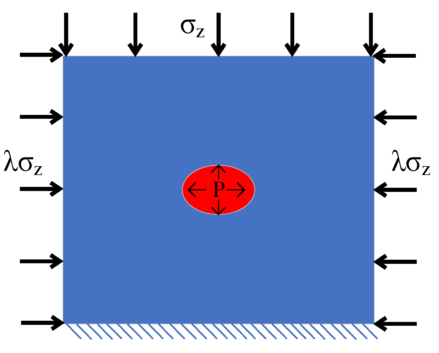
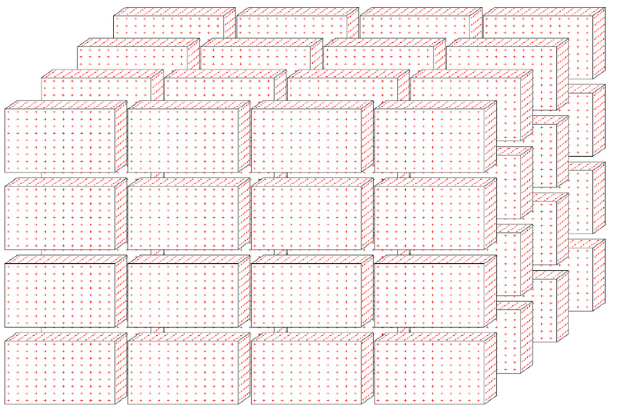
2.1.2. Setting of the Numerical Model

To investigate the evolutions of the initiation direction, initiation pressure, propagation pressure and propagation trend of cracks induced by CO2 in coal, a numerical analysis model with a single fracturing borehole was established. According to the construction of the coal mine fracturing site, it is somewhat simplified. The whole model with dimensions of 40 m × 30 m was partitioned into 400 × 300 elements. The coal seam with a thickness of 2 m was distributed evenly between the roof and floor, in which the thicknesses of the roof and floor strata were 3 m. The fracturing borehole with a designed radius of 0.094 m was located in the center of the model, in which a fracturing device was placed thereinto. The model is shown in Figure 1.

2.1.3. Scheme Design and Material Parameters

According to the mining situation of the coal seam on site, the vertical stress σz is determined as 10 MPa and further conditions at different lateral pressure coefficients are analyzed to attain the exact results of numerical analysis and ensure the stability of the model calculation. Coal and rock are elastic-brittle materials, the tensile strength of which is much lower than their compressive strength. Without the influence of the other excavation activities, the bottom boundary is fixed and the two sides are subjected to a lateral horizontal confinement of 8 MPa. During the model calculation, the initial pressure is set as 7.39 MPa and the pressurization is stopped after the crack initiates. Because the pressure at the critical point of the gaseous, liquid and supercritical states of carbon dioxide is 7.39 MPa and the temperature is 31.06 °C, carbon dioxide changes from liquid to gas when the pressure increases. In these conditions, the dynamic changes in the stress and displacement and crack propagation in coal around the fracturing borehole during the LCPCF are simulated. When selecting the model parameters, the compressive strength of coal seams is calculated based on the Protodyakonov coefficient of the 2131 transportation roadway in the mine. Since the macroscopic strength of coal is approximately 1.1 MPa, the mean of the mesoscopic strengths of coal during the simulation is 6 MPa. The other parameters, as shown in Table 1, are selected by comprehensively considering the geological conditions in the mine.

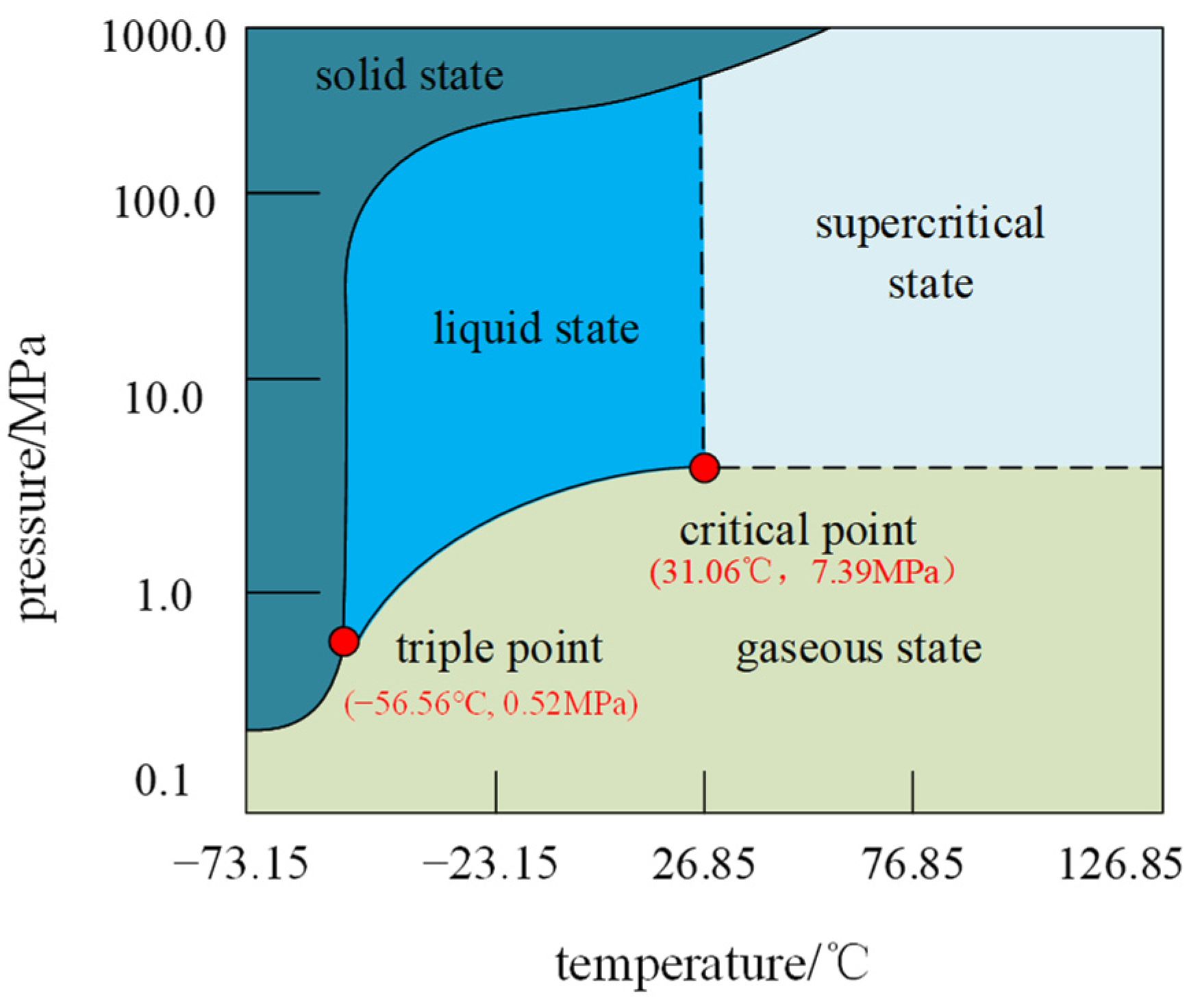
2.2. Thermodynamic Analysis of CO2 Phase Change

The transition between the gaseous, liquid, and solid states of matter is called the phase change, which is controlled by the changes in the pressure and temperature and belongs to physical change. Pressure and temperature directly influence the phase state and physical characteristics of CO2. The combination of different temperatures and pressures leads to the formation of gaseous, liquid, solid, and supercritical CO2. The supercritical state appears above the critical point. Figure 2 shows the relationship of the CO2 state with the pressure and temperature [26]. The critical pressure and temperature of the gaseous, liquid, and supercritical states are 7.39 MPa and 31.06 °C, respectively. According to the working mechanism of LCPCF, it can be seen that the fracturing technology belongs to a physical change process from liquid to gaseous CO2. The energy is mainly derived from physical explosive energy.

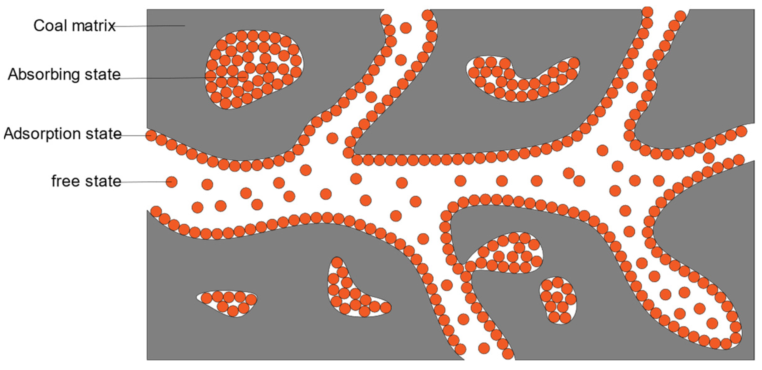
2.3. Mechanical Properties and Permeability Characteristics of Coal

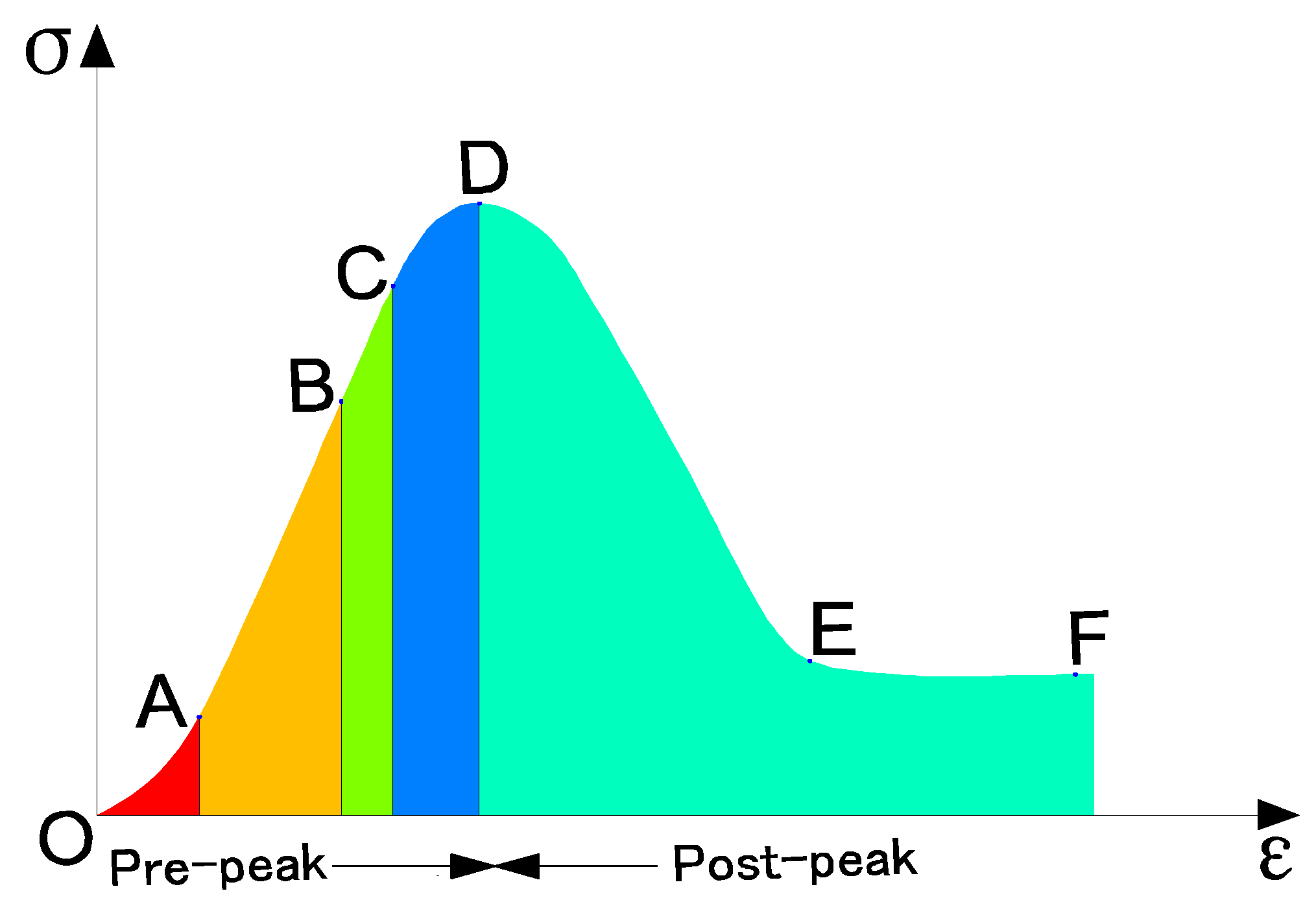
2.3.1. Mechanical Deformation Characteristics of Coal

Coal is a sedimentary rock, is a special rock material [64,65,66], and has the general characteristics of rock, but due to the different composition of the material, coal has special characteristics [67,68,69]. In particular, coal is a porous medium containing a large amount of gas, different from the dense and single nature of general rock, and the mechanical strength of coal refers to the ability of coal to resist damage when subjected to external forces, which is one of its mechanical properties. The strength of coal varies due to the different nature of external loads on the coal body, such as unidirectional force or multidirectional force, tensile or compression, and the different length of time of external loads. The stronger the coal is, the more difficult it will be for CO2 fracturing to take place. The coal body is a brittle material, and the expansion of CO2 cracking is often produced under tensile stress. When coal adsorbs gas, expansion deformation occurs, and its deformation obeys the Langermuir equation, which is as follows:
S = U V P 1 + V P
where, S is the amount of expansion deformation; P is the adsorption gas pressure; U is the amount of maximum expansion deformation; and V represents relationship between the gas pressure and expansion deformation.
When the coal body desorbs the gas, contraction deformation occurs, and the deformation obeys the exponential equation, i.e., Equation (3).
S = ae bp
where S is the contraction deformation of the coal body; p is the atmospheric pressure (MPa); and a and b are the adsorption constants.
The formation of coal is subject to the action of many factors, which creates coal with multiple fractures and complex mechanical properties, and the physical and mechanical properties of coal usually exhibit the specimen size effect. Previous studies have shown that the full stress–strain relationship is obtained for the deformation process of coal under the action of external forces, as shown in Figure 2.
After the peak D is reached, the coal body will be damaged to a certain extent, and the internal cracks will be further developed, and even the rupture surface (such as section DE in Figure 3) and slip surface will appear. Before the coal body reaches the peak D, the process of change in the internal structure of the coal body corresponding to each curve is as follows: the OA section is the coal internal primary fracture closure, and the deformation curve shows the upward concave trend; the AB section has a small amount of micro-fractures inside the coal, and the deformation curve is in a nearly straight state; the BC section has the further development of cracks, the coal body produces partial plastic deformation, and the curve shows a concave state; and the CD section has newly generated fractures along a certain direction The newly generated cracks in the CD section penetrate each other along a certain direction, forming through rupture cracks, and the curve presents a downward concave state. Macro rupture occurs when the stress reaches and exceeds the compressive strength of the coal body.

2.3.2. Characteristics of Coal Permeability Variation

The permeability of the coal rock body is a complex issue, and the seepage of the coal rock body can be broadly classified into three kinds: quasi-uniform medium seepage, fracture medium seepage and karst medium seepage. There are many factors affecting the permeability characteristics of coal seams, including particle size and gradation, pore structure, mineral composition, porosity, temperature, pressure, etc. The coal seam is a typical dual medium consisting of a matrix micropore system with 70–90% methane adsorption and a cut fracture system, as shown in Figure 4.
Because of the existence of the pore system, the internal stress of gas-bearing coal can be decomposed into the interaction force between the coal matrix and the compression force of gas in the pore, so when the physical deformation or physical damage of gas-bearing coal occurs, it is bound to be restrained by the effective stress of gas in the pore, that is, the mechanical effect of gas on coal. Because the gas not only attaches to the surface of the coal matrix but also partly absorb deep inside the matrix, become part of the matrix, gas in the coal seam fissure network flow forms a kind of seepage movement. When the pressure of gas in the block of coal is higher than the external pressure, the absorption (dissolved) in the block of coal will become desorption, and from the surface of the block of coal and out of the pore a fissure network in the flow and transport state is formed. Figure 5 shows the transport pattern of coal seam gas.
The gas inventory attached to the surface is not constant, and some external factors may shift the equilibrium between gas adsorption and resolution, resulting in different surface inventories, all of which have certain effects on the intrinsic side of the coal, i.e., the non-mechanical effects of gas. The adsorption and resolution of gas and coal at a certain temperature is closely related to the gas pressure, so the change in gas pressure in the tiny pores must cause a chemical shift in the reversible equilibrium equation of gas resolution and adsorption, and thus the physical and mechanical properties of gas-bearing coal are changed accordingly.

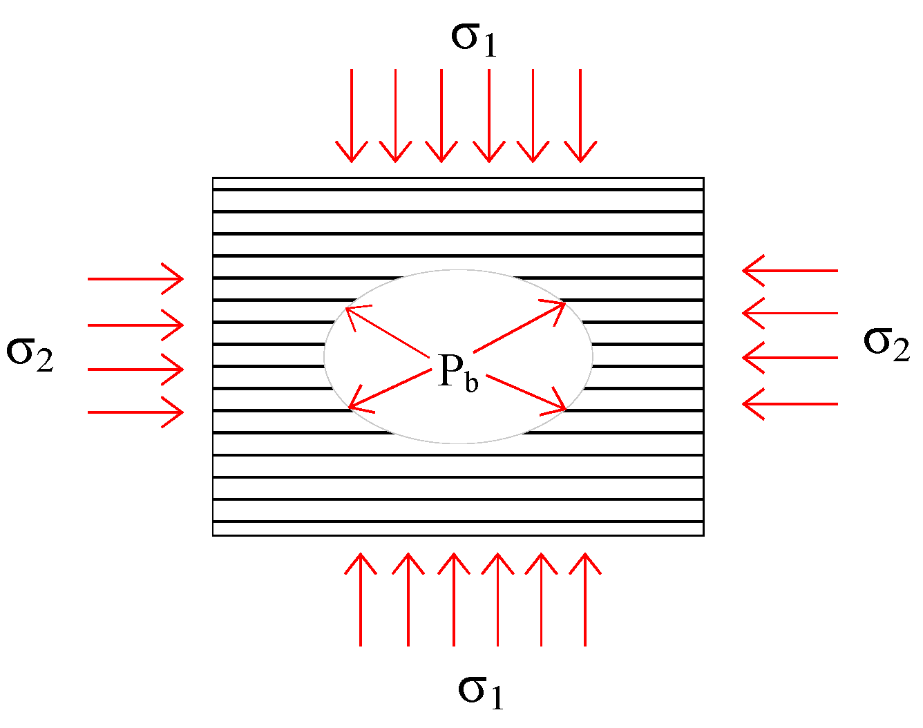
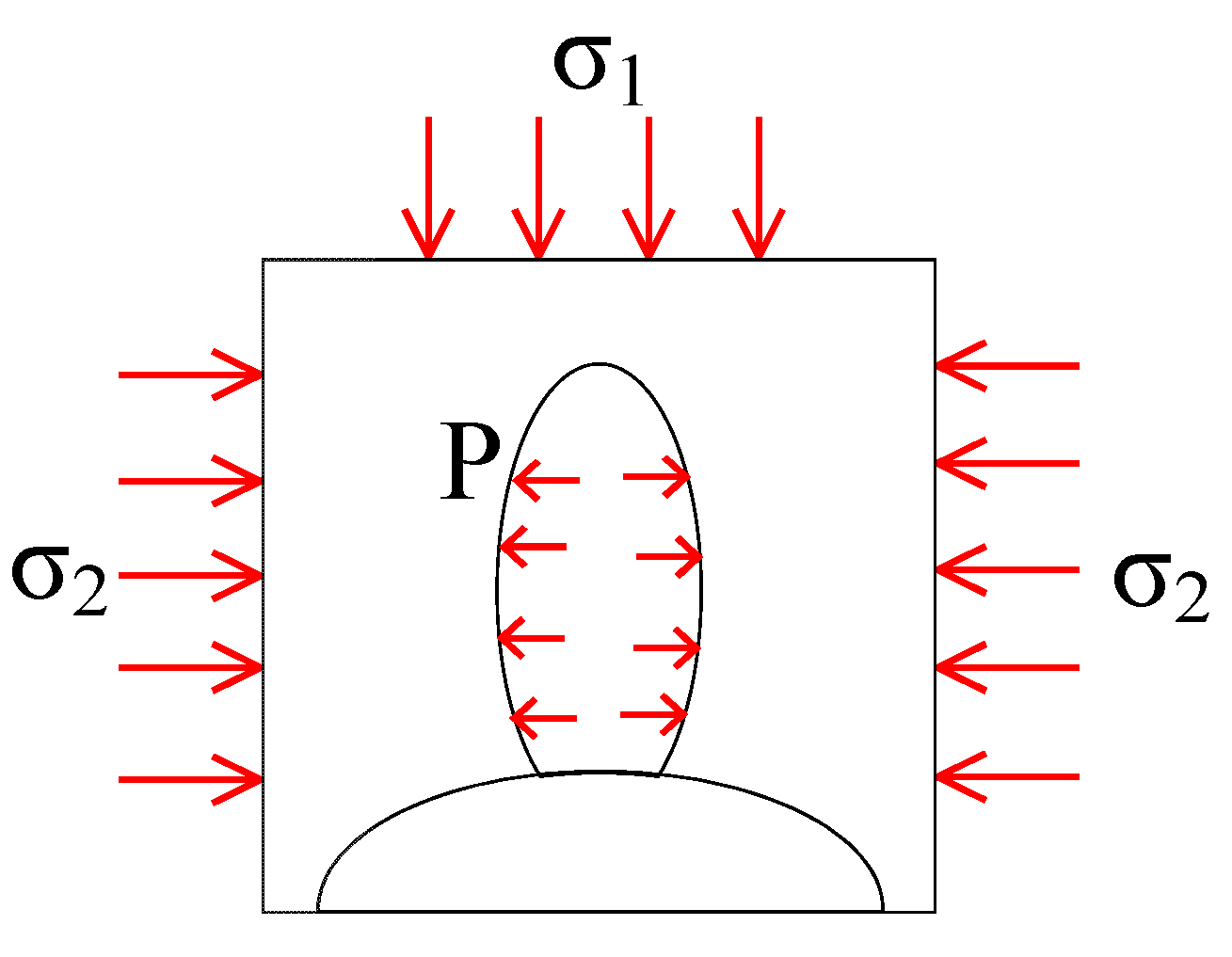
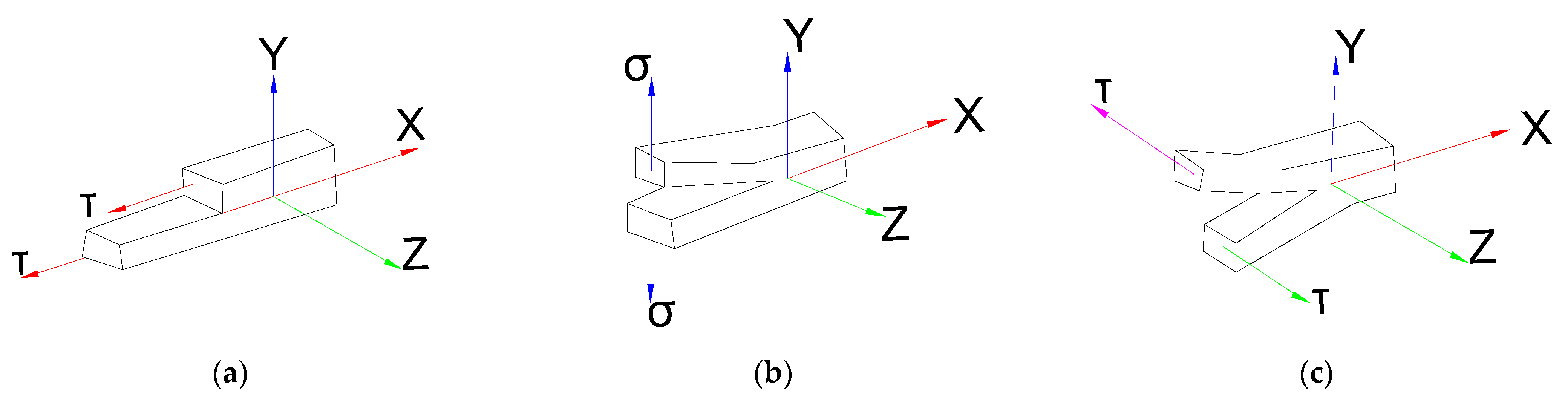
2.4. Mechanical Model and Mechanical Properties of Fracture Development

When performing the LCPCF, coal is subjected to compression-shear failure. The structural fracture of coal in the process is attributed to the tensile effect of high-pressure waves around the borehole, which leads to the generation of fractures and provides support for these fractures; afterwards, the crack tip continues to open under tension, propagate and extend and also coalesces and interacts with adjacent fractures. According to the technical characteristics of LCPCF underground, a small square coal block is selected in the vicinity of the borehole. A model is established in Figure 6, in which σ1, σ2, and Pb separately refer to the stress on the overlying strata, the lateral stress on two sides of the coal and the pressure of high-pressure waves on the internal surface of the fracturing borehole.
It is assumed that coal is linear-elastic, homogeneous, and isotropic, satisfying the equilibrium equation as follows:
σ r = 1 2 σ 1 + σ 2 1 a 2 r 2 + p b a 2 r 2 + 1 2 σ 1 σ 2 1 4 a 2 r 2 + 3 a 4 r 4 cos 2 θ σ θ = 1 2 σ 1 σ 2 1 + a 2 r 2 + p b a 2 r 2 1 2 σ 1 σ 2 1 + 3 a 4 r 4 cos 2 θ
where, σ 1 , σ 2 , σ r and σ θ refer to the vertical principal stress (MPa), horizontal lateral stress (MPa), radial stress (MPa) and tangential stress (MPa) on coal, respectively; a , r , P b and θ denote the length (m) from coal to the center of the borehole, the radius (m) of the fracturing borehole, the fracturing pressure (MPa) and the radial angle (°), respectively.
The radial stress and tangential stress on the internal surface of the fracturing borehole separately appear as the compressive stress and tensile stress under the synergistic effect of geostress and high-pressure waves. The borehole wall is subjected to compression-shear failure if the compressive stress is higher than the compressive strength of the coal; the borehole wall is subjected to tensile failure if the tensile stress is higher than the tensile strength of the coal. In these conditions, the initial pressure triggering the initiation of fractures on the borehole wall is transformed into P b .
At r = a on the borehole wall, it can be seen that
σ r = P b σ θ = σ 1 + σ 2 + p b 2 σ 1 σ 2 cos 2 θ
At θ = 0 , σ θ reaches the minimum (a positive along the compressive direction and a negative along the tensile direction), that is,
σ r = P b σ θ = 3 σ 2 σ 1 P b
At P b > 3 σ 2 σ 1 , the tensile stress is first found on the internal surface of the borehole and therefore the tangential tensile failure probably appears. At P b = 0, no tensile stress occurs within the borehole under 3 σ 2 σ 1 . Failure occurs once the tensile stress appears in coal (rock) according to the tension-free criterion. Assuming that the tensile stress is σ θ T 0 (tensile strength),
P b = 3 σ 2 σ 1 + T 0
When the pressure P 0 of high-pressure waves in pores occurs in coal (rock),
P b = 3 σ 2 σ 1 + T 0 + P 0
At θ = 0 or π, the stresses on the two ends around the borehole are at the minimum, that is, the tensile stress is at the maximum; at θ = π/2 or 3π/2, the stress on the tip around the borehole is the at maximum, that is, the compressive stress is at the maximum.
Since the compressive strength is far greater than the tensile strength of coal, cracks first initiate at the weakest parts (that is, the upper and lower ends) of coal. In this case, high-pressure waves propagate into and further split the fractures under the tip effect, which rules out the possibility that the left and right ends of coal are damaged by the compressive stress. As coal belongs to a double medium with the significant development of pores and fractures, new fractures are generated based on one or multiple fractures during the construction of boreholes; moreover, high-pressure waves propagating to the boreholes quickly enter and occupy the fractures, as shown in Figure 7. The waves filling in the fractures appear as a wedge shape, showing the stress concentration at the tip. Hence, the generation of the wedge effect is the main factor inducing coal fracture during CO2 fracturing. According to the inclination of cracks, the cracks formed in coal seams under CO2 fracturing include vertical and horizontal cracks, and also involve oblique and compound cracks. Figure 8 shows the propagation modes of some cracks formed by CO2 fracturing.

3. Results and Analysis

3.1. Analysis on Pressure on the Coal to Be Fractured

To explore the propagation of pressure in coal during the LCPCF, the nephograms (Figure 9) showing the pore pressure during the LCPCF are derived based on the analysis on the fracturing process, with pressure increased by steps from an initial pressure of 7.39 MPa.
It can be seen from Figure 9 that the fractures in coal initiate, propagate and coalesce to form macrofractures with increasing pressure during the LCPCF. As shown in Figure 9a,b, microfractures start to occur in the vicinity of the borehole when high-pressure gas flows into coal. In this case, the fractures do not present an obvious dominant direction. As shown in Figure 9c,d, the shear stress and principal stress in the vicinity of the borehole become negatives at first and they are more negative with the increase in the pressure of high-pressure waves. Furthermore, significant macrofractures start to appear around the borehole; afterwards, numerous microfractures are rapidly generated and they constantly propagate towards the deep part of coal in a fan shape along the direction of coal seams. The microfractures constantly coalesce to eventually form a macrofracture in the coal. With the further increase in the pressure of high-pressure waves, the fractures in coal coalesce and macrofractures are gradually developed until coal failure. The reason for these phenomena may be that the presence of liquid CO2 gasification heat absorption and high pressure causes a large number of artificial microfractures in the coal body, and the areas of stress concentration move deeper into the coal body, causing a longer pressure relief zone in the front.

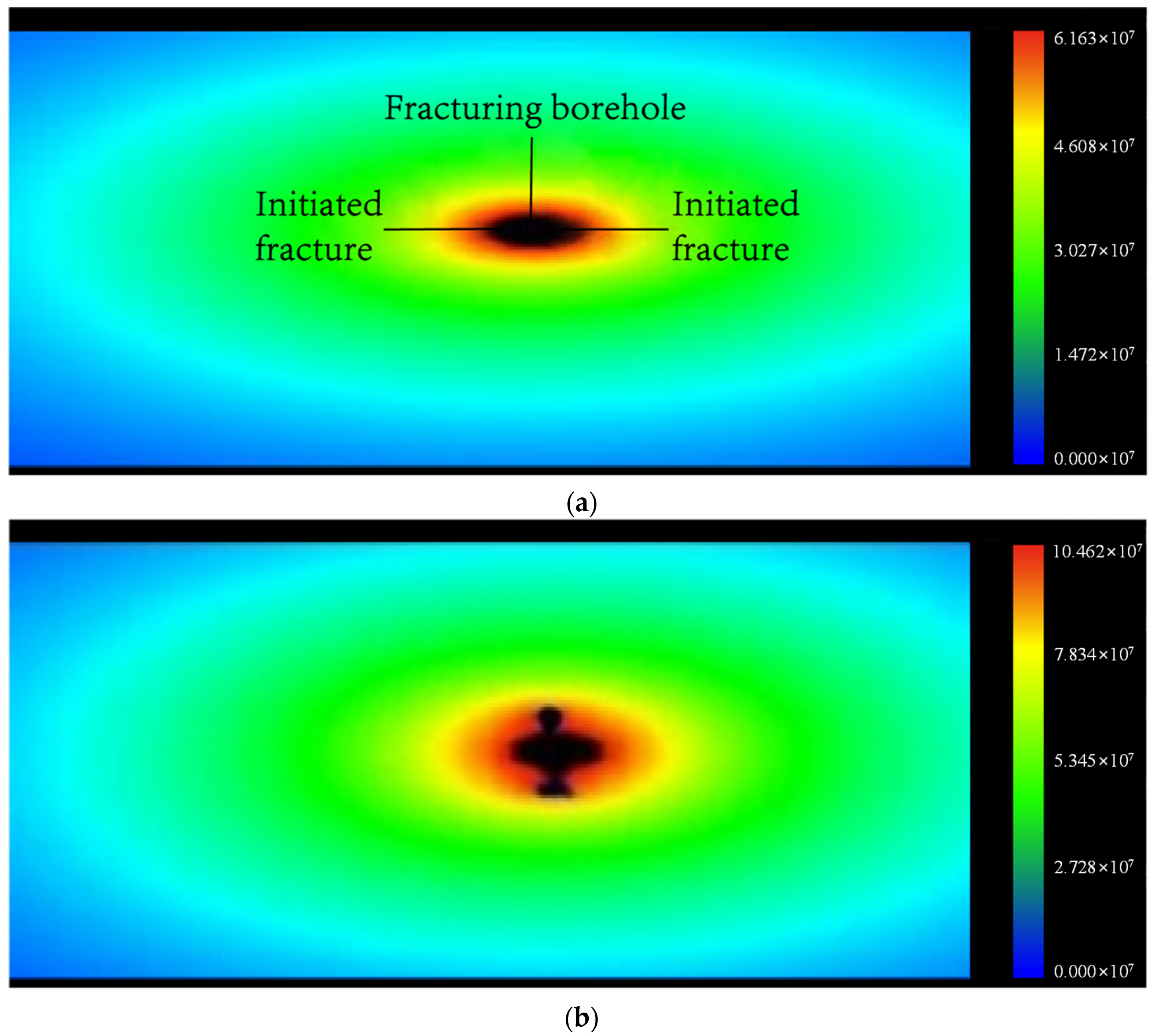
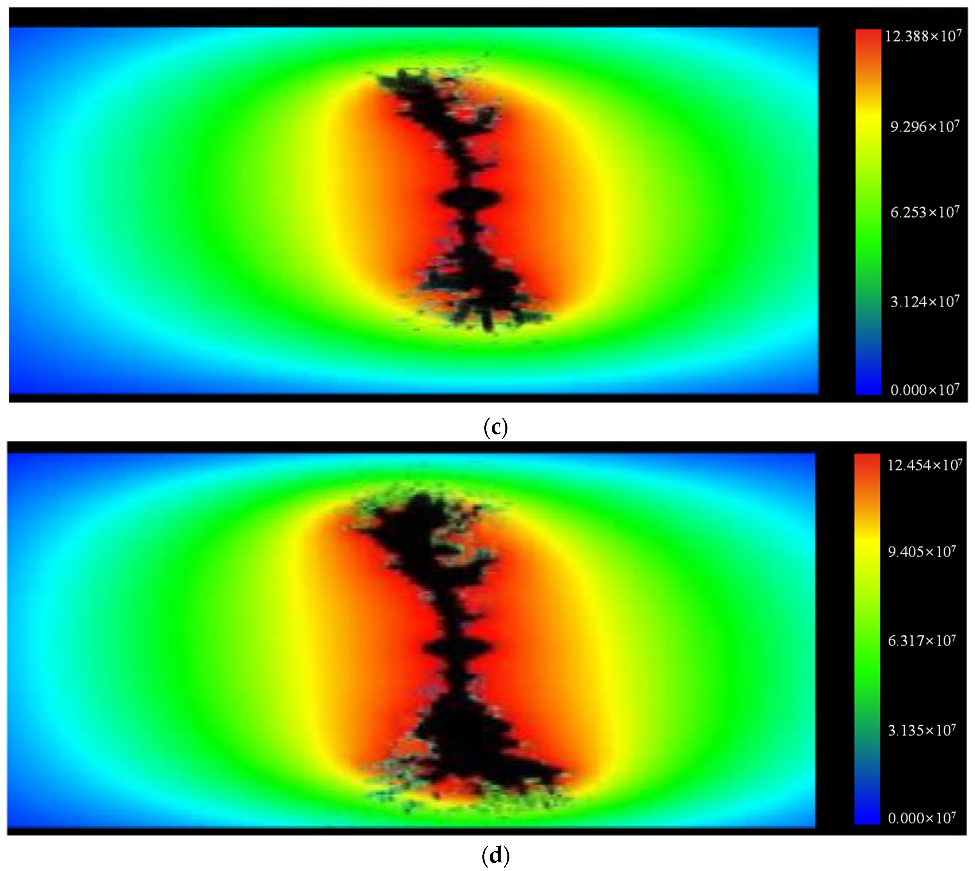
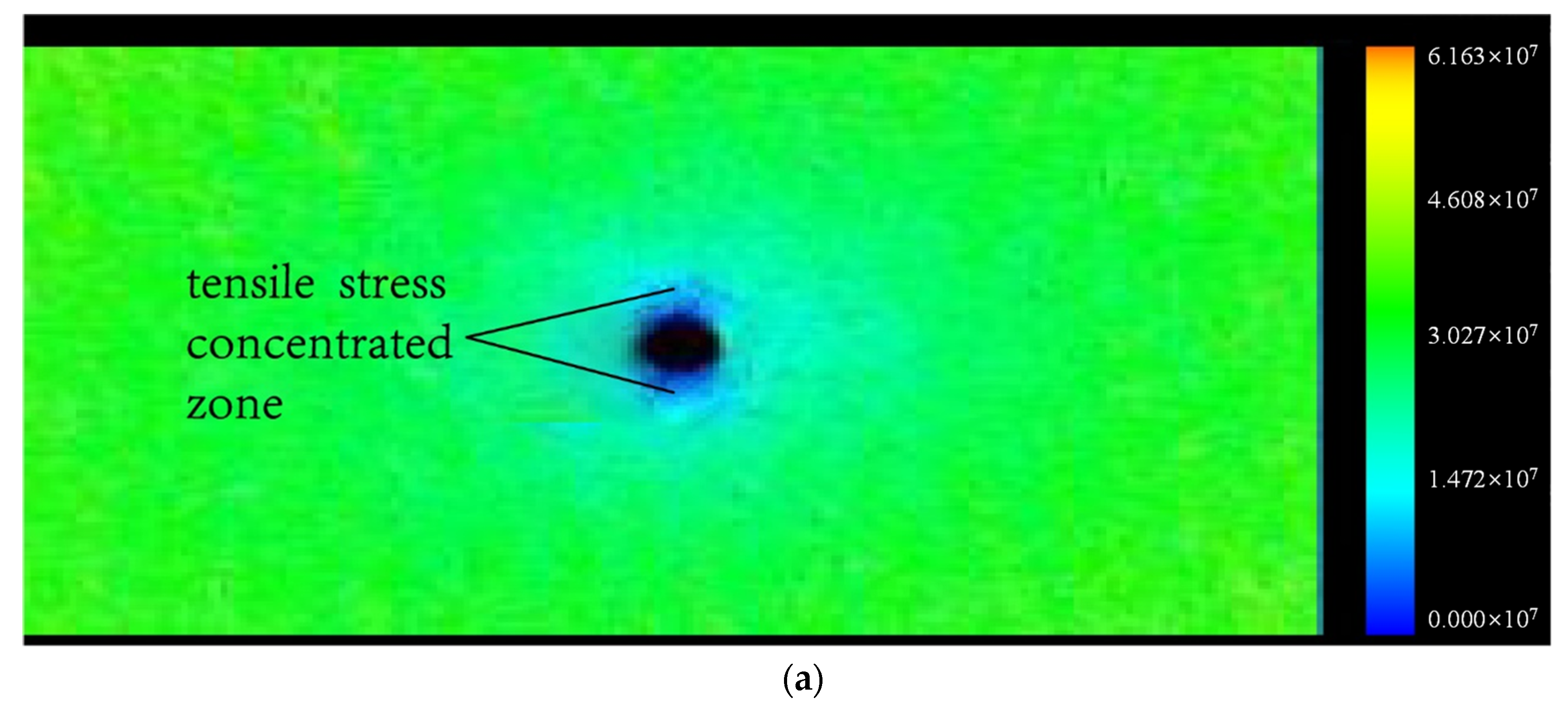
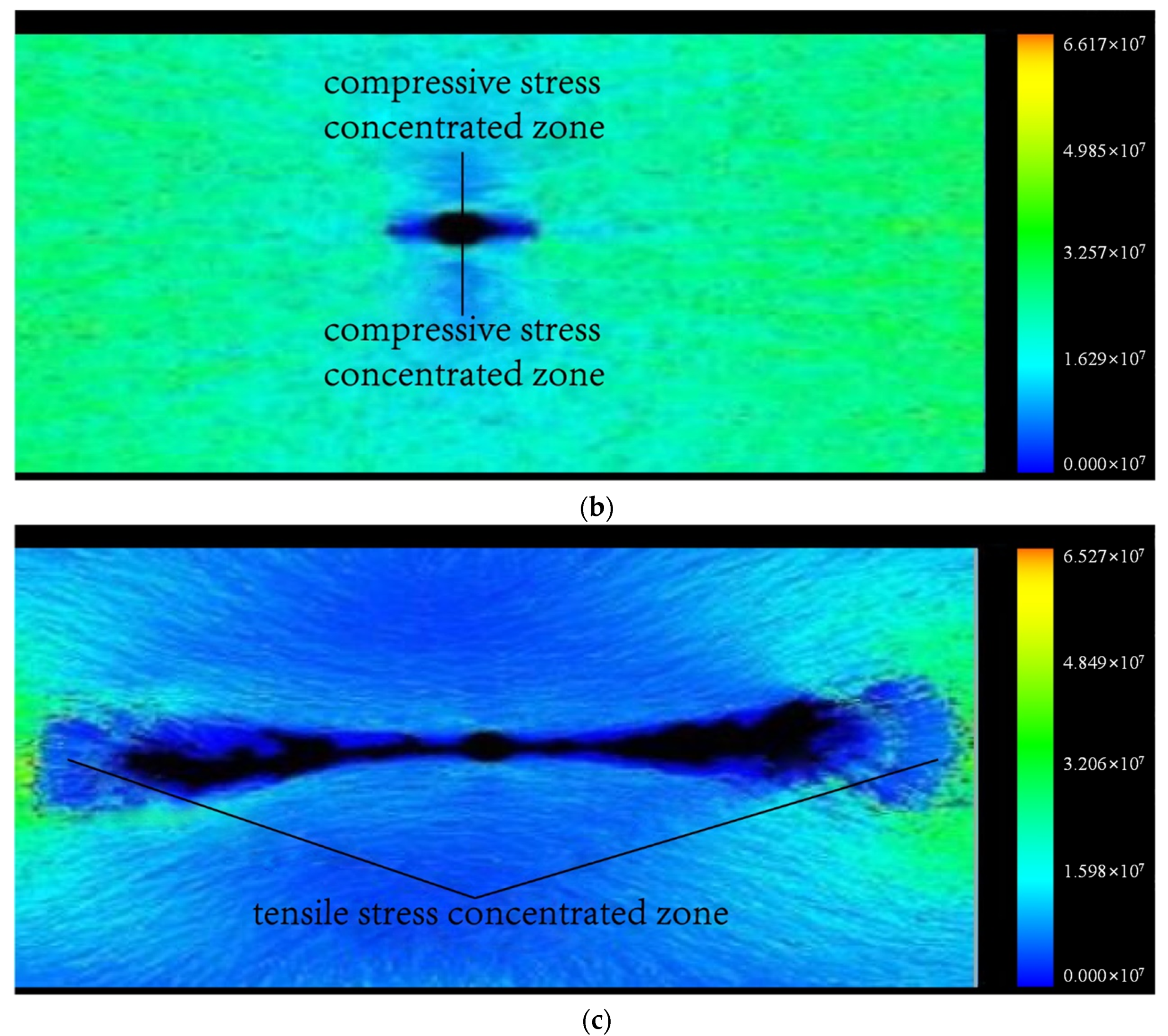
3.2. Analysis on the Stress on Coal

Figure 10 displays the crack propagation and distribution of shear stress on coal during the LCPCF.
It can be seen from Figure 10 that the stress is incompletely symmetrically distributed in coal centered on the fracturing borehole during the fracture development. As shown in Figure 10a,b, the shear stress concentrates in the vicinity of the crack tip and is distributed in a strip shape. As shown in Figure 10c. As the failure continues and the fractures propagate into the deep coal, the shear stress concentrated zone shifts to the deep coal and the shear stress in the damage zone is effectively released. The tensile stress concentrated zones are present in coal around the fracturing borehole, distributed in blocks. In the accumulation stage of the tensile stress, the stress state of surrounding rocks of the fracturing borehole varies and also the tensile stress concentrated zone shifts to the deep part as the fractures propagate to deep coal. In the fracture initiation and propagation stage, the weak element of coal is damaged at first when the cumulative tensile stress on surrounding rocks of the fracturing borehole approximates to the tensile strength of coal. This phenomenon occurs also because of the presence of nonuniformity of coal and setting of heterogeneous parameters in the model. Furthermore, microfractures are formed and the tensile stress in the damage zone is released; however, the pressure-relief effect is inferior to that of the shear stress. In the fracture propagation and extension stage, microfractures gradually propagate, extend, interact and coalesce to form a major macrofracture, which stably propagates; moreover, the tensile stress concentrated zone always occurs at the crack tip and advances forwards with the crack propagation. It is also regarded as the power for stable extension and propagation of the macroscopic major crack. The major microfracture gradually increases and rapidly propagates along the direction of the coal seam at an obviously increasing rate. Finally, coal failure happens.

3.3. Analysis on the Displacement of Coal

When establishing the model, the horizonal position of the fracturing borehole in coal is selected as the monitoring line for the displacement change. Ten units represent 1 m and the trend of the displacement change at various points on the monitoring line conforms to the crack initiation and propagation process. Figure 11 shows the failure development of coal during the LCPCF.
As shown in Figure 11a, initially, the failure stochastically appears in coal around the fracturing borehole at first. As shown in Figure 11b,c, the failure gradually propagates from the borehole to the inner seam of the coal with increasing gas pressure and the damage zone is distributed in a fan shape. As shown in Figure 11d, when the damage zone reaches the roof and floor of the coal seam, the failure continues to propagate towards the deep coal along the roof and floor, owing to these areas having far higher strength than the coal. Since the damage zone is distributed in a fan shape, the tensile failure is mainly found in coal during the development of fractures. At first, coal around the fracturing borehole is damaged and displaced. The coal in the vicinity of fractures is displaced towards the two sides under the effect of gas pressure. The displacement rapidly reduces from the borehole to the deep coal until coal is not displaced. This is because fractures are mainly generated in the vicinity of the fracturing borehole, and do not propagate towards deep coal. The displacement changes in various parts gradually stabilize as the failure process continues, and the position of displaced coal also gradually shifts to the deep part. The main reason is that the damage zone of coal is expanded and fractures propagate to deep coal. Additionally, this shows that the area of stress concentration moves deeper into the coal body after the LCPCF is adopted, causing a longer pressure relief zone in the front.

3.4. The Influence of the Lateral Pressure Coefficient on the Crack-Initiation Direction of Coal

To explore the evolution of cracks in coal during the LCPCF under different lateral pressure coefficients, λ, numerical simulation is carried out in these different conditions. On this basis, the crack-initiation direction of the initial failure of surrounding rocks of the fracturing borehole is attained. Figure 12 shows the crack-initiation directions under different lateral pressure coefficients. Although the crack-initiation pressures and calculation steps for crack initiation vary under different lateral pressure coefficients, the crack-initiation direction is regular. As shown in Figure 12a,b, at λ < 1 and λ = 1, the crack initiates basically perpendicularly in the coal around the fracturing borehole. As shown in Figure 12c, at λ > 1, the crack-initiation direction of coal around the borehole is basically horizontal.

4. Field Test

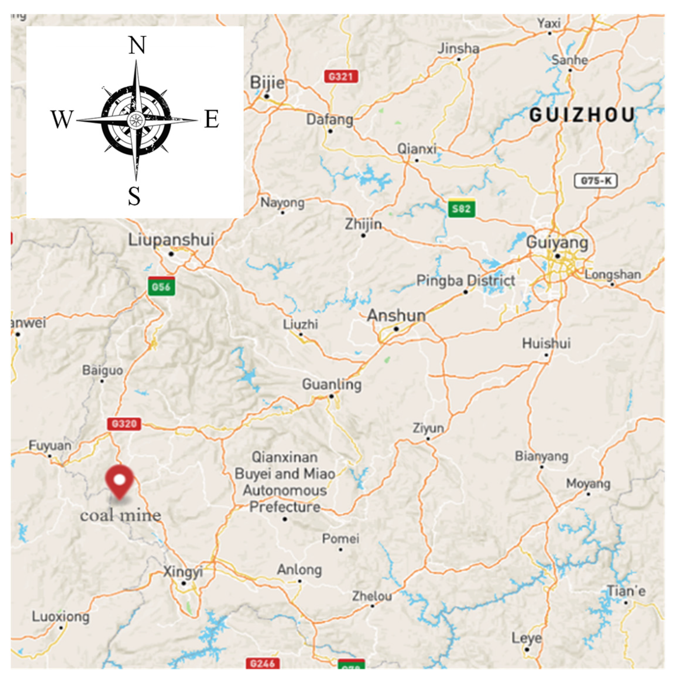
4.1. Overview of the Coal Mine

The Xiangshui Mine is located in the southern part of Panzhou, Guizhou Province, within the boundaries of Xiangshui Town, Dashan Town and Zhongyi Township. The location map is shown in Figure 13. In terms of the landform, the mine field is located high in the middle part, while it is low in the two wings. The mine field is located in the western end of the southeastern wing of the Pannan anticline. Longtan formation is the coal-bearing formation in the No. 1 mining area in the east, containing 20~40 (generally, 28) coal seams, showing a total thickness of 23.14~44.85 m, with an average thickness of 33.64 m and a coal bearing ratio of 13.3%. There are 13 mineable or locally mineable coal seams, with a total thickness of 13.79~36.32 m (23.60 m on average) and a coal bearing ratio of 9.4%. The 2131 transportation roadway was excavated from Y23 + 18 m along the direction of the 3# coal seam, with the azimuth of 71°. The 3# coal seam exhibits the dip of about 15° and a thickness of 2.4~3.4 m, with a maximum gas pressure of 1.65 MPa, maximum initial gas diffusion velocity of 18.24 mmHg and minimum Protodyakonov coefficient of 0.33.

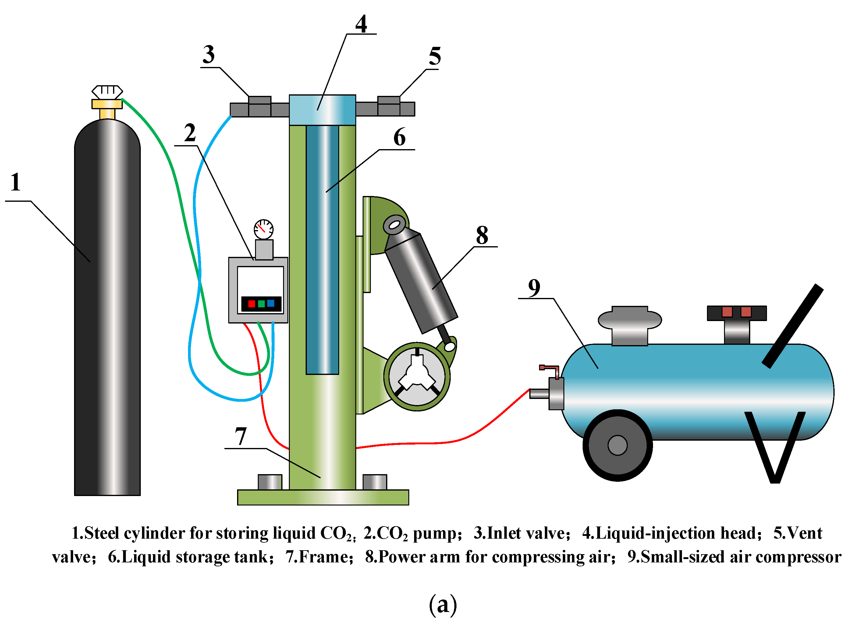
4.2. Technological Equipment for LCPCF

The whole set of the LCPCF system mainly consists of three subsystems, i.e., a liquid CO2 charging system, a liquid CO2 fracturing system, and a fracturing device pushing system, as shown in Figure 14. To increase the permeability of the coal seams through LCPCF, it is necessary to charge liquid CO2 into the fracturing device, and then safely and accurately send the charged fracturing device to the preset position of coal and rock to be fractured using the pushing system. Finally, the permeability of coal seams is increased by triggering the heating device in the fracturing system through electrical signals.

4.3. Test Schemes

The presplit boreholes are designed at a position 5 m in the rear of the borehole 7-1# in the scheme. According to the roadway distribution and existing gas drainage conditions in the working face of the 2131 transportation roadway, 15 presplit CO2 boreholes (also serving as boreholes for gas drainage after presplitting) are distributed in the left side. The spacing between every two boreholes is set as 5 m, with a borehole size of 94 mm and borehole depth of 120 m. Figure 15 shows the distribution of the boreholes.
Five boreholes are distributed in the lower sidewalls of the 2131 transportation roadway. Boreholes 1# and 2# are not used for increasing the permeability through presplitting and are instead used for observing the original permeability coefficient of the coal seam and the natural attenuation coefficient of gas flow therein. Boreholes 4-2#, 5-2# and 6-2# are used for increasing the permeability through presplitting and are also applied to measure the permeability coefficient and the natural attenuation coefficient of gas flow after completing presplitting. A comparison is made between the presplit boreholes and non-presplit boreholes in terms of the permeability coefficient and natural attenuation coefficient of gas flow.
After draining gas from the non-presplit boreholes (1#, 2#, 3#, 4#, 5-1#, 6# and 7-1#), the concentration and pure amount of gas extracted are observed every day. The observed results are taken as the original concentration and pure amount of gas drainage before increasing the permeability through presplitting. After presplitting the boreholes and normally draining gas from the boreholes, the concentration and pure amount of gas extracted from the coal seam are observed every day. The observed values are taken as the concentration and pure amount of gas extracted from the presplit boreholes. A comparison is made between the presplit and non-presplit boreholes in terms of the concentration and pure amount of gas extracted.

4.4. Observation of the Test Effects

4.4.1. Comparison of Permeability Coefficients

Five boreholes are distributed in the lower sidewalls of the 2131 transportation roadway. Boreholes 1# and 2# are used to measure the permeability coefficient of the coal seam in the non-presplit zone while boreholes 4-2#, 5-2# and 6-2# are applied to measure the permeability coefficient of the coal seam after increasing the permeability through presplitting. After sealing various measurement boreholes, the natural gas flows in the boreholes are measured, as shown in Table 2.
Table 3 shows the permeability coefficients of the coal seam from various boreholes calculated according to the formula for the permeability coefficient.
As shown in Table 3, the gas permeability coefficient λ of the coal seam before increasing the permeability through presplitting equals 0.7228~0.9129 m2/MPa2·d while it is 2.3710~2.8924 m2/MPa2·d thereafter. The latter is 2.60~3.97 times larger than the former, which implies that the permeability of coal seams is greatly improved.

4.4.2. Comparison of the Natural Attenuation Coefficient of Gas Flows

The natural attenuation coefficient of gas flows in the boreholes can be taken as a factor for evaluating the difficulty of gas drainage in coal seams to be mined. According to the measurement results of the natural gas flows, the attenuation coefficient β is calculated through regression:
q t = q 0 · e β t
where, q 0 , q t and β refer to the initial gas flow (m3/min), the gas flow (m3/min) after a time period of t and the attenuation coefficient (d−1) of gas, respectively.
The natural emission of gas from various boreholes is fitted according to the measured natural gas flows in the boreholes, as shown in Figure 16.
It can be seen from Table 4 that the attenuation coefficients of the natural gas flow from the boreholes before and after increasing the permeability through LCPCF are β = 0.33027~0.40624 d−1 and β = 0.24273~0.2592 d−1, respectively. That is, the attenuation intensity of the amount of gas emission from the boreholes after increasing the permeability through presplitting declines by 1.3~1.7 times. It can be seen that the permeability-enhancing technology through LCPCF effectively improves the fracture structures of coal in the presplit zone and makes gas easier to be desorbed and discharged, thus realizing the sustainability of gas drainage.

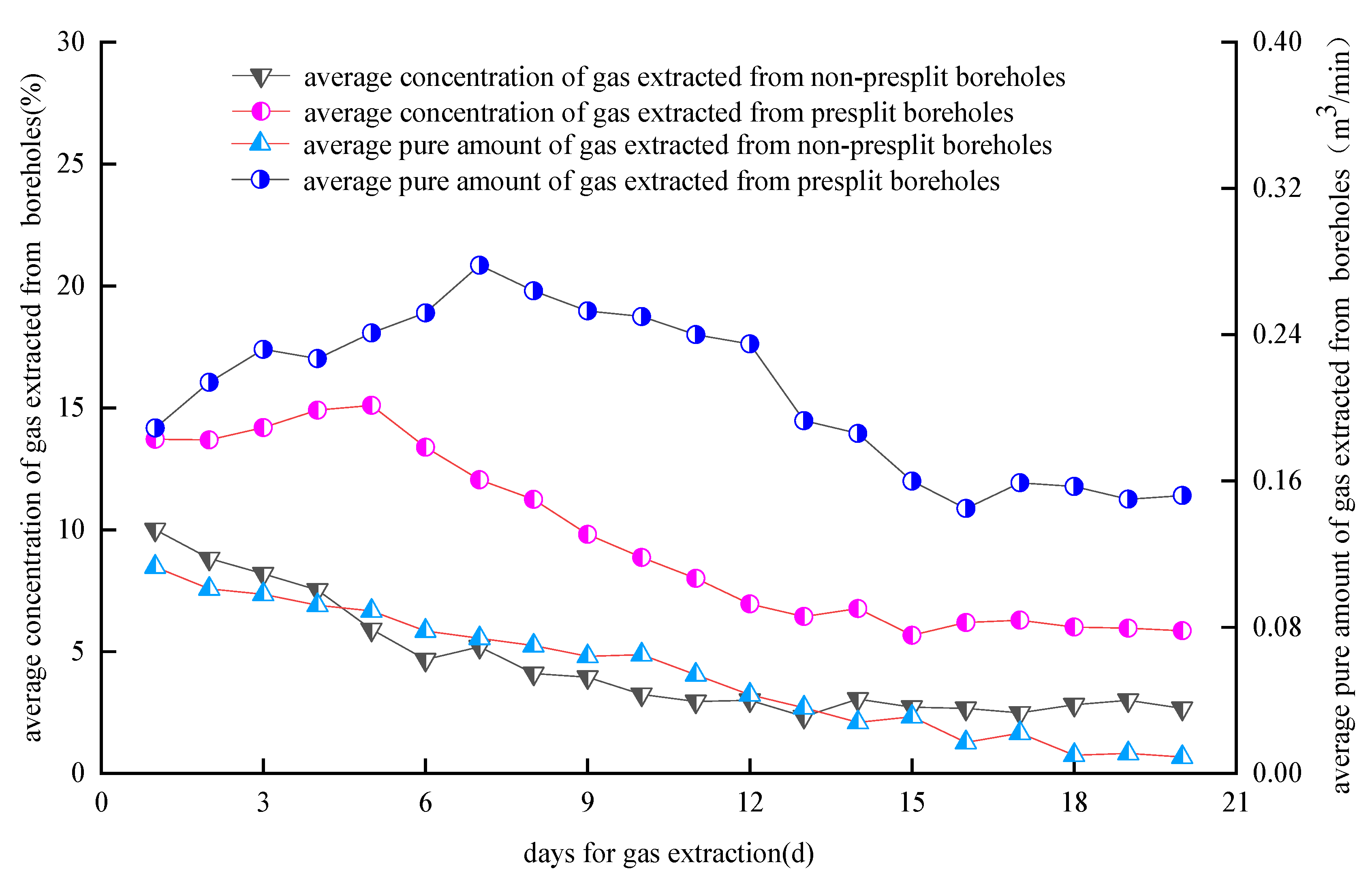
4.4.3. Comparison of the Concentration and Pure Amount of Gas Extracted from the Boreholes

After sealing and draining gas from the boreholes, the concentration and pure amount of gas extracted are measured by applying a CJZ7 gas extraction system measuring instrument for the comprehensive parameters of gas drainage [70]. The CJZ7 gas extraction system measuring instrument is an intrinsically safe instrument for measuring the performance of a gas extraction system. It is specifically used to measure the methane concentration, negative pressure of the pipeline, gas temperature, and other parameters of gas pumping in the pump and pipeline, and it can obtain the parameters related to the gas extraction system such as the gas mixed flow rate and pure flow rate according to the measured data and the parameters input by users. In addition, a comparative analysis is carried out on the observation data. The average concentrations and pure amounts of gas extracted within the same timeframe in the first 20 days from the presplit boreholes and non-presplit boreholes (1#~7-1#) are compared, as shown in Figure 17.
As shown in Figure 17, the average concentration of gas extracted from the non-presplit boreholes is 4.47% within 20 days and the concentration is maintained at approximately 2.6% after 10 d; the average concentration of gas drainage from the presplit boreholes is 9.56%, which is 2.14 times higher than that from the non-presplit boreholes. Moreover, the concentration of gas drainage gradually increases in the early period and finally stabilizes at approximately 5.9%. The pure amount of gas extracted from the non-presplit boreholes constantly attenuates, with a maximum of only 0.113 m3/min, and it gradually stabilizes at approximately 0.01 m3/min after gas drainage for 16 d. After increasing the permeability through LCPCF, the pure amount of gas extracted from the boreholes significantly increases. After completing the presplitting, the pure amount of gas extracted gradually increases, reaching a maximum of 0.278 m3/min after 7 days, then starts to decrease and finally stabilizes at approximately 0.15 m3/min after 15 days. The average pure amount of gas extracted from the presplit boreholes is 3.78 times as much as that from the non-presplit boreholes. The use of LCPCF technology can significantly improve the gas extraction effect. This may be due to the reopening of filled or compacted fissures in the coal body during liquid CO2 gasification, which generates a large number of artificial microfissures, thus increasing the permeability of the coal body. At the same time, the stress concentration area moves deeper into the coal body, causing a longer pressure relief zone in the front and improving the gas extraction efficiency.
It is worth noting that in this paper, based on the CO2 phase change thermodynamics theory, a mechanical model was established to numerically simulate the CO2 fracture expansion law and the coal body displacement and stress change law, and to reveal the mechanism of LCPCF for coal seam unloading and increasing permeation. In addition, a field application test was conducted in the 2131 transport road of Xiangshui coal mine in Panzhou, Guizhou province, and the changes in the permeability coefficient, natural flow decay coefficient, gas extraction concentration and pure volume of extraction in the borehole before and after the permeability enhancement were discussed. Additionally, field results again validate the results obtained from numerical simulations. However, in this paper, we only consider the adsorption kinetics of CO2 and methane, and the effect of liquid CO2 on methane is considered. However, regarding the coupling effect of water, methane and CO2 on the gas extraction effect, this is a very valuable research question, which may be the direction of future research.

5. Conclusions

According to the mechanical analysis of crack initiation and propagation in coal, the pressure change characteristics, crack propagation, and displacement change of coal during the LCPCF were analyzed based on numerical simulation. Moreover, the effect of the field LCPCF test in terms of increasing the permeability was analyzed. The following conclusions are drawn:
(1)
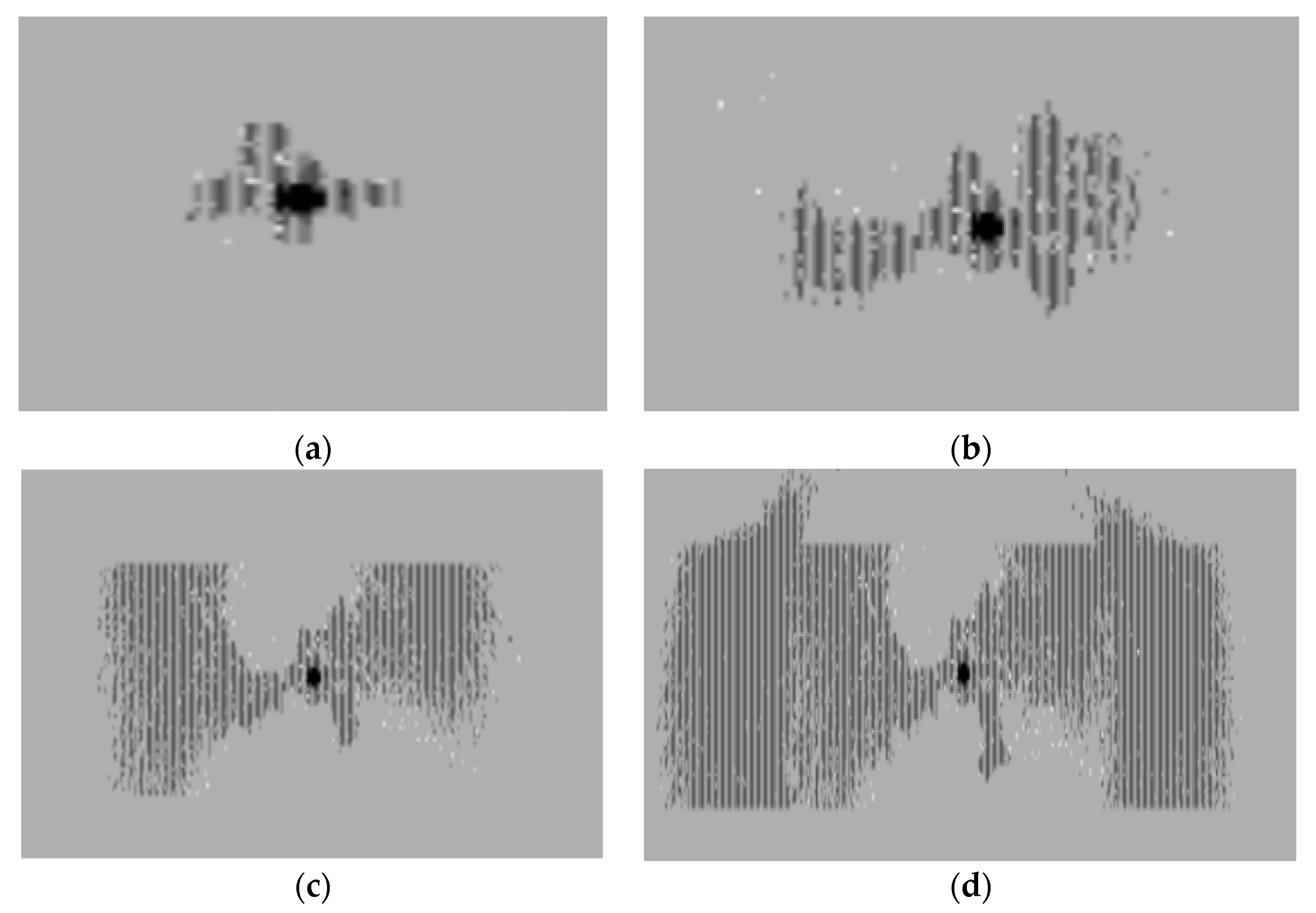
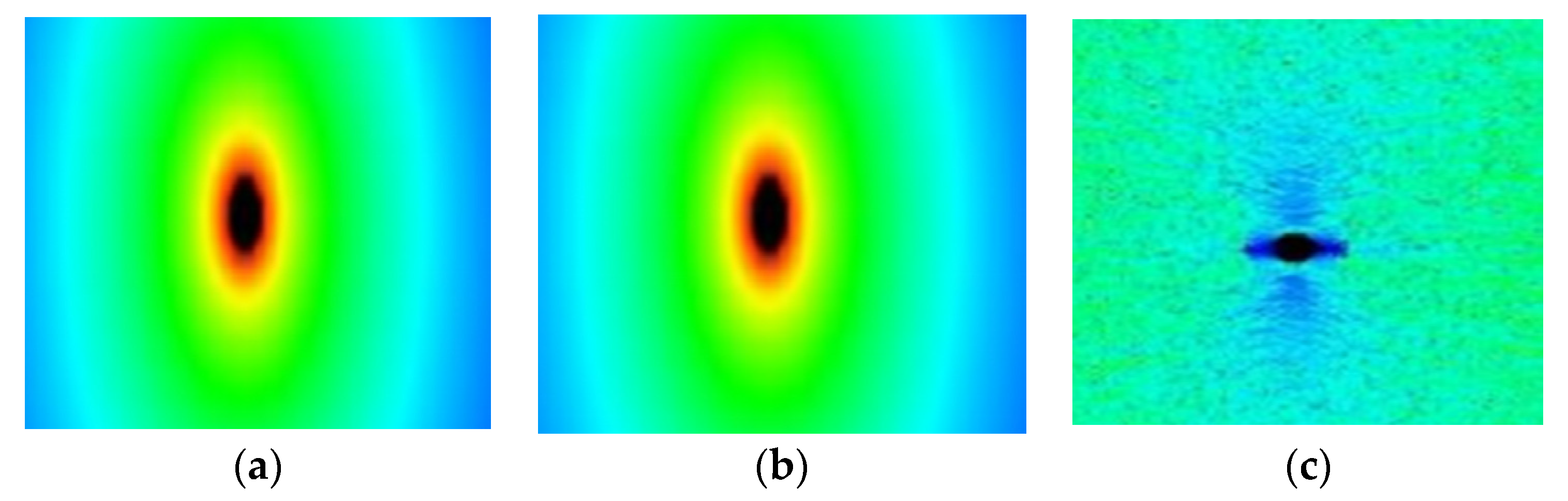
In the process of LCPCF, the crack-generation process changes with pressure as follows: microfractures–macrofractures–major macrofracture–macrofractures. The stress is incompletely symmetrically distributed in coal, being centered on the fracturing borehole during the development of fractures. Initially, the failure occurs stochastically in coal around the fracturing borehole; afterwards, the failure gradually propagates to the inner seam of coal with the increasing gas pressure.
(2)
The field test showed that the permeability coefficient of coal seams after increasing the permeability by LCPCF is 2.60~3.97 times that of coal seams without undergoing presplitting. In addition, the attenuation intensity of the natural gas emission from the presplit boreholes declines by 1.3~1.7 times. Within 20 days after gas drainage, the average concentration of gas extracted in the coal seam within the zone having undergone an increase in permeability through presplitting in the 2131 transportation roadway is 2.14 times greater than that of the zone without presplitting. The average pure amount of gas extracted within the zone having undergone an increase in permeability through presplitting is 3.78 times greater than that within the zone without presplitting.
(3)
Through the analysis of the fracture development and expansion pattern of fractured coal seams and the analysis of the actual effect of field experiments, it can be seen that CO2-LCPCF technology can improve the gas permeability of high gas and low permeability coal seams. This improves our understanding of CO2 fracturing in unconventional oil and gas extraction and can provide technical reference for coal mines with the same geological conditions.

Author Contributions

Z.J. and X.Q. conceived the experiment and analyzed the results; S.T., H.L., Y.G., X.F. and X.Y. coordinated the study and helped draft the manuscript. All authors have read and agreed to the published version of the manuscript.

Funding

The authors acknowledge financial support provided by the National Natural Science Foundation of China (52104079), and the Supported by Guizhou Provincial Science and Technology Projects ([2020]4Y050).

Data Availability Statement

The data presented in this study are available on request from the corresponding author.

Conflicts of Interest

The authors declare that there are no conflicts of interest regarding the publication of this article.

References

  1. Liang, Y.P.; Ran, Q.C.; Zou, Q.L.; Zhang, B.C.; Hong, Y. Experimental Study of Mechanical Behaviors and Failure Characteristics of Coal Under True Triaxial Cyclic Loading and Unloading and Stress Rotation. Nat. Resour. Res. 2022, 31, 971–991. [Google Scholar] [CrossRef]
  2. Zou, Q.L.; Zhang, T.C.; Ma, T.F.; Tian, S.X.; Jia, X.Q.; Jiang, Z.B. Effect of water-based SiO2 nanofluid on surface wettability of raw coal. Energy 2022, 254, 124228. [Google Scholar] [CrossRef]
  3. Zou, Q.L.; Liu, H.; Jiang, Z.B.; Wu, X. Gas flow laws in coal subjected to hydraulic slotting and a prediction model for its permeability-enhancing effect. Energy Source Part A 2021, 1–15. [Google Scholar] [CrossRef]
  4. Liu, S.M.; Li, X.L.; Wang, D.K.; Zhang, D.M. Experimental Study on Temperature Response of Different Ranks of Coal to Liquid Nitrogen Soaking. Nat. Resour. Res. 2021, 30, 1467–1480. [Google Scholar] [CrossRef]
  5. Deng, B.Z.; Zhang, D.M.; Chen, J.Q. Dilation behavior and acoustic emission response to water/CO2 injection-induced shear fracturing in coal seams. J. Nat. Gas Sci. Eng. 2021, 94, 104105. [Google Scholar] [CrossRef]
  6. Wei, G.M.; Wen, H.; Deng, J.; Ma, L.; Li, Z.B.; Lei, C.K.; Fan, S.X.; Liu, Y. Liquid CO2 injection to enhance coalbed methane recovery: An experiment and in-situ application test. Fuel 2021, 284, 119043. [Google Scholar] [CrossRef]
  7. Zou, Q.L.; Zhang, T.C.; Cheng, Z.H.; Jiang, Z.B.; Tian, S.X. A method for selection rationality evaluation of the first-mining seam in multi-seam mining. Geomech. Geophys. Geo Energy Geo Resour. 2022, 8, 17. [Google Scholar] [CrossRef]
  8. Tu, Q.Y.; Cheng, Y.P.; Xue, S.; Ren, T.; Cheng, X. Energy-limiting factor for coal and gas outburst occurrence in intact coal seam. Int. J. Min. Sci. Technol. 2021, 31, 729–742. [Google Scholar] [CrossRef]
  9. Gong, F.Q.; Wang, Y.L.; Wang, Z.G.; Pan, J.F.; Luo, S. A new criterion of coal burst proneness based on the residual elastic energy index. Int. J. Min. Sci. Technol. 2021, 31, 553–563. [Google Scholar] [CrossRef]
  10. Wang, H.D.; Cheng, Z.H.; Zou, Q.L.; Li, Z.H.; Sun, F.L.; Yang, H.W.; Lei, Y. Elimination of coal and gas outburst risk of an outburst-prone coal seam using controllable liquid CO2 phase transition fracturing. Fuel 2021, 284, 119091. [Google Scholar] [CrossRef]
  11. Wang, W.; Li, H.; Liu, Y.W.; Liu, M.J.; Wang, H.F.; Li, W. Addressing the gas emission problem of the world’s largest coal producer and consumer: Lessons from the Sihe Coalfield, China. Energy Rep. 2020, 6, 3264–3277. [Google Scholar] [CrossRef]
  12. Chen, S.B.; Zhang, C.; Li, X.Y.; Zhang, Y.K.; Wang, X.Q. Simulation of methane adsorption in diverse organic pores in shale reservoirs with multi-period geological evolution. Int. J. Coal Sci. Technol. 2021, 8, 844–855. [Google Scholar] [CrossRef]
  13. Gao, H.K.; Wang, Q.; Jiang, B.; Zhang, P.; Jiang, Z.H.; Wang, Y. Relationship between rock uniaxial compressive strength and digital core drilling parameters and its forecast method. Int. J. Coal Sci. Technol. 2021, 8, 605–613. [Google Scholar] [CrossRef]
  14. Li, C.X.; Guo, D.M.; Zhang, Y.T.; An, C. Compound-mode crack propagation law of PMMA semicircular-arch roadway specimens under impact loading. Int. J. Coal Sci. Technol. 2021, 8, 1302–1315. [Google Scholar] [CrossRef]
  15. Fan, S.X.; Zhang, D.; Wen, H.; Cheng, X.J.; Liu, X.R.; Yu, Z.J.; Hu, B.S. Enhancing coalbed methane recovery with liquid CO2 fracturing in underground coal mine: From experiment to field application. Fuel 2021, 290, 119793. [Google Scholar] [CrossRef]
  16. Cheng, X.J.; Wen, H.; Fan, S.X.; Chen, J.; Zhai, X.W.; Yu, Z.J.; Tong, X.Z.; Lei, C.X.; Xu, Y.H.; Cheng, B.K.; et al. Liquid CO2 high-pressure fracturing of coal seams and gas extraction engineering tests using crossing holes: A case study of Panji Coal Mine No. 3, Huainan, China. Int. J. Energy Res. 2021, 45, 4565–4580. [Google Scholar] [CrossRef]
  17. Qin, J.H.; Zheng, J.; Li, L. An analytical solution to estimate the settlement of tailings or backfill slurry by considering the sedimentation and consolidation. Int. J. Min. Sci. Technol. 2021, 31, 463–471. [Google Scholar] [CrossRef]
  18. Moore, T.A. Coalbed methane: A review. Int. J. Coal Geol. 2012, 101, 36–81. [Google Scholar] [CrossRef]
  19. Liu, J.S.; Chen, Z.W.; Elsworth, D.; Qu, H.Y.; Chen, D. Interactions of multiple processes during CBM extraction: A critical review. Int. J. Coal Geol. 2011, 87, 175–189. [Google Scholar] [CrossRef]
  20. Jangara, H.; Ozturk, C.A. Longwall top coal caving design for thick coal seam in very poor strength surrounding strata. Int. J. Coal Sci. Technol. 2021, 8, 641–658. [Google Scholar] [CrossRef]
  21. Wang, J.C.; Yang, S.L.; Wei, W.J.; Zhang, J.W.; Song, Z.Y. Drawing mechanisms for top coal in longwall top coal caving (LTCC): A review of two decades of literature. Int. J. Coal Sci. Technol. 2021, 8, 1171–1196. [Google Scholar] [CrossRef]
  22. Chen, H.D.; Wang, Z.F.; Chen, X.E.; Chen, X.J.; Wang, L.G. Increasing permeability of coal seams using the phase energy of liquid carbon dioxide. J. CO2 Util. 2017, 19, 112–119. [Google Scholar] [CrossRef]
  23. Liu, H.; Lan, Z.X.; Wang, S.L.; Xu, J.G.; Zhao, C.X. Hydraulic fracture initiation mechanism in the definite plane perforating technology of horizontal well. Pet. Explor. Dev. 2015, 42, 869–875. [Google Scholar] [CrossRef]
  24. Zou, Q.L.; Lin, B.Q. Fluid-Solid Coupling Characteristics of Gas-Bearing Coal Subjected to Hydraulic Slotting: An Experimental Investigation. Energy Fuel 2018, 32, 1047–1060. [Google Scholar] [CrossRef]
  25. Zhang, X.G.; Ranjith, P.G.; Li, D.Y.; Perera, M.S.A.; Ranathunga, A.S.; Zhang, B.N. CO2 enhanced flow characteristics of naturally-fractured bituminous coals with N-2 injection at different reservoir depths. J. CO2 Util. 2018, 28, 393–402. [Google Scholar] [CrossRef]
  26. Wang, T.; Hu, W.R.; Elsworth, D.; Zhou, W.; Zhou, W.B.; Zhao, X.Y.; Zhao, L.Z. The effect of natural fractures on hydraulic fracturing propagation in coal seams. J. Petrol Sci. Eng. 2017, 150, 180–190. [Google Scholar] [CrossRef]
  27. Zhu, W.C.; Gai, D.; Wei, C.H.; Li, S.G. High-pressure air blasting experiments on concrete and implications for enhanced coal gas drainage. J. Nat. Gas Sci. Eng. 2016, 36, 1253–1263. [Google Scholar] [CrossRef] [Green Version]
  28. Yan, F.Z.; Lin, B.Q.; Zhu, C.J.; Shen, C.M.; Zou, Q.L.; Guo, C.; Liu, T. A novel ECBM extraction technology based on the integration of hydraulic slotting and hydraulic fracturing. J. Nat. Gas Sci. Eng. 2015, 22, 571–579. [Google Scholar] [CrossRef]
  29. Niu, Q.H.; Wang, W.; Liang, J.J.; Yuan, W.; Wen, L.; Chang, J.F.; Ji, Z.M.; Zhou, H.; Wang, Z.Z.; Jia, X.J. Investigation of the CO2 Flooding Behavior and Its Collaborative Controlling Factors. Energy Fuel 2020, 34, 11194–11209. [Google Scholar] [CrossRef]
  30. Liu, Y.L.; Xu, H.; Tang, D.Z.; Mathews, J.P.; Zhai, Y.Y.; Hou, W.; Li, S.; Tao, S.; Xiong, X.Y.; Wang, W. The impact of the coal macrolithotype on reservoir productivity, hydraulic fracture initiation and propagation. Fuel 2019, 239, 471–483. [Google Scholar] [CrossRef]
  31. Lines, A. Proactive interburden fracturing using UIS drilling with validation monitoring. Int. J. Min. Sci. Technol. 2021, 31, 3–7. [Google Scholar] [CrossRef]
  32. Zhu, W.C.; Wei, C.H.; Li, S.; Wei, J.; Zhang, M.S. Numerical modeling on destress blasting in coal seam for enhancing gas drainage. Int. J. Rock Mech. Min. 2013, 59, 179–190. [Google Scholar] [CrossRef]
  33. Ti, Z.Y.; Zhang, F.; Pan, J.; Ma, X.F.; Shang, Z. Permeability enhancement of deep hole pre-splitting blasting in the low permeability coal seam of the Nanting coal mine. PLoS ONE 2018, 13, e0199835. [Google Scholar] [CrossRef]
  34. Middleton, R.S.; Carey, J.W.; Currier, R.P.; Hyman, J.D.; Kang, Q.J.; Karra, S.; Jimenez-Martinez, J.; Porter, M.L.; Viswanathan, H.S. Shale gas and non-aqueous fracturing fluids: Opportunities and challenges for supercritical CO2. Appl. Energy 2015, 147, 500–509. [Google Scholar] [CrossRef] [Green Version]
  35. Liu, H.; Wang, F.; Zhang, J.; Meng, S.W.; Duan, Y.W. Fracturing with carbon dioxide: Application status and development trend. Pet. Explor. Dev. 2014, 41, 513–519. [Google Scholar] [CrossRef]
  36. Middleton, R.; Viswanathan, H.; Currier, R.; Gupta, R. CO2 as a fracturing fluid: Potential for commercial-scale shale gas production and CO2 sequestration. Energy Proced. 2014, 63, 7780–7784. [Google Scholar] [CrossRef] [Green Version]
  37. Wu, Y.; Tao, J.; Wang, J.H.; Zhang, Y.; Peng, S.H. Experimental investigation of shale breakdown pressure under liquid nitrogen pre-conditioning before nitrogen fracturing. Int. J. Min. Sci. Technol. 2021, 31, 611–620. [Google Scholar] [CrossRef]
  38. Li, Z.B.; Wei, G.M.; Liang, R.; Shi, P.P.; Wen, H.; Zhou, W.H. LCO2-ECBM technology for preventing coal and gas outburst: Integrated effect of permeability improvement and gas displacement. Fuel 2021, 285, 119219. [Google Scholar] [CrossRef]
  39. Yang, X.L.; Wen, G.C.; Sun, H.T.; Li, X.L.; Lu, T.K.; Dai, L.C.; Gao, J.; Li, L. Environmentally friendly techniques for high gas content thick coal seam stimulation-multi-discharge CO2 fracturing system. J. Nat. Gas Sci. Eng. 2019, 61, 71–82. [Google Scholar] [CrossRef]
  40. Yang, J.F.; Lian, H.J.; Li, L. Fracturing in coals with different fluids: An experimental comparison between water, liquid CO2, and supercritical CO2. Sci. Rep. 2020, 10, 18681. [Google Scholar] [CrossRef]
  41. Jiang, Y.D.; Luo, Y.H.; Lu, Y.Y.; Qin, C.; Liu, H. Effects of supercritical CO2 treatment time, pressure, and temperature on microstructure of shale. Energy 2016, 97, 173–181. [Google Scholar] [CrossRef]
  42. Othman, F.; Naufaliansyah, M.A.; Hussain, F. Effect of water salinity on permeability alteration during CO2 sequestration. Adv. Water Resour. 2019, 127, 237–251. [Google Scholar] [CrossRef]
  43. Zhang, K.Z.; Cheng, Y.P.; Li, W.; Wu, D.M.; Liu, Z.D. Influence of supercritical CO2 on pore structure and functional groups of coal: Implications for CO2 sequestration. J. Nat. Gas Sci. Eng. 2017, 40, 288–298. [Google Scholar] [CrossRef] [Green Version]
  44. Li, W.; Liu, Z.D.; Su, E.L.; Cheng, Y.P. Experimental Investigation on the Effects of Supercritical Carbon Dioxide on Coal Permeability: Implication for CO2 Injection Method. Energy Fuel 2019, 33, 503–512. [Google Scholar] [CrossRef]
  45. Siemons, N.; Busch, A. Measurement and interpretation of supercritical CO2 sorption on various coals. Int. J. Coal Geol. 2007, 69, 229–242. [Google Scholar] [CrossRef]
  46. Jessen, K.; Tang, G.Q.; Kovscek, A.R. Laboratory and simulation investigation of enhanced coalbed methane recovery by gas injection. Transport Porous Med. 2008, 73, 141–159. [Google Scholar] [CrossRef]
  47. Brochard, L.; Vandamme, M.; Pelenq, R.J.M.; Fen-Chong, T. Adsorption-Induced Deformation of Microporous Materials: Coal Swelling Induced by CO2-CH4 Competitive Adsorption. Langmuir 2012, 28, 2659–2670. [Google Scholar] [CrossRef] [PubMed]
  48. Niu, Q.H.; Cao, L.W.; Sang, S.X.; Zhou, X.Z.; Liu, S.Q. Experimental study of permeability changes and its influencing factors with CO2 injection in coal. J. Nat. Gas Sci. Eng. 2019, 61, 215–225. [Google Scholar] [CrossRef]
  49. Li, Q.Y.; Luo, D.Y.; Feng, G.W.; Ma, H.P.; Wei, X.N.; Chen, G. Dynamic Characteristics of Liquid CO2 Phase Change Fracturing, Using Experimental Technique. Geotech. Geol. Eng. 2019, 37, 3387–3398. [Google Scholar] [CrossRef]
  50. Dai, C.L.; Sun, X.; Sun, Y.P.; Zhao, M.W.; Du, M.Y.; Zou, C.W.; Guan, B.S. The effect of supercritical CO2 fracturing fluid retention-induced permeability alteration of tight oil reservoir. J. Pet. Sci. Eng. 2018, 171, 1123–1132. [Google Scholar] [CrossRef]
  51. Mosleh, M.H.; Turner, M.; Sedighi, M.; Vardon, P.J. Carbon dioxide flow and interactions in a high rank coal: Permeability evolution and reversibility of reactive processes. Int. J. Greenh. Gas Control 2018, 70, 57–67. [Google Scholar] [CrossRef] [Green Version]
  52. Liu, X.F.; Nie, B.S.; Guo, K.Y.; Zhang, C.P.; Wang, Z.P.; Wang, L.K. Permeability enhancement and porosity change of coal by liquid carbon dioxide phase change fracturing. Eng. Geol. 2021, 287, 106106. [Google Scholar] [CrossRef]
  53. Liu, X.F.; Wang, Z.P.; Song, D.Z.; He, X.Q.; Yang, T. Variations in surface fractal characteristics of coal subjected to liquid CO2 phase change fracturing. Int. J. Energy Res. 2020, 44, 8740–8753. [Google Scholar] [CrossRef]
  54. Liao, Z.W.; Liu, X.F.; Song, D.Z.; He, X.Q.; Nie, B.S.; Yang, T.; Wang, L.K. Micro-structural Damage to Coal Induced by Liquid CO2 Phase Change Fracturing. Nat. Resour. Res. 2021, 30, 1613–1627. [Google Scholar] [CrossRef]
  55. Li, Z.B.; Wang, F.S.; Shu, C.M.; Wen, H.; Wei, G.M.; Liang, R. Damage effects on coal mechanical properties and micro-scale structures during liquid CO2-ECBM process. J. Nat. Gas Sci. Eng. 2020, 83, 103579. [Google Scholar] [CrossRef]
  56. Sampath, K.H.S.M.; Perera, M.S.A.; Elsworth, D.; Ranjith, P.G.; Matthai, S.K.; Rathnaweera, T.; Zhang, G. Effect of coal maturity on CO2-based hydraulic fracturing process in coal seam gas reservoirs. Fuel 2019, 236, 179–189. [Google Scholar] [CrossRef]
  57. Xia, B.W.; Liu, X.F.; Song, D.Z.; He, X.Q.; Yang, T.; Wang, L.K. Evaluation of liquid CO2 phase change fracturing effect on coal using fractal theory. Fuel 2021, 287, 119569. [Google Scholar] [CrossRef]
  58. Liu, S.Q.; Fang, H.H.; Sang, S.X.; Ashutosh, T.; Wu, J.G.; Zhang, S.R.; Zhang, B. CO2 injectability and CH4 recovery of the engineering test in qinshui Basin, China based on numerical simulation. Int. J. Greenh. Gas Control 2020, 95, 102980. [Google Scholar] [CrossRef]
  59. Xia, Y.X.; Kang, J.S.; Cai, Y.N.; Zhao, W.X. The field test about CO2 in low permeability oilfield of Daqing outskirt. Adv. Mater. Res. 2013, 634–638, 3609–3612. [Google Scholar] [CrossRef]
  60. Wen, H.; Liu, M.Y.; Wei, G.M.; Zhai, X.W.; Fan, S.X.; Cheng, X.J.; Wang, H.; Hao, J.C. Gas Displacement Engineering Test by Combination of Low and Medium Pressure Injection with Liquid CO2 in High Gas and Low Permeability Coal Seam. Geofluids 2020, 2020, 8840602. [Google Scholar] [CrossRef]
  61. Li, Y. Numerical Simulation Study on the Effect of Dynamic Load Stress Waveform on Rock Crack Extension. Ph.D. Thesis, Dalian University of Technology, Liaoning, China, 2021. [Google Scholar]
  62. Su, E.L.; Liang, Y.P.; Zou, Q.L.; Xu, M.H.; Sasmito, A.P. Numerical analysis of permeability rebound and recovery during coalbed methane extraction: Implications for CO2 injection methods. Process Saf. Environ. 2021, 149, 93–104. [Google Scholar] [CrossRef]
  63. Zhao, Y.; Lin, B.Q.; Liu, T.; Kong, J.; Zheng, Y.N. Gas flow in hydraulic slotting-disturbed coal seam considering stress relief induced damage. J. Nat. Gas Sci. Eng. 2020, 75, 103160. [Google Scholar] [CrossRef]
  64. Zhang, B.C.; Liang, Y.P.; Sun, H.T.; Wang, K.Q.; Zou, Q.L. Evolution of mining-induced fractured zone height above a mined panel in longwall coal mining. Arab. J. Geosci. 2022, 15, 476. [Google Scholar] [CrossRef]
  65. Liu, H.F.; Zhu, C.Q.; Meng, Q.S.; Wang, X.; Li, X.G.; Wu, W.J. Model test on rock-socketed pile in reef limestone. Rock Soil Mech. 2018, 39, 1581–1588. [Google Scholar]
  66. Zhang, T.C.; Zou, Q.L.; Jia, X.Q.; Jiang, C.Z.; Niu, X.G. Effect of SiO2 nanofluid with different concentrations on the wettability of coal. Fuel 2022, 321, 124041. [Google Scholar] [CrossRef]
  67. Wang, X.; Shan, H.G.; Wang, X.H.; Zhu, C.Q. Strength Characteristics of Reef Limestone for Different Cementation Types. Geotech. Geol. Eng. 2020, 38, 79–89. [Google Scholar] [CrossRef]
  68. Zhang, B.C.; Sun, H.T.; Liang, Y.P.; Wang, K.Q.; Zou, Q.L. Characterization and quantification of mining-induced fractures in overlying strata: Implications for coalbed methane drainage. Nat. Resour. Res. 2019, 29, 2467–2480. [Google Scholar] [CrossRef]
  69. Zhang, T.C.; Zou, Q.L.; Jia, X.Q.; Liu, T.; Jiang, Z.B.; Tian, S.X.; Jiang, C.Z.; Cheng, Y.Y. Effect of cyclic water injection on the wettability of coal with different SiO2 nanofluid treatment time. Fuel 2022, 312, 122922. [Google Scholar] [CrossRef]
  70. Yuan, X.Y.; Xu, B.C.; Lei, H.M.; Luo, X.; Zhu, L.X.; Zhang, Y.M.; Mao, Y.W.; Liang, R.R. Effects of grape seed extract on meat color and premature browning of meat patties in high-oxygen packaging. J. Integr. Agric. 2022, 21, 2445–2455. [Google Scholar]
Figure 1. Setting of the fracturing model.
Sustainability 14 10438 g001
Figure 2. Three phase diagram of CO2.
Sustainability 14 10438 g002
Figure 3. Three phase diagram of CO2.
Sustainability 14 10438 g003
Figure 4. Coal fracture-pore dual medium model.
Sustainability 14 10438 g004
Figure 5. Gas occurrence state in coal.
Sustainability 14 10438 g005
Figure 6. Mechanical model for crack initiation in coal during the LCPCF.
Sustainability 14 10438 g006
Figure 7. Schematic of crack propagation.
Sustainability 14 10438 g007
Figure 8. Propagation modes of cracks. (a) horizontal cracks; (b) vertical cracks; (c) oblique and compound cracks.
Sustainability 14 10438 g008
Figure 9. Pressure nephograms during the LCPCF (10.85 MPa). (a) Step 1-1 (7.39 MPa); (b) Step 27-1 (8.5 MPa); (c) Step 44-1 (9.8 MPa); (d) Step 52-1.
Sustainability 14 10438 g009aSustainability 14 10438 g009b
Figure 10. Crack propagation and the distribution characteristics of shear stress. (a) Step 7-1 (7.6 MPa); (b) Step 19-1 (8.17 MPa); (c) Step 48-1 (10.35 MPa).
Sustainability 14 10438 g010aSustainability 14 10438 g010b
Figure 11. Failure development characteristics of coal under LCPCF. (a) Step 1-1 (7.39 MPa); (b) Step 26-1 (8.4 MPa); (c) Step 38-1 (9.3 MPa) (d) Step 76-1 (16.5 MPa).
Sustainability 14 10438 g011
Figure 12. The crack-initiation directions at different lateral pressure coefficients. (a) λ < 1 (b) λ = 1 (c) λ > 1.
Sustainability 14 10438 g012
Figure 13. Geographical Location of Xiangshui Coal Mine.
Sustainability 14 10438 g013
Figure 14. The composition of LCPCF system and its specific structure. (a) Liquid CO2 charging system; (b) the structure of the fracturing device; (c) installation of the fracturing device.
Sustainability 14 10438 g014aSustainability 14 10438 g014b
Figure 15. The layout of the boreholes in field tests.
Sustainability 14 10438 g015
Figure 16. Attenuation curves of the natural gas flows in the boreholes.
Sustainability 14 10438 g016aSustainability 14 10438 g016b
Figure 17. Comparison curves of the average concentrations and pure amounts of gas extracted from the boreholes in the 2131 transportation roadway.
Sustainability 14 10438 g017
Table 1. Material parameters.
StrataMaterial ParametersValuesReferences
Roof and floorHomogeneity4Li, 2021 [61]
Coal seamHomogeneity2Li, 2021 [61]
Roof and floorElastic modulus18Li, 2021 [61]
Coal seamElastic modulus8Li, 2021 [61]
Roof and floorPorosity0.13Su et al., 2021 [62]
Coal seamPorosity0.16Su et al., 2021 [62]
Roof and floorPoisson’s ratio0.26Li, 2021 [61]
Coal seamPoisson’s ratio0.3Li, 2021 [61]
Roof and floorInternal friction angle26Li, 2021 [61]
Coal seamInternal friction angle31Li, 2021 [61]
Roof and floorCompressive strength (MPa)18Su et al., 2021 [62]
Coal seamCompressive strength (MPa)8Su et al., 2021 [62]
Roof and floorDensity (kg/m3)2150Su et al., 2021 [62]
Coal seamDensity (kg/m3)1510Su et al., 2021 [62]
Roof and floorPermeability coefficient0.001Zhao et al., 2020 [63]
Coal seamPermeability coefficient0.1Zhao et al., 2020 [63]
Roof and floorTensile strength (MPa)7Su et al., 2021 [62]
Coal seamTensile strength (MPa)0.6Su et al., 2021 [62]
Roof and floorPore pressure coefficient0.4Zhao et al., 2020 [63]
Coal seamPore pressure coefficient0.6Zhao et al., 2020 [63]
Table 2. Measurement results (m3/min) of the natural gas flows in coal.
Test Time (d)Borehole 1Borehole 24-2#5-2#6-2#
10.02480.02710.02550.02720.0227
20.01920.01980.02120.02050.0184
30.01420.01320.01420.01560.0144
40.00900.00800.01210.01180.0118
50.00690.00450.00980.01050.0081
60.00410.00320.00810.00770.0052
70.00300.00200.00630.00600.0045
Table 3. Gas permeability coefficient in coal.
Borehole NumberBorehole 1Borehole 24-25-26-2
Permeability coefficient (m2/MPa2·d)0.91290.72282.37102.37782.8924
Table 4. Attenuation coefficients of natural gas flows in the boreholes.
Borehole NumberBorehole 1Borehole 24–25–26–2
Attenuation coefficient (d−1)0.330270.406240.242730.254760.2592
Publisher’s Note: MDPI stays neutral with regard to jurisdictional claims in published maps and institutional affiliations.

