1. Introduction
China is rich in coal, poor in oil, and scarce in gas resources. According to the statistics of the Ministry of Land and Resources in 1999, China ranks ranked first in coal reserves and second in recoverable reserves in the world [
1]. The mining of coal resources with the largest proportion in the energy consumption structure is not affected by the international situation. The annual output is estimated to reach 6 billion tons by the middle of the 21st century. Coal resources will remain China′s main energy for a long time in the future [
2,
3]. Affected by the occurrence state, more than 90% of the coal resources are mined by underground mining. High seam reserves account for about 45% of the distribution of coal seam reserves. High seams are generally mined by slicing, top-coal caving, and large mining height fully mechanized mining technology. Regardless of the coal mining technology, coal pillars with a certain width are established between two working faces. More mining roadways are excavated by the working face to provide gas control channels, especially in high gassy mines, which reduces the temperature of the working face. However, recovering coal pillars between roadways is not easy, which causes great resource waste. China′s recoverable high-quality resources are gradually exhausted with long-term high-intensity mining, which restrains the sustainable development of resources. Therefore, the recovery rate of coal resources is raised to improve the economic benefits of mines [
4,
5,
6,
7,
8,
9,
10,
11].
While the size of coal pillars is optimized, roadway groups are conducted with reasonable horizon layouts to reduce the later maintenance and improve the recovery rate of coal resources and the economic benefits of mines. Researchers have studied the optimized size of coal pillars and the reasonable horizon layout of roadway groups. Qi et al. analyzed the widths of narrow coal pillars for roadway protection within a reasonable range through numerical simulation and theoretical calculation based on the mining geological conditions of the fully mechanized 3309 caving face of certain mines in Shandong [
12]. The field measurement data show that the optimized coal pillar width can control the deformation of surrounding rocks of gob-side roadways, which maintains the overall stability of fully mechanized caving roadways. Yu et al. studied the failure law of coal pillars between roadways based on field measurement taking the coal pillars between the double-roadway excavation transportation grooves and gas drainage roadways of the large mining height 204 working face in the second panel of Tingnan Mine as the engineering background [
13,
14]. The reasonable size of coal pillars was determined to be 10 m in a large mining height double-roadway working face after the stress evolution and elastic-plastic change law of coal pillars between roadways of different sizes were simulated. Finally, the engineering practice was used to verify the rationality of retaining coal pillars between roadways. Zhang analyzed the plastic failure width and the minimum critical elastic width for stable coal pillars based on the elastic-plastic partition of coal pillars, thus establishing the criterion for a reasonable coal pillar width [
15]. Xu explored the self-stability of coal pillars left in the protective seam taking the high-gas coal seam group in Baode Coal Mine of the Shendong mining area as the engineering background [
16,
17]. Larger coal pillar width leads to smaller plastic zone proportion, vertical stress, horizontal deformation, and the higher stability of coal pillars. The reasonable coal pillar width is determined by the stability of coal pillars, the pressure relief effect of the protective seam, and the recovery rate of resources. Zhao proposed the roadway layout of straddled coal pillars to solve the discontinuous excavation due to coal under the village in the mining of close-distance coal seams in Qianjiaying Mine, which weakened the impact of mining [
18]. Field monitoring indicates that the ascending mining roadway layout of straddled coal pillars can solve the mining problem of close-distance coal seams in the Qianjiaying Mine. Based on the entries retained for the heading stope of the multi-entry system in the Jincheng mining area, Kang [
19,
20,
21] studied the characteristics of surrounding-rock deformation of the retained entry at the heading stope with a multi-entry layout. The surrounding-rock deformation of the retained entry is closely related to the roadway layout, coal pillar size, and heading-stope parameters. The corresponding support technology is proposed to ensure the stability of the surrounding rocks of the roadway.
Scholars have studied the optimized sizes of coal pillars and the layout of roadway groups. However, most optimization methods are applied based on a single coal pillar. The studies on the layout of roadway groups mostly aim at the cross-sectional shapes of roadways, support patterns, and distances between two roadways on the same horizon. Shanxi Sihe Coal Mine was studied with a field investigation and sampling in the work. Combined with theoretical analysis and numerical simulation, the coal pillars on the return air side were optimized to explore the reasonable layout of roadway groups in high gassy mines. The application of research results improved the recovery rate of coal resources to reduce the later maintenance cost of roadways. Social and economic benefits were guaranteed, which provides a scientific basis and guidance for similar projects.
2. Background
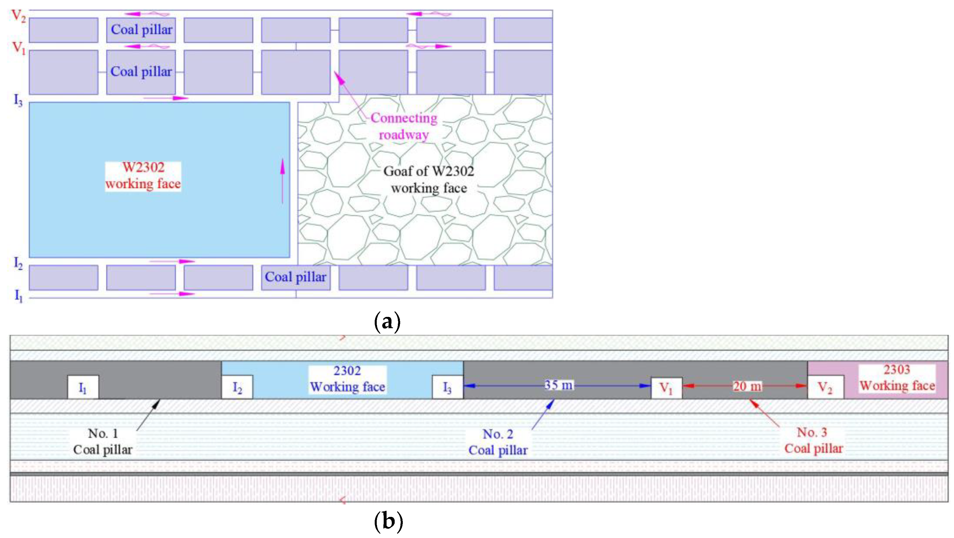
The W2302 working face of Sihe Mine was used as the research site to exploit coal seam 3# in the work. The overall coal seam was flat, with a slope of 1–7° (average 4°), a buried depth of 400–500 m, a thickness of 4.45–8.75 m (average 6.08 m), a strike length of 920 m, and an inclination length of 220 m. The W2303 working face is to the north of the W2302 working face.
Figure 1 shows the roadway layout of the W2302 working face.
There are air-intake roadways 1, 2, and 3# and ventilation roadways 1 and 2# (I1, I2, I3, V1, and V2) from bottom to top. The roadways of coal seam groups are I1, I2, and I3, where a 35 m coal pillar is left between roadways I3 and V1; a 20 m coal pillar is left between roadways V1 and V2.
Fresh airflow enters the working face from roadway I
1, I
2, and I
3 in the stoping process of the W2302 working face, and the dirty air is discharged from roadways V
1 and V
2. After the stoping process, roadways V
1 and V
2 are used as the air intake roadways of W2303. Draining gases at a slow driving speed is challenging when the working face is arranged to excavate the coal seam roadways. The coal pillars cannot be easily recovered after mining, which causes huge resource waste. The following layout scheme is proposed to reduce resource waste and facilitate the pre-drainage of coal seam gas, which can optimize the coal pillar size and solve gas pre-drainage.
Figure 2 shows the roadway layout of the new scheme.
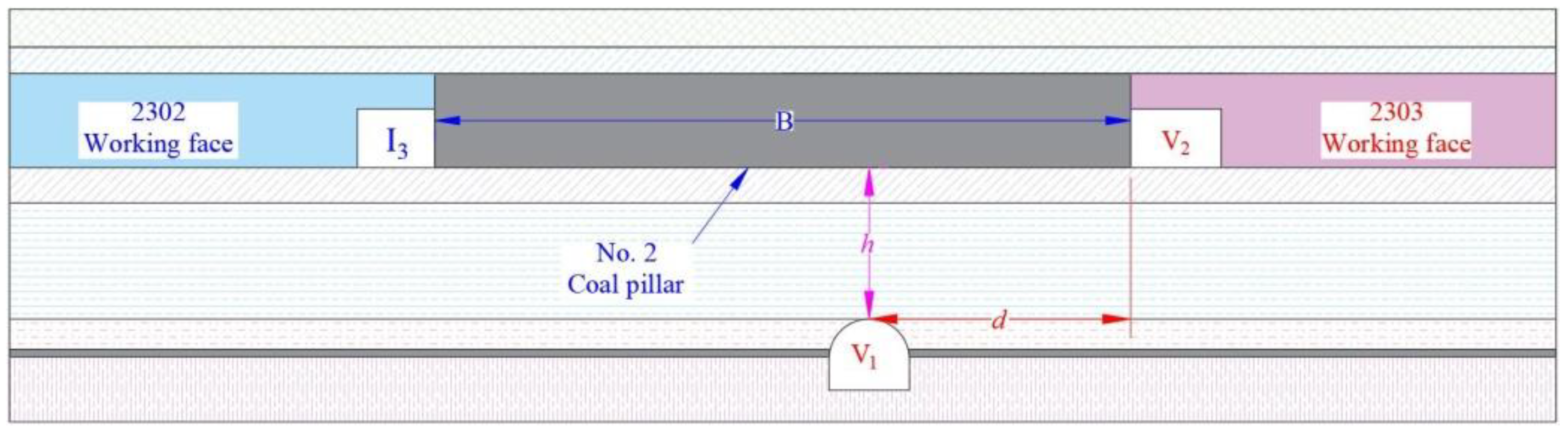
Roadway V1 was firstly excavated in the floor stratum to drain gases existing in the coal seam in advance in the roadway layout. Roadway I3 and V2, and cut holes are excavated when the gas drainage in the coal seam complies with the standard. The original two protective coal pillars were reduced to optimize size. The width of the optimized coal pillar is B, with the unchanged application of roadways. The layout of the W2302 working face is completed after roadways I3, V1, and V2 are excavated. Roadway are the intake airway; roadways V1 and V2 are the return airways. After the stoping of the W2302 working face, roadway I3 was scrapped; roadways V1 and V2 became the intake airways of the W2303 working face.
In the roadway layout, h is the distance between roadway V
1 and the coal seam floor; d the horizontal distance between roadway V
1 and V
2. Too large
h and
d are not conducive to gas extraction. Moreover, roadway excavation requires a large work amount. If
h and
d are too small, then
B is small, and the stability of roadways cannot be easily controlled. When the roadway group on the return air side of the W2302 working face is arranged, B, h, and b (the horizontal distance between roadways V
1 and V
2) are of great significance to reducing coal pillar loss and roadway maintenance costs and improving the drainage effect.
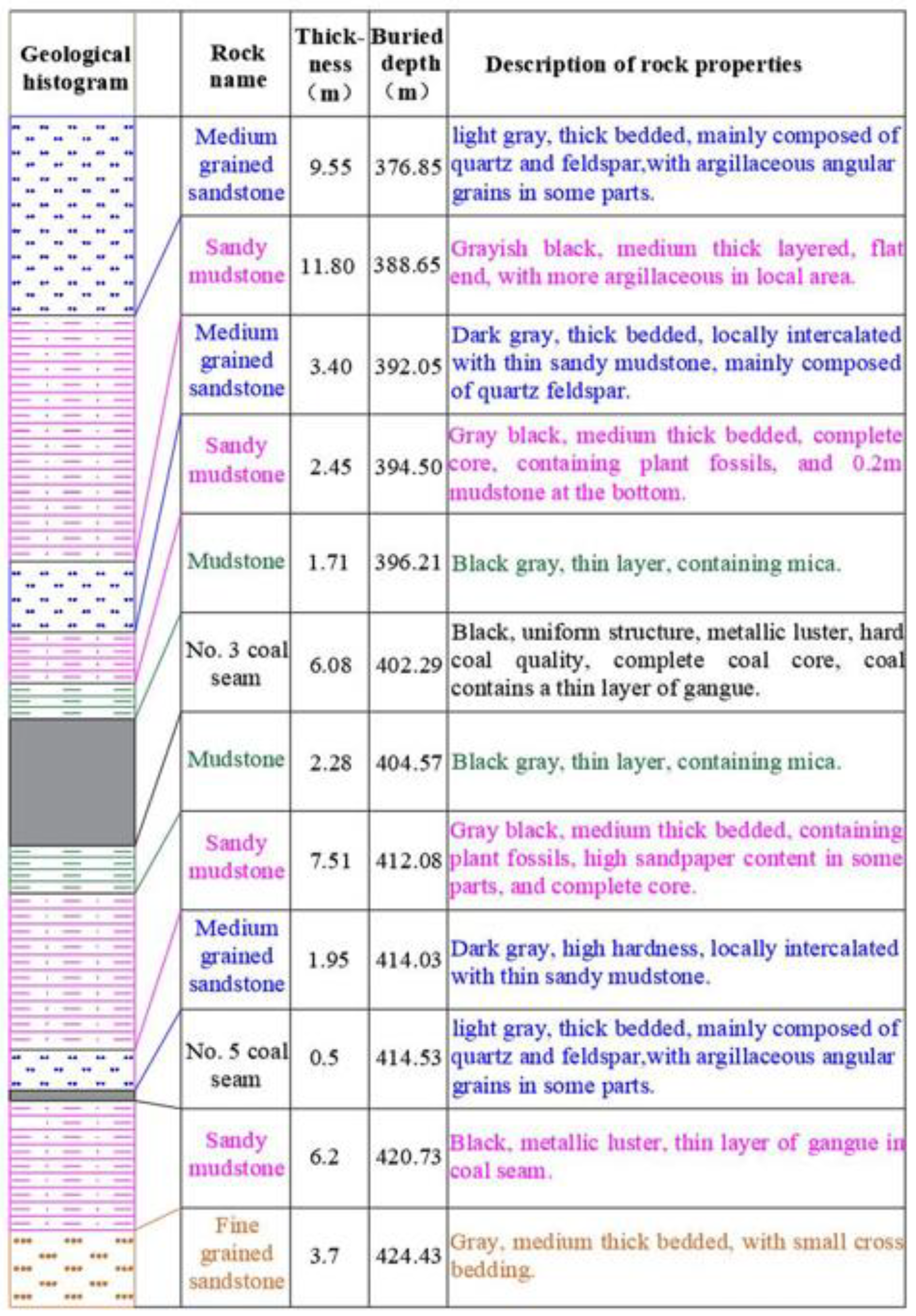
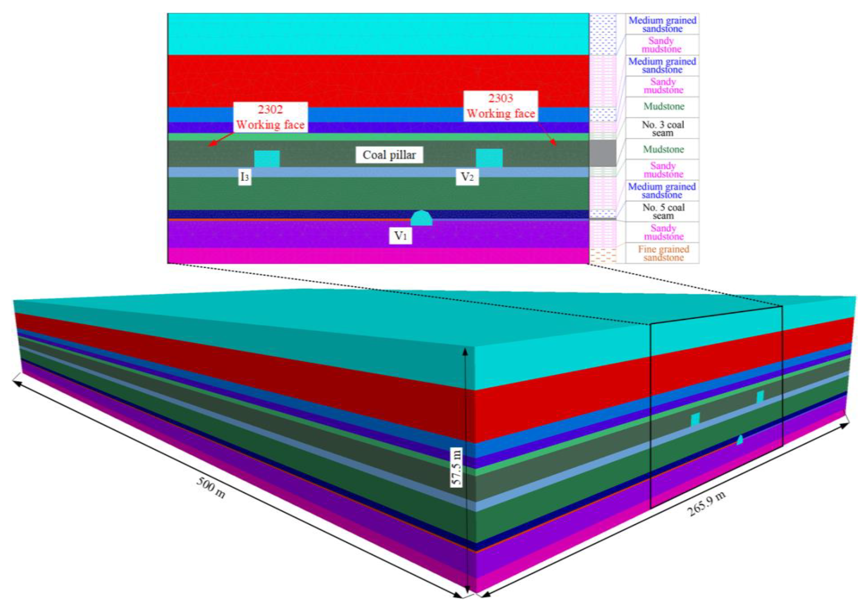
Figure 3 shows the comprehensive geological histogram of coal seams in the mine. According to the classification standard of stope strata in Refs [
22,
23], the mudstone and sandy mudstone in the coal seam roof are the immediate roof; the medium-grained sandstone and the sandy mudstone in the upper layer are the basic roof, the mudstone in the floor of the coal seam is the immediate floor, and the sandy mudstone is the basic floor. Medium-grained sandstone and sandy mudstone in the lower layer are basic floor underlying rock layers. According to the comprehensive geological histogram of coal seams, holes in the roadway I
1 of the W2302 working face were drilled to take the core of the roof and floor, and coal samples were taken in the W2301 working face.
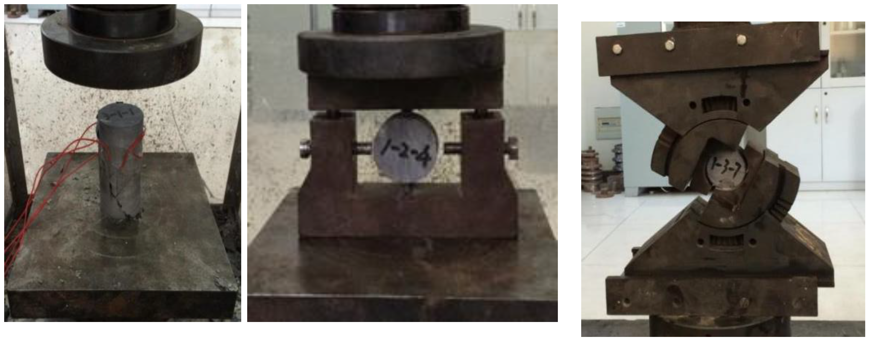
Physical and mechanical properties of surrounding rocks in the stope were explored to solve B, h, and d. Therefore, coal-rock masses were taken on-site in the W2302 working face and processed to prepare samples for physical and mechanical experiments.
Figure 4 and
Table 1 show the experimental process and results, respectively.
According to the laboratory test results, the immediate roof and floor mudstone and sandy mudstone of the working face have low compressive strength. According to the rock classification standard of the coal industry, the immediate roof belongs to the unstable rock stratum. Basic roof medium-grained sandstone and the basic floor medium- grained sandstone underlying rock layers have high hardness and belong to the rock layer with good stability. The strength of sandy mudstone in the basic floor underlying rock- layers is higher than that of the basic floor, which belongs to a medium stable rock layer. It is easy to control the stability of surrounding rocks after excavating the roadway in the sandy mudstone and medium-grained sandstone of the basic floor underlying rock layer.
3. Size Optimization of Coal Pillars and Horizon Layout of the Roadway Group
3.1. Force Analysis of Section Coal Pillars
The vertical stress distribution of the floor strata under the coal pillars on the return air side of the working face is important to the location of floor rock roadways. Therefore, it is necessary to analyze the vertical stress transfer law of the floor strata. The floor rock roadways are arranged in the floor strata with small vertical stress. Coal pillars are more impacted by the spatiotemporal effect of the latest mining of the W2302 working face than the W2303 working face. Support pressures of coal pillars are asymmetrically distributed. Moreover, the coal pillar width should be greater than the sum of the peak ranges of lateral support pressures after mining the two working faces. The section size of the floor stone drift is smaller than the coal pillar width. Therefore, its influence on the coal pillar can be ignored. The above conditions are used to establish a mechanical model combined with mining science and multi-directional mechanics [
22,
24,
25,
26] (see
Figure 5).
The distribution of the lateral support pressures above the coal pillar in the W2302 working face can be described by two curves, and are vertical stress above the coal pillar within and without the lateral support pressure peak, respectively.
Vertical stress above the coal pillar within the lateral support pressure peak is in a limited equilibrium state.
is calculated by Equation (1).
where
is the cohesion of the coal–seam interface, MPa;
is the internal friction angle of the coal–seam interface;
is the bolt support strength, MPa;
is the lateral pressure coefficient of coal pillar internal stress (
);
m is the roadway height (m);
B is the coal pillar width, m; and
x1 is the peak range of lateral support pressure by the W2302 working face, m.
Vertical stress above the coal pillar beyond the lateral support pressure peak accords with Weibull distribution, which can be expressed as:
The relevant parameters of Equation (1) are substituted in Equation (2) to obtain:
where
is the bulk density, kN/m
3;
H is the buried depth of roadways m;
k1 is the mining influence coefficient of the W2302 working face; and
xf is the parameter for adjusting the urgency degree of the function.
In Equation (3), is a unimodal function. When = , . Larger leads to a greater stress peak. Therefore, the stress peak can be adjusted by changing to reflect the influence of working face stoping on the support pressure peak above the coal pillar. There is an inflection point after the peak of . When →, . Therefore, the urgency degree of is adjusted by increasing or decreasing xf in the process of →0 when →.
According to the above analysis, the influence of W2302 working face stoping on stress above the coal pillar is expressed as:
Similarly, the influence of W2303 working face stoping on stress above the coal pillar is expressed as:
where
k2 is the mining influence coefficient of the W2303 working face;
xg is the parameter for adjusting the urgency degree of the function; and
x2 is the peak range of lateral support pressure by the W2303 working face, m.
and
are combined to obtain the stress distribution above the coal pillar.
where
.
When the coal pillar width is large, there must be an original rock stress area in the coal pillar. The external stress of the limit equilibrium area is greater than the original rock stress in the coal pillar. After calculation:
Equation (7) is a transcendental inequality. It is difficult to obtain the critical width of the coal pillar where there is no original rock stress area by the analytical method. Therefore, the graphical method is used to solve the problem combined with elastic mechanics. There is an original rock stress area, correspondingly, k1 and k2 are the on-site measured values.
3.2. Measured Influence Coefficient of Mining Activities
k1 and
k2 in Equation (7) are lateral pressure concentration factors, which need to be obtained through field measurement. The borehole stress meter was selected to measure pressure distribution in the W2301 working face and the coal pillar of the return air side. YHY60 mining intrinsically safe pressure gauge and PZY-60 expansion pressure converter are used for drilling stress gauges.
Figure 6 shows the intrinsically safe pressure gauge and pressure converter. Forty-two expansion pressure converters were installed in the coal pillar at the air return side of the W2301 working face. Thirty-seven borehole stress meters were installed in the coal pillar and thirty-two were installed in the coal pillar whit depths of 2, 3, 4, and 17 and a width of 35 m between roadways I
3 and V
1 of the W2301 working face. Moreover, 5 borehole stress meters were installed in the coal pillar with depths of 3, 5, 9, 12, and 15 m and a width of 20 m between roadways V
1 and V
2. Five borehole stress gauges with depths of 3, 5, 9, 12, and 15 m were installed in the solid coal slope of W2301 working face.
Figure 7 shows the specific installation. The monitoring station was arranged about 150 m away from the working face, which was monitored for 2 months. The drilling stress data were monitored once in the morning and evening shifts each, during the advancement of the working face. Combined with the daily report of the advancement of the working face,
Figure 8 presents the changed internal stress of the coal body and coal pillar in front of the working face with the advancement of the working face.
The support pressure increment on the working face side first increases and then decreases with the decreased distance from the working face. The influence range of advance support pressure is about 100 m; the peak value of support stress increment is about 15 m in front of the coal wall of the working face; the maximum stress increment is about 16 MPa. The internal stress in the coal pillar increases first and then decreases in roadway I3 of the W2301 working face with the decreased distance from the working face. The peak value of the supporting stress increment is about 12 m away from the side of roadway I3, and the maximum stress increment is about 12 MPa. However, the pressure increment in the coal pillar between the two air return roadways changes slightly, and the pressure increment is generally within 2 MPa.
3.3. Location of Intake Airway
According to the geological conditions and relevant test results in Sihe Mine, buried depth of roadway
H = 400 m; stratum density
ρ = 2500 kg/m
3; roadway height
m = 3.8 m; bolt support strength
pi = 0.1 MPa; lateral pressure coefficient = 1; coal–seam interface cohesion
C0 = 0.26 MPa; internal friction angle = 19°, and relevant parameters
xf = 4 and
xg = 4, combined with the change law of the internal stress of the coal pillar, lateral support pressure increasing coefficient
in W2302 working face stoping, the other side is mainly affected by roadway excavation (
). According to Equation (7),
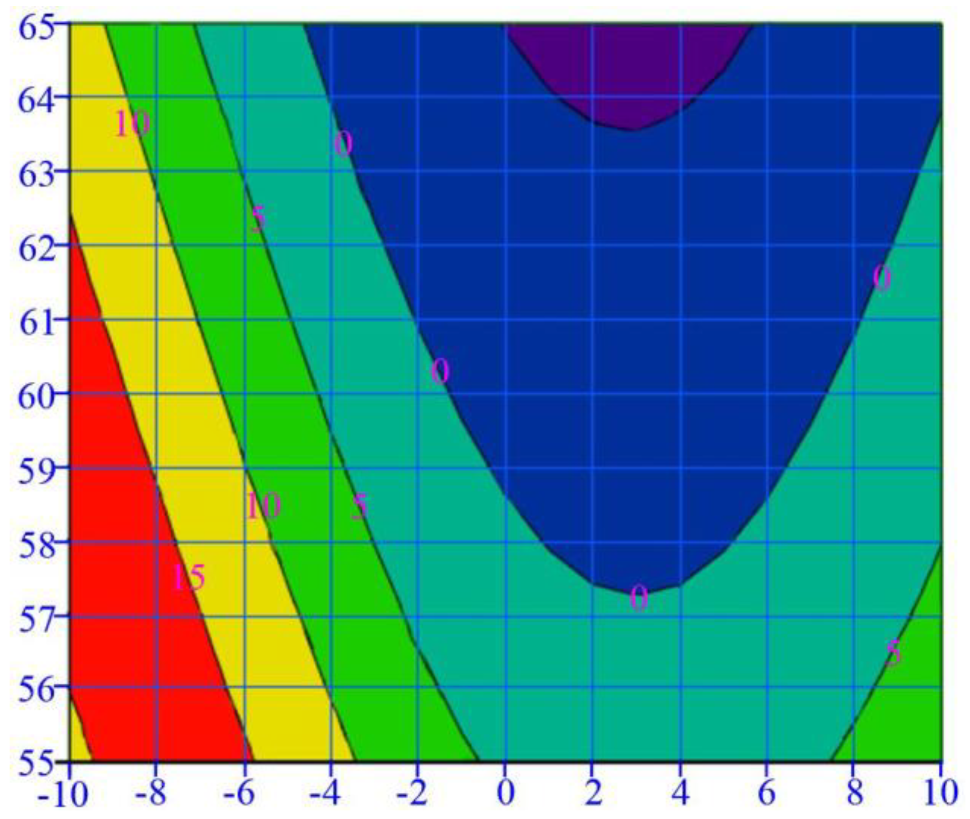
The above relevant parameters are substituted in Equation (7). The mathematical software MathCAD was used to draw the relationship between
and
B (see
Figure 7). The horizontal axis represents the distance from the centerline of the coal pillar; the vertical axis represents the coal pillar width. When
, there is no original rock stress area in the coal pillar.
Figure 9 shows that the critical width of the coal pillar without the original rock stress area is 57.2 m after W2302 working face stoping.
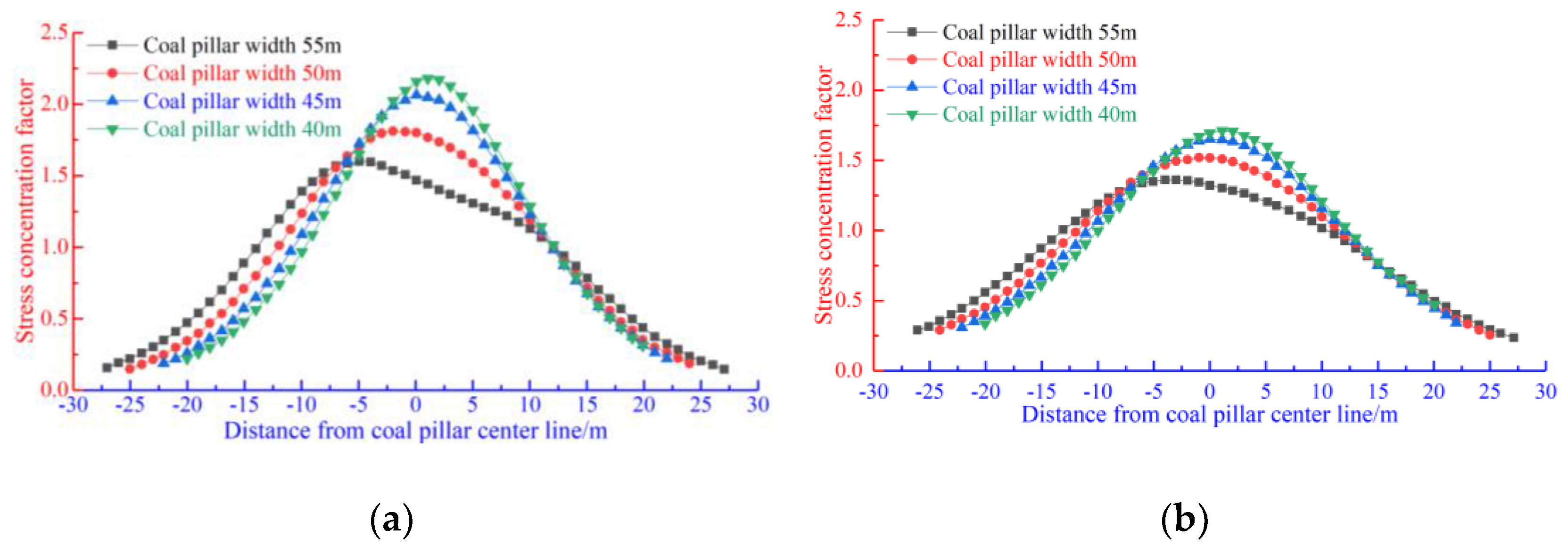
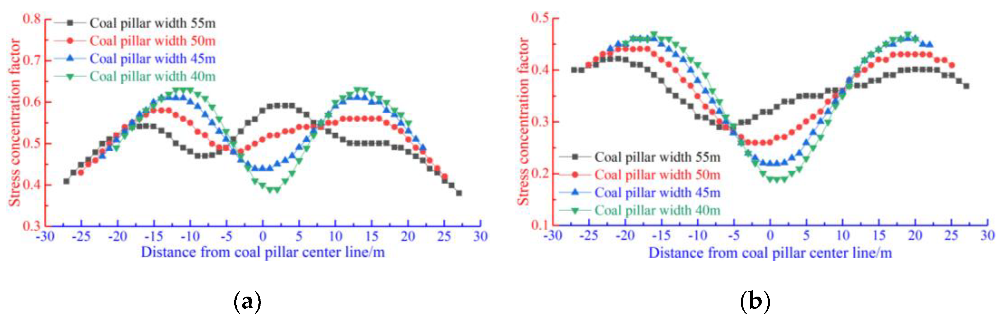
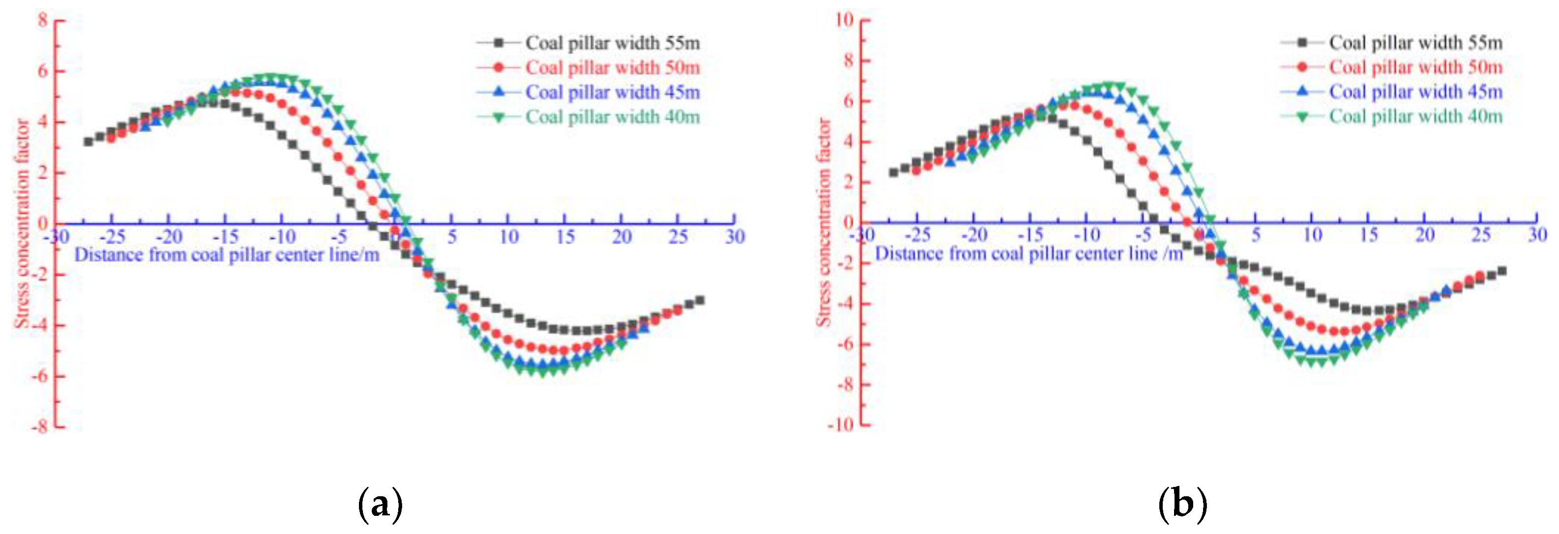
MathCAD was used to calculate the vertical, horizontal, and shear stress concentration factors of the floor strata under different coal pillar widths (see
Figure 10,
Figure 11 and
Figure 12).
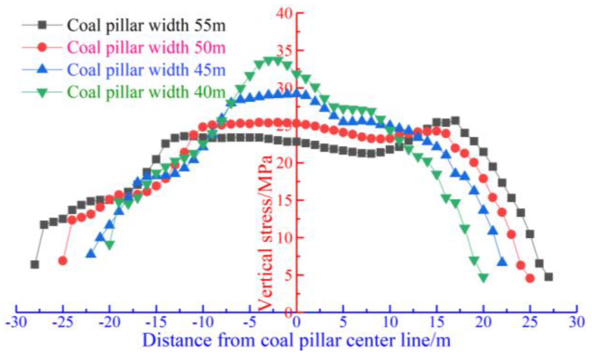
When the coal pillar width ranges from 40 to 55 m, the vertical stress changes greatly at 10–15 m below the coal pillar, with small changes in horizontal and shear stress. Therefore, vertical stress is the most important for the location of the floor rock roadways. The vertical stress concentration factor tends to be equal under different coal pillar widths, about 1 at 10 m below the coal pillar and 12 m from the centerline of the coal pillar. Stress concentration coefficient curves to the left of the point are quite different under different coal pillar widths. When the coal pillar width is small, the stress concentration factor increases rapidly. When the coal pillar width is large, the stress concentration factor increases slowly. Stress curves to the right of this point under different coal pillar widths decrease rapidly, with few differences. The vertical stress concentration factor tends to be equal at different coal pillar widths, about 0.8 at 15 m below the coal pillar and 15 m from the centerline of the coal pillar. The stress concentration coefficient curves to the left of the point are quite different under different coal pillar widths. When the coal pillar width is small, the stress concentration factor increases rapidly. When the coal pillar width is large, the stress concentration factor increases slowly. Stress curves to the right of this point under different coal pillar widths decrease rapidly, with few differences.
From top to bottom, there are 9.8 m sandy mudstone, 2 m medium-grained sandstone, 0.5 m coal seam, and 4.2 m sandy mudstone according to the floor stratum thickness and lithology of coal seam 3# in the comprehensive histogram. The coal seam thickness < 0.3 m in the drilling process near the W2302 working face can be ignored. According to the test results of the mechanical properties of rock, 9.8 m sandy mudstone has a small strength (11.89 MPa); and 2 m medium-grained sandstone has a large strength (50.86 MPa). Medium-grained sandstone is suitable as the roof or both sides of floor rock roadways. Meanwhile, the vertical distance between the floor rock roadway and coal seam is considered to be reduced. Therefore, medium-grained sandstone was used for both sides of the floor rock roadway. Then, the vertical distance between the floor rock roadway and coal seam is 9.8 m.
The floor rock roadway is arranged in the floor area where the vertical-stress concentration factor is less than 1 to avoid the influence of working face stoping on the floor rock roadway, which ensures the stability of the floor rock roadway. According to the stress distribution of floor strata under different coal pillar widths after W2302 working face stoping, the floor rock roadway is not affected by mining of the W2302 working face.
Table 2 shows the horizontal distances between the floor rock roadway and roadway 4 under different coal pillar widths.
5. Actual Measurement Analysis of Roadway Deformation
The coal pillar at the return air side of the W2302 working face in Sihe coal mine was optimized to verify the reliability of the research results and the feasibility of the roadway layout scheme. The width of the coal pillar was set to 45 m, and the roadway V
2 was arranged in the coal seam floor. When the W2302 working face was arranged, roadways I
1 and I
2 were the air return roadways of the W2301 working face. Rock roadway V
1 was excavated first, after excavation, and drill holes in the roadway were drilled to drain the gases in the coal seam, which ensure the safe excavation of roadways I
3 and V
2. After W2302 working face was mined completed, the area with large deformations of roadways V1 and V2 was repaired, and used as roadways I
1 and I
2 of W2303 working face. As the deformation of roadways V
1 and V
2 were relatively slight during the mining process of the W2302 working face, deformation monitoring was not carried out. Surrounding rock deformation of roadway I
2 (the roadway V
2 of W2302 working face) of the W2303 working face was monitored during the mining of the W2303 working face. According to
Section 3, the affected area of advanced stress is 100 m; the accumulation area is about 40 m. Therefore, the first and second stations are 40 and 100 m away from the working face, respectively.
Figure 2 shows the roadway deformation and specific monitoring results.
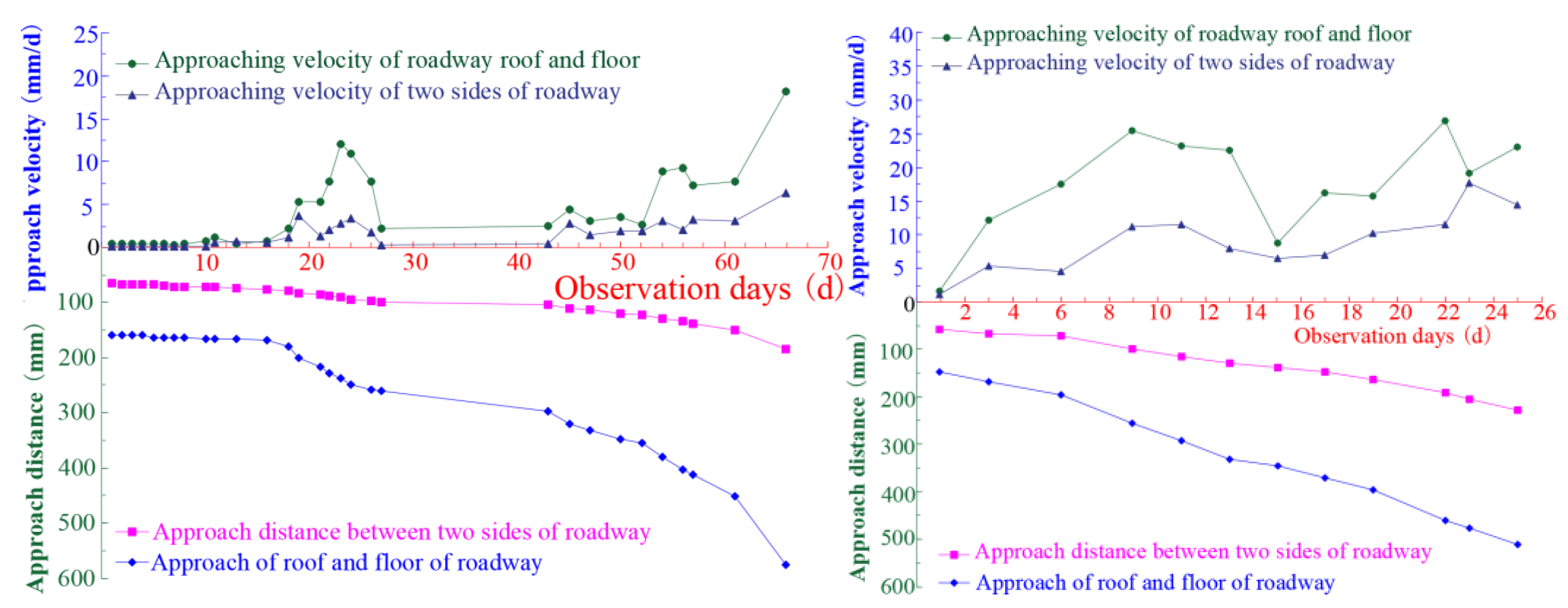
In
Figure 16, the first and second stations are 40 and 100 m away from the working face, with 26 and 66 observation days, respectively. The monitoring results show that the overall deformation of roadways′ surrounding rocks is not large (about 50 mm) at 40–100 m from the front of the working face. When the distance between the measuring point and the working face is less than 40 m, the roadway is greatly affected by advanced stress, which causes severe deformations. The maximum convergence between two sides is 185 mm; the maximum deformation rate is 6.8 mm/d; the maximum convergence between roof and floor is 594 mm; and the maximum deformation rate is 27.5 mm/d. Surrounding rocks of the roadway (intake airway) with certain deformations are available during the service period. The field application results show that the theoretical analysis and numerical simulation results in the work are accurate and reliable, which verifies the feasibility of the proposed coal pillar optimization and roadway horizon layout scheme. The optimized coal pillar can meet the requirements of ventilation, pedestrian, material transportation, and other aspects of roadway surrounding rocks in the service period, which provides a useful reference for similar projects.


