1. Introduction
With the push to achieve international goals of sustainable development [
1] and those focusing on climate change [
2], the energy–environmental aspects and the well-being and safety of occupants are nowadays the two main pillars on which the design of a new building or the renovation of an existing one is based. From this perspective, the transparent envelope of the building has a crucial role, since it affects heat and mass transfer, daylight penetration, sound propagation from outdoor, and thus the thermal, visual, and acoustic comfort of the building occupants [
3]. During the summer, a shading system or reflective glasses adoption can reduce solar gains and therefore the demand for cooling; but, at the same time, they can reduce the natural light amount, and thus they can increase the electrical demand for artificial lighting [
4]. In the winter, this is completely the opposite, with a need to increase solar gains without increasing thermal dispersion. The need to pursue conflicting objectives in two different seasons of the year leads designers to seek a trade-off, which is increasingly difficult to find in the case of such climates as the Mediterranean one [
5]. Nowadays, there are dynamic solutions for transparent building envelopes (smart windows, movable and automatized shading system, and so on) that can meet these needs by changing their status based on the time of day or season [
6,
7]. In many cases, however, their adoption is expensive or short-lived compared to the useful life of the window [
8]. Among static and passive solutions that can be adopted for window systems, light shelves (LSs) can improve the indoor lighting environment and illuminance uniformity, reducing the related lights electricity demand, and, in some cases, manage heat exchange through the window [
9].
LSs are flat or waved surfaces located on the outer side, on the inner side, or on both sides of windows. They can be fixed or movable. Their main characteristic is their finishing material, with optical and spectral features able to reflect part of sunlight incident on the upper surface towards the inner ceiling surface. Based on the ceiling finishing characteristic, the light is further reflected, often in a diffuse manner, to the room environment, achieving strong light penetration and therefore avoiding a dark zone in the back of the room or possible glare near the window. This behaviour, of course, brings a lighting energy saving [
10,
11] but not always an improvement in thermal exchanges [
12]. This is because they modify, often increasing, the solar gain transmitted through the window [
9] with penalty in summertime.
By means of an experimental campaign, Warrier and Raphael [
10] showed that external horizontal LSs can increase the illuminance in the inner zone by 21% on average, but there are some design configurations for which the improvement of daylight penetration or the reduction in glare has not been observed. According to Meresi [
13], external LSs (0.80 m width) inclined by 10° and 20° with a reflection index of 90% and movable external semi-transparent blinds are the best solution for protecting a room from glare and, at the same time, improving daylight distribution. Claros and Soler [
11] with the LS application found not only that the back part of the analysed room was lighter, but also a shading effect of the overhang.
Carrying out a sensitivity analysis and multi-objective optimization, Ebrahimi-Moghadam et al. [
12] showed that in the Iranian climate context for west orientation, five shelves have to be used, with an optimum angle of 24° and depth of 0.57 m, providing a decrease in total energy consumption by 27.819 kWh/m
2. However, the study only considers internal LSs. In the study [
14], it was found that, to save lighting energy and develop a comfortable environment, the application of mobile LS with dimming control and user awareness is more effective compared to horizontal, static LSs and On/Off controls. Additionally, the layout of the investigated room can affect the LS performance [
15,
16]. Mangkuto et al. [
17] carried out an experimental numerical study in an open-plan room of a dental hospital, with east- and west-facing windows.
By means of a genetic algorithm, they only analysed the daylight illuminance, finding that the best LS configuration is: external LS with tilt angle 5° and width 0.90 m coupled with internal LS width 0.40 m in the east exposure; external LS width with tilt angle 25° and 1.20 m coupled with internal LS width of 0.30 m in the west exposure. In this case, the daylight autonomy in the border spaces of the room increased to 89%. Moreover, Xue et al. [
18] studied how clerestory window structures can affect the LSs’ performance, only in terms of the interior illuminance level and uniformity distribution.
From the previous overview emerged that the main factors that affect LSs’ performance are:
Geometry and shape;
Material type and surface optical characteristics;
Position and inclination;
Characteristics of the room surfaces and its layout;
Outdoor climatic conditions;
Indoor user behaviour.
Meanwhile, their application could affect different domains:
Thus, for an in-depth analysis, it will therefore be necessary to study the whole window–LS–ceiling system, which is the aim of this paper. Since there are a great number of possible window–LS–ceiling system configurations and different areas of interest, the developed method has novelty aspects, since it implements a multi-objective optimization based on genetic algorithms (GA) within an interoperable workflow with mutual start and end points, building a model in a BIM environment.
2. Methodological Approach
When a global optimization method is unavailable or the optimization result is in doubt, parametric tools can be used to explore a comprehensive variety of design options.
Additionally, parametric analysis can be applied to all design variables at the same time, resulting in an exhaustive search that guarantees the discovery of the global optimum solution on a fine mesh. To make this possible, specific tools are required to create and manage all the simulations involved to perform complex parametric analysis on multiple design options and to collect and visualize the results.
The assessment of the energy demand and lighting of buildings, in a given context, requires an integration between input data, which can sometimes be very raw and unreliable, and detailed building-scale simulation models.
In order to optimise the design of a building and its components and perform calculations and simulations, it is essential to have a comprehensive information model and data that take into account the building’s architectural aspect, energy, and resource consumption, as well as external and internal comfort factors.
Architectural projects are complex processes, which must be linked to design in an operational way. In this sense, parameters are all the categories of information that affect decision making when carrying out a project. This is the goal of parametric analysis: to go beyond geometry and form to design a system that includes all variables/categories involved in the design process. Therefore, the potential offered by modern parametric software tools and programming frameworks (Revit, Dynamo, etc.) is the possibility to improve the design process.
The most important initial data used in the energy analyses and optimizations are those from the architectural model. For this reason, and to eliminate the gap generated by approximate input data, a BIM model is a suitable tool for the implementation of parametric analysis, as its nature makes it possible to explore different design solutions, combine and design different building elements and parameters, and to create a digital model that is able to adapt effectively to the objective of the design and construction.
Moreover, the parametric method has remarkable results in the interactive design process; in fact, similar results are rarely obtained by conventional methods. To use optimisation as an integral tool in design processes, users must have a sufficient level of control over how the optimisation process works.
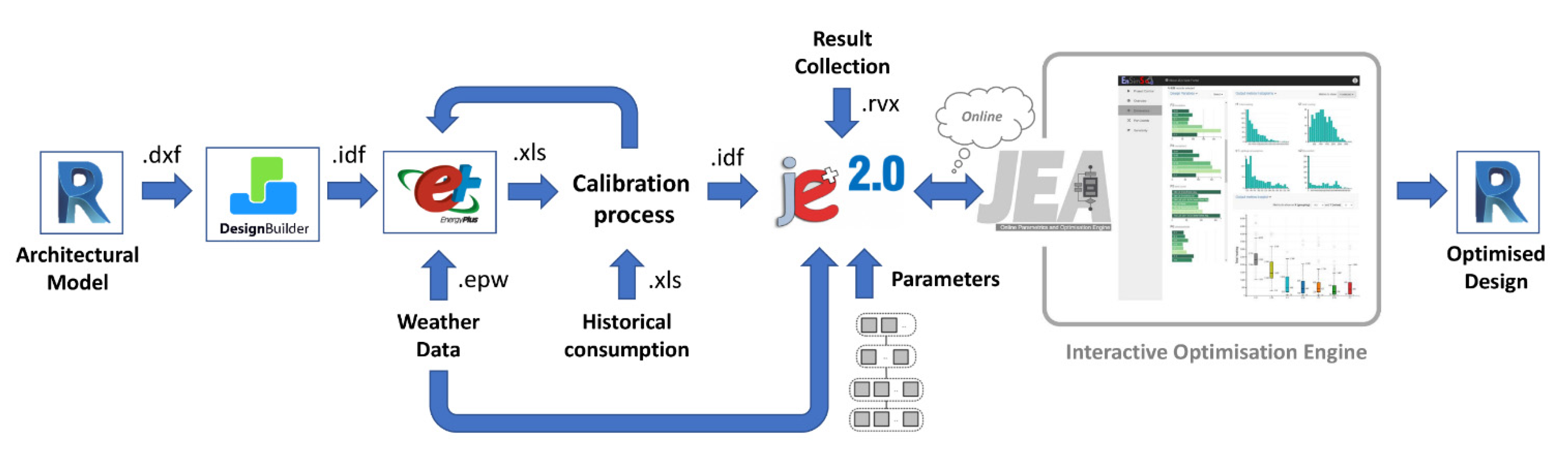
The workflow proposed for this case study accommodates a combination of form parameters with various assessment tools and algorithms, as shown in
Figure 1.
The starting point of the process is the architectural model of the building in its existing state, developed in REVIT by means of traditional in-field inspections and innovative methods such as 3D laser scanning. Thus, the geometry definition with dimensions and positions of the thermal envelope was conducted by means of DesignBuilder software [
19]. The HVAC system, as well as all indoor gains and their schedules, was developed in the EnergyPlus engine [
20]. The simulation, conducted considering the suitable climate file, yielded results that were then compared with the real historical consumption of the building in order to calibrate the numerical model developed. After this phase, the model can be considered faithful to reality under an energetic point of view. Consequently, the LS is designed in the model, and the optimization process starts.
Regarding the optimisation tool, jEPlus+EA is used, an open-source tool originally developed for managing complex parametric simulations using EnergyPlus (E+), that, combined with optimisation algorithms such as evolutionary algorithms (EAs), provides a convenient and highly efficient way to perform optimisation for building design and operation [
21].
The first step in jEPlus is to import an IDF file generated by the previous EnergyPlus simulations and place a number of search strings inside the file to mark the locations of where the parameter values should be applied, then specifying all the alternative values for the parameters.
Once we have defined the parameters, jEPlus creates a list of cases and simulation for EnergyPlus, each case containing a unique set of parameter values placed in the .idf model. In this way, is possible to quickly set up a large amount of simulation runs to explore the parametric space. After the pre-processes, jEPlus run simulations on each selected case until completing the process. Once the simulations are completed, it uses the information defined in the RVX object in the project to collect results [
21].
The results obtained are sent to the JEA optimisation engine. JEA is a multi-objective constrained algorithm based on EAs and has been tuned for a wide range of problems found in applications in the built environment. Additional methods such as parametric analysis and uncertainty/sensitivity analysis are provided to aid the interactive design approach [
22].
It is suitable for both multi-objective and single-objective problems, constrained or unconstrained, and allows full interactivity with the on-the-fly adjustment of algorithm configuration, search space, optimisation criteria, and evaluation models.
The most important new feature is the interactivity supported by JEA, which allows users to [
22]:
Check and manage the search process progression;
Modify, add, or remove parameters and configurations as well as optimisation criteria and design options;
Combine and/or change simulation models;
Collaborate with other users online.
These functions have made it possible to improve the entire optimisation process compared other current optimisation tools, which, for most users, work like a “black box”. Indeed, one problem with current optimisation tools is that the user cannot do much more than wait to see whether they eventually obtain the desired results, so, with an interactive optimization process, it is possible to avoid innocent mistakes in setting up the problem or configuring the algorithms, which could easily lead to significant time losses [
22].
Finally, because of this process, the obtained data were reconfigured in the BIM model (
Figure 1).
3. The Case Study
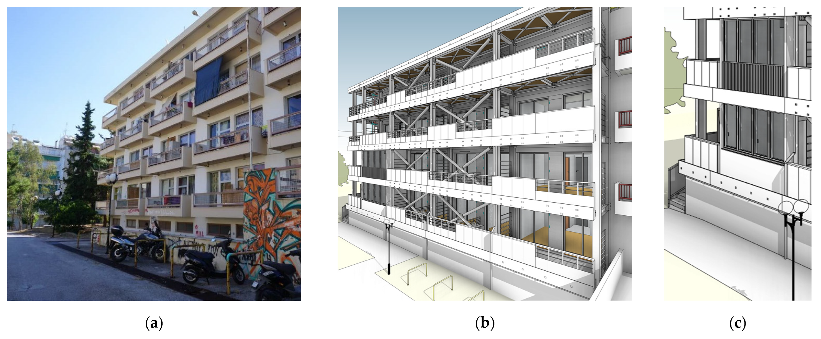
The present study refers to a real student dormitory located within the University Campus of the National and Kapodistrian University of Athens. The building was built in 1986. The structure has a rectangular shape (56.6 m × 15.4 m) with an overall gross building area of approximately 3642 m
2. There are four floors above ground and a basement. Each floor, with an area of 725 m
2, hosts 36 single-bed rooms for students, except for the ground floor, which hosts 30 rooms (
Figure 2a). The building is today subject to extensive energy renovation towards nearly zero-energy building (nZEB) under the framework of the H2020 European project Pro-GET-onE (
Figure 2b). The project aims to propose an integrated approach for refurbishing the existing buildings under seismic and energy point of view by means of integrated efficient technology (known as GET). The refurbishment of the dormitory aims to: add new living-spaces; replace the HVAC system; improve the thermal performance of the building envelope; integrate renewable energy systems; and replace the electrical equipment and lighting system.
The whole project is “BIM oriented”, which means that the design methods and the decision-making processes are completely supported by BIM methodology in order to maximize collaboration and information exchange between all the partners. Furthermore, using BIM to renovate existing buildings allows one to optimize the production of the component in off-site factories, their transport to the construction site, and the on-site assembly. The main goal is to improve the project’s efficiency, promoting circular and sustainable renovation processes [
23,
24].
With the new configuration, some rooms are subjected to an extension of their space, with the application of the so-called extra room as GET system. For better understanding the layout of the rooms under investigation, a zoomed image in
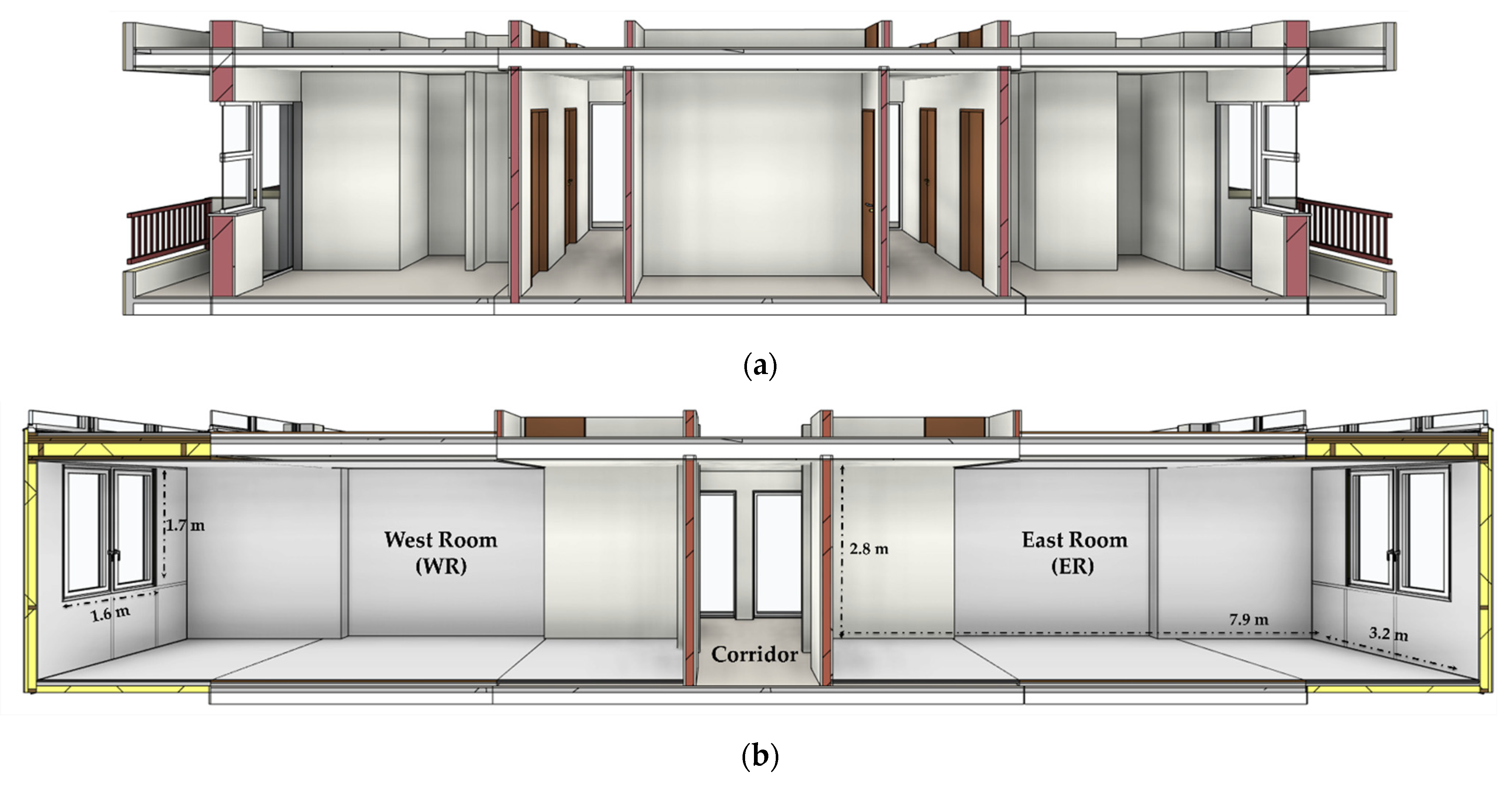
Figure 2c has been added. So, the old rooms of 9.50 m
2 (
Figure 3a) after the refurbishment will have a net floor area of 23 m
2 and one window of 2.7 m
2 with a parapet 0.8 m high. For the present study, two representative rooms have been considered, one approximately west-facing (henceforth, the acronym WR will be used) and the other one approximately east-facing (ER), of a representative floor (the first one). The two rooms are identical in geometry, form, and materials; they only have different exposures. The layout is shown in
Figure 3b. As can be seen, the rooms under investigation are narrow and long; therefore, they are particularly suitable for the application of LS for improving the illuminance level in the in areas away from windows.
4. Window–LS–Room System Design and Parametric Analysis
The simulations of the LS within E+ are carried out using the
SplitFlux method for the daylighting model and the
Conduction Transfer Functions algorithm for the thermal analysis, as described in [
25]. The LSs are simulated using the object called
DaylightingDevice:Shelf in E+. In particular, the internal LSs are considered a regular heat transfer surface in the room, with thermal mass and shading effect taken into account in the simulation. The outer LSs reflect sunlight based on their visible and solar absorptance [
26].
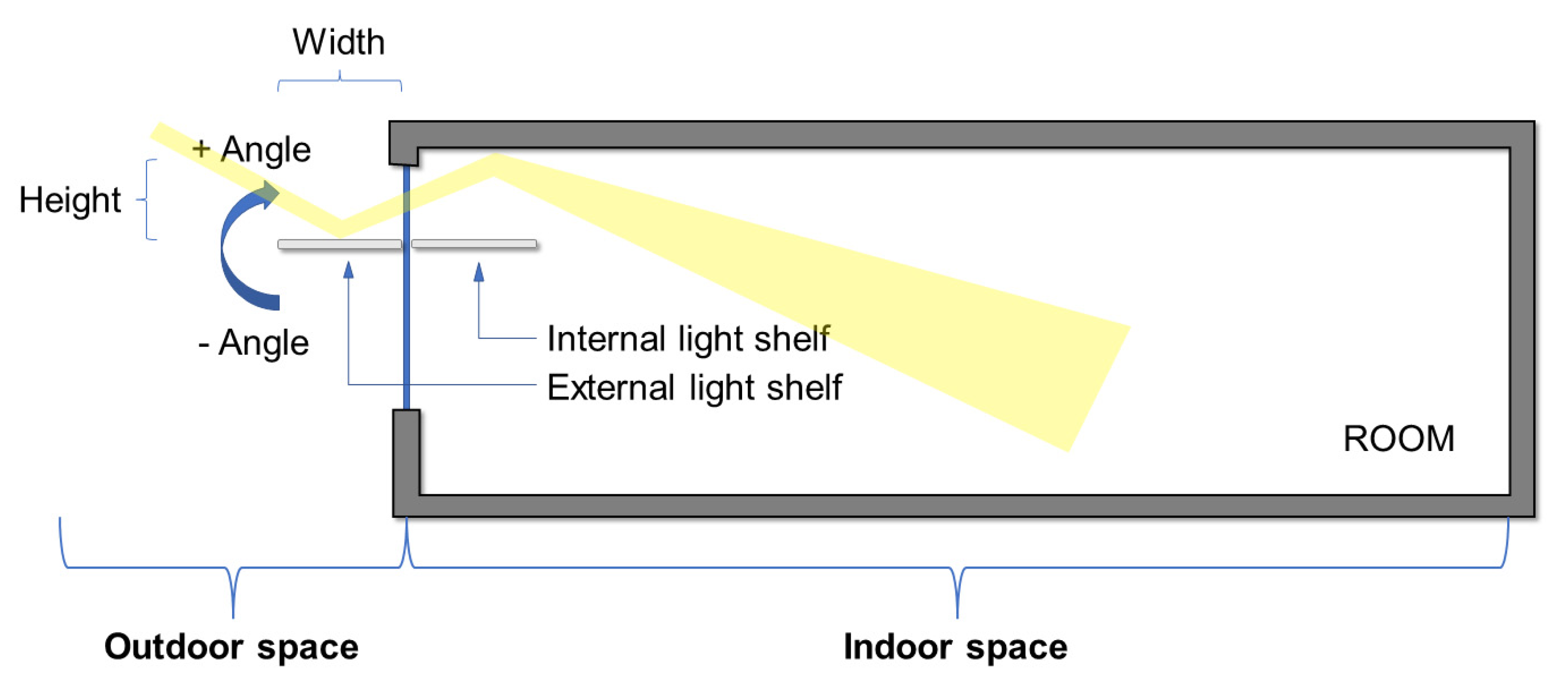
For the design of the LS, a horizontal solution has been considered, both internal and external, as shown in
Figure 4. The
Height refers to the distance from the top of the window, the
Width is the length of the LS, both internal than external, and the
Inclination refers to the rotation angle of the LS with respect the normal to the window, for both internal and external LS. So, all these geometrical characteristics, as well as thickness, materials, and finishing, have been considered parameters of the study, according to the main design criteria in the scientific literature [
9]. For coding the geometrical aspect, the string
LS_Position_Height_Width_Inclination angle is used, where the values set for them can be read in
Table 1. For instance,
LS_in_5060+15 refers to the inner LS with a distance from the top of the window of 50 cm, a width of 60 cm, and upward tilt of 15°. All developed characteristics with the proper acronym (ID) are reported in
Table 1. For instance, in addition to several geometric configurations, various materials have been taken into account (e.g., wood, plastic, metal, and glass), the thermophysical characteristics of which, such as thermal conductivity (λ), density (ρ), and heat capacity (c
p), have been set considering the ISO 10456 standard [
27]. The material properties affect the result, because, with respect to the case without LS, an additional mass placed near the window (indoor or outdoor) can heat up, and it can exchange heat on the basis of its thermo-physical and spectral characteristics. Another important parameter considering dynamic heat transfer is thermal diffusivity (α). Since it depends on λ, ρ, and c
p, it is also considered in the simulations.
The spectral characteristics of the finishing type have been modelled by varying the visible absorptance, the solar absorptance, and the thermal absorptance. Following the used tool data input, the thermal absorptance is the fraction of incident radiation in the long wavelength (>2.5 µm) absorbed by the material. It affects the surface heat balances because it is used for calculating the radiant exchange between the surfaces. In that specific wavelength range, the thermal absorptance is equal to the thermal emissivity, while the solar absorptance represents the fraction of incident solar radiation (0.3 ÷ 2.5 µm) that is absorbed by the material; thus, it includes the visible, infrared, and ultraviolet spectrum. This parameter also affects the surface heat balances because it considers the amount of incident solar radiation absorbed by the surfaces. Its value is complementary to one of solar reflectance. Finally, the visible absorptance considers only the fraction of incident visible wavelength radiation (0.37 ÷ 0.78 µm) absorbed by the material. It differs from the solar band radiation because the visible wavelength radiation interval is much narrower than the solar one. This parameter affects both surface heat balances and daylighting calculations.
For the windows, two glazing types—double and triple—with three different surface treatments—float, low emissivity (Low-E), and reflective—were selected. Their performance, in terms of glass thermal transmittance (U
g), solar factor (g), and visible transmittance (τ
vis), were set according to the standard EN 13363 [
28]. The float glass was considered because the study involves daylighting as an objective variable, so considering a glass with high values of visible transmittance (τ
vis = 0.82) could yield interesting results. On the other hand, float glasses do not have the same energy performance as low-e or reflective ones. Thus, the pareto-front outcomes will give information about the best one.
Finally, the interior context of the room, in terms of finishing type and the radiative characteristics of walls and floor, has been considered, since it also affects the performance of the LSs. The main characteristics are surface rigidity and surface visible absorptance.
Considering all possible permutations, in total, 2,843,100 configurations of window–LS–room have been considered and simulated. It is evident that there is a need to use a multi-objective optimization methodology that, requiring fewer simulations, can solve problems with numerous design variables and alternatives. Moreover, the genetic algorithms could easily process a large amount of data to identify the pareto front [
29].
Since one of the of objective functions of the study, as will be shown in the next section, is the electricity consumption of artificial lights, the description of the lighting modelling is here reported. The LED lamps system has presence and illuminance level sensors, active every day, from 7:00 to 24:00. The control is linear; thus, as the daylight illuminance increases, the lights dim linearly and continuously from 5 W/m2 (the maximum electric power) to 0.5 W/m2 (the minimum electric power). The sensors are put in the centre of the room, 0.8 m from the floor, because this is the height of a possible work surface of a student in the dormitory.
5. Results of Multi-Objective Optimization
As said, the evolutionary algorithm used in this study effectively searches the design space to seek optimum solutions that best fulfil the design objectives. Considering the technology investigated and the different disciplinary fields that it can affect, two objectives have been chosen:
Maximizing the Daylighting illuminance level (t0). It affects how much electric lighting can be lowered and the visual comfort of the student.
Minimizing the Total Cooling Need (t1). It affects the final energy demand and the thermal comfort of the occupant.
Daylighting illuminance level is evaluated on the work plane for studying, while the total cooling need is the energy demand of the room, without considering the plant in the simulations. Finding a solution that increases the illuminance level could lead to an increase in cooling energy but a reduction in electricity for lights. On the other hand, a reduction in electricity for lights could lead to a reduction in cooling rate. The two objectives are linked. It is therefore essential to find a trade-off between these two conflicting objectives to optimize the characteristics of the light shelves and achieve ideal interior comfort.
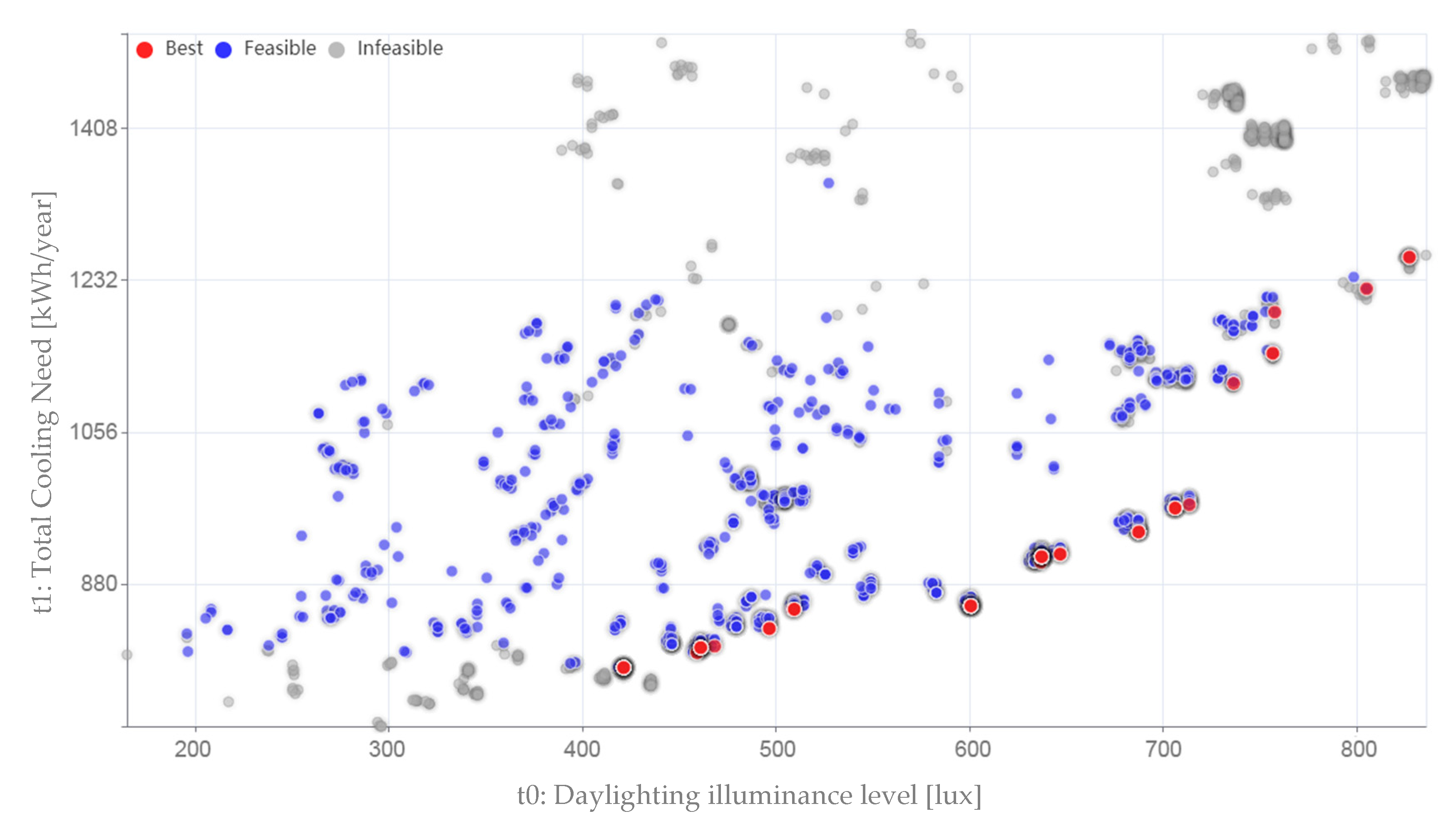
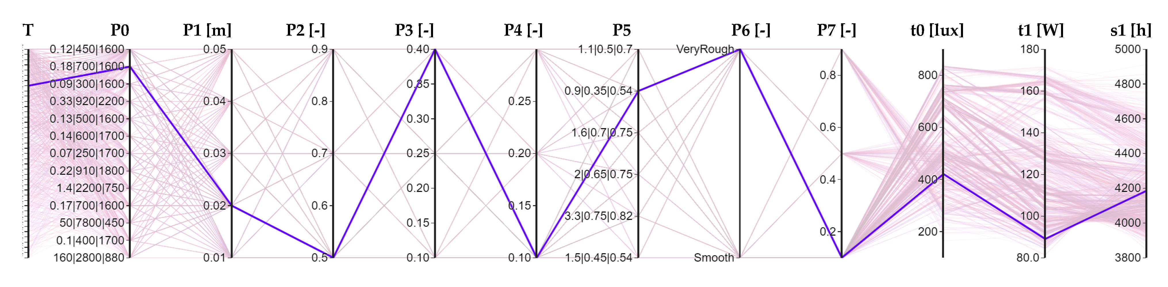
In
Figure 5 and
Figure 6, the results of the optimization are reported for ER and WR, respectively, highlighting among feasible (blue points) and infeasible (grey points) solutions the best ones in red (Pareto front). To choose the feasible solutions, only the ones that reduce the number of discomfort hours (code s1) with respect to the state without LSs is considered. For discomfort hours, the sum of the hours, over the whole year, in which the combination of operative temperature and relative humidity is not in the comfort region defined by ASHRAE 55 [
30] model (with summer or winter clothes) is considered. The region being referred to is characterized by a humidity ratio changing from 0.012 to null value both in the summer and in the winter, and an operative temperature increasing from approximately 20 °C to 26 °C in the winter and approximately 24 °C to 28 °C in the summer, varying with humidity. In these ranges, the analytic indexes for determining thermal comfort, PMV (predicted mean vote), and PPD (predicted percentage of dissatisfied) show comfort environmental conditions (PPD less than 10% with −0.5 < PMV < +0.5). The ranges have been evaluated considering, for summer, a clothes insulation level of 0.5 Clo and, for winter, of 1.0 Clo. So, ideally, we would expect zero discomfort hours all year round, but it is impossible because this global index (number of discomfort hours) also considers the intermediate periods, in which, for example, in spring, the outside temperature is still high, but the Clo value has become 0.5. Thus, it is necessary to obtain a global comfort index, used as relative term with respect to the base case, for the choice scenarios that improve the existing case, and not to be taken into consideration in absolute terms.
Hence, infeasible solutions are the ones with discomfort hours greater than 4188 for the ER and greater than 4487 for the WR. This choice allows, on one hand, to reduce the number of solutions and, on the other hand, to choose solutions that have improved thermal comfort conditions with respect to the state without LSs. In total, 200 generations were developed.
Considering the best solutions in
Figure 5, as the illuminance daylight increases, the cooling need increases; this because the increase in daylight could be brought, for instance, by the application of float glasses, which show the greatest visible transmittance (τ
vis = 0.82) but also the greatest solar factor (g = 0.75). Given the choice of the type of control of the lighting system, the increase in daylighting is directly proportional to the decrease in lights’ electricity. In total, 112 best solutions have been found. Their characteristics will be further explored in the following sections.
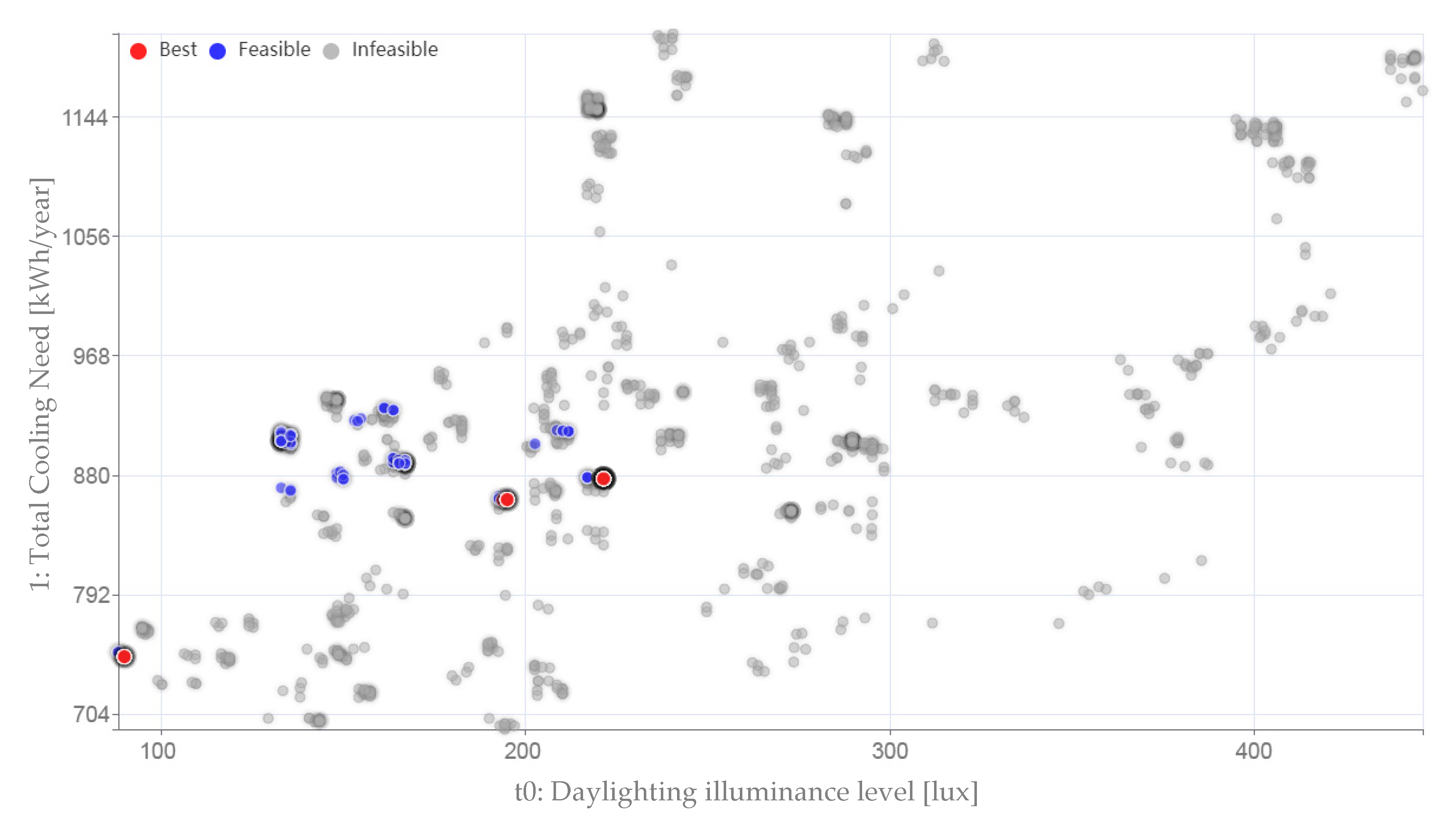
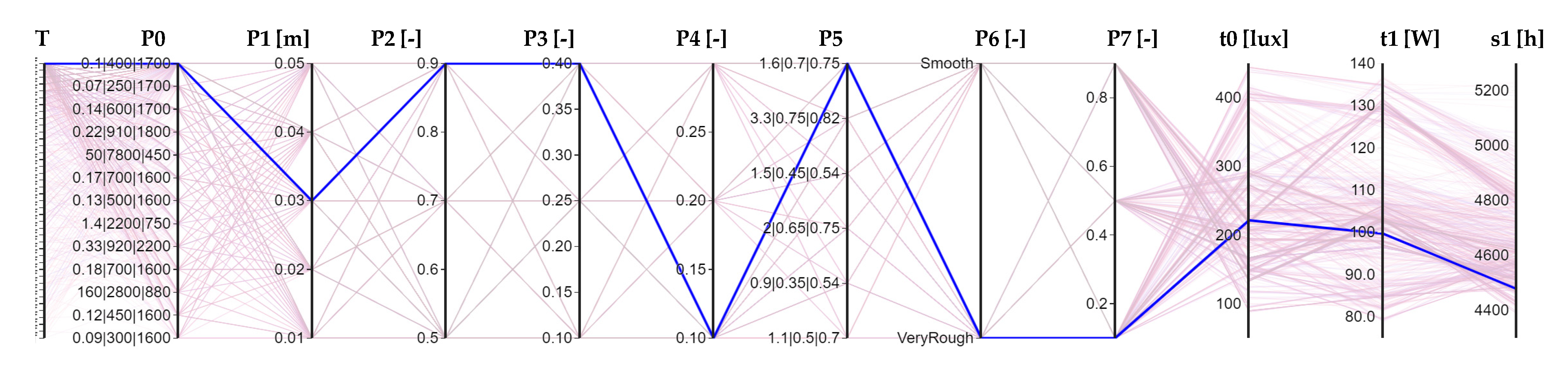
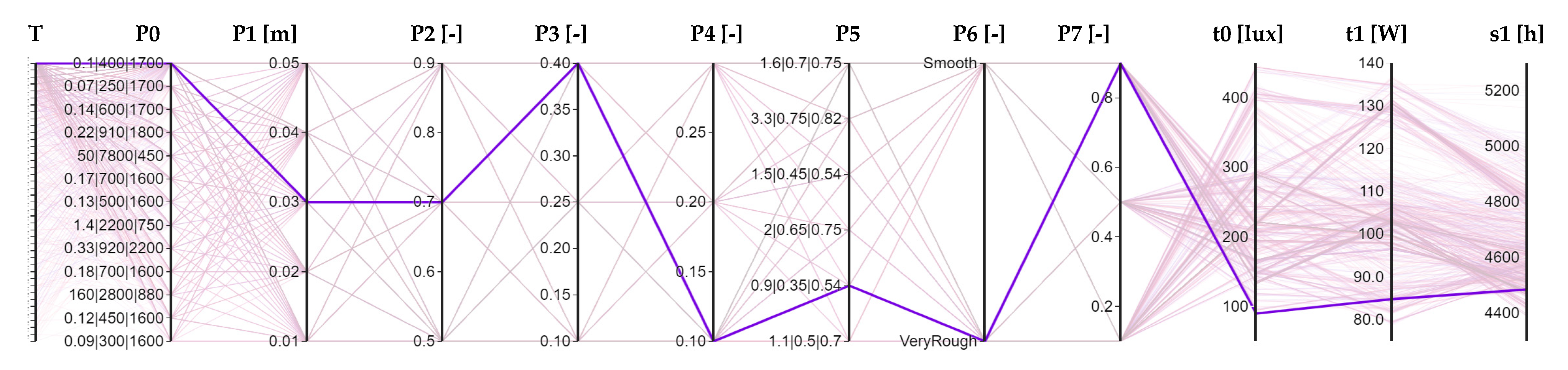
Regarding the west room (
Figure 6), there are more infeasible solutions (grey points), which help the designer to faster find a most suitable best solution. In this case, the red points are 233; most of them overlapped. Similar considerations of the previous graphs could also be made in this case.
The fewest optimal solutions in the case of WR, after fixing the maximum number of discomfort hours, could depend on the problem of properly shadowing solar radiation on the west side if a horizontal shield is used.
5.1. Single Parameter Analysis
The platform used in this study (the interactive optimization engine) allows us to have a lot of graphs to view the results, interactive and editable by the various users with whom the project is shared, for instance, histograms, boxplots, bubble chart, and scatter graphs.
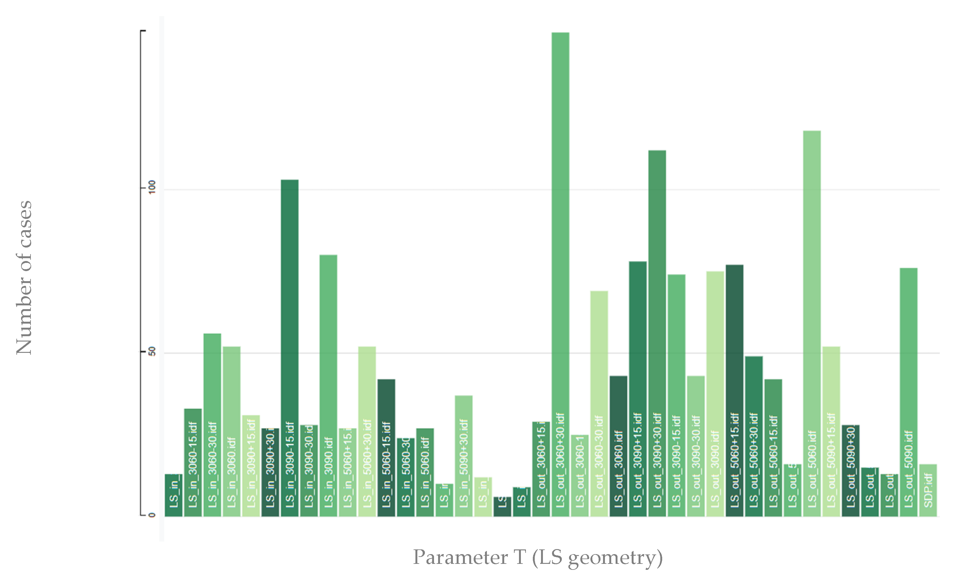
In this section, each parameter shown in
Table 1 is analysed. The number of occurrences of a certain parameter in the feasible solutions (including the best ones) is shown in the histograms.
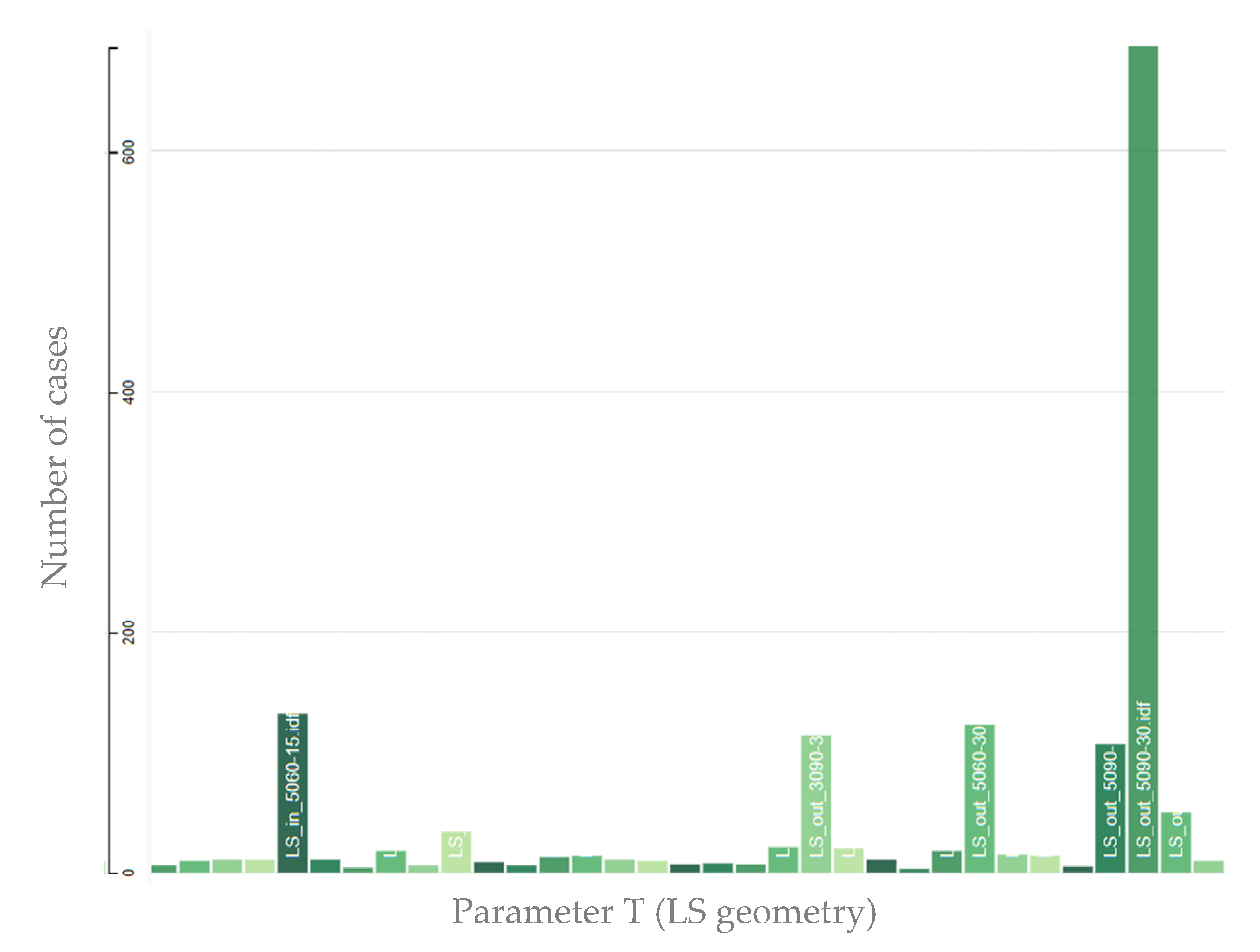
Figure 7 refers to the T: LS geometry. The configuration most recurring (148 times) in the feasible solutions is LS_out_3060+30, followed by LS_out_5060 and LS_out_3090+30. Thus, the external LSs solutions with the highest positioning recur more. On the other hand, the internal solutions are less recurrent. An explanation for this can be given by the fact that, among the two objectives, there is the minimization of the cooling need, and since the external LSs in the simulation are modelled as a shading surface, they are to be preferred.
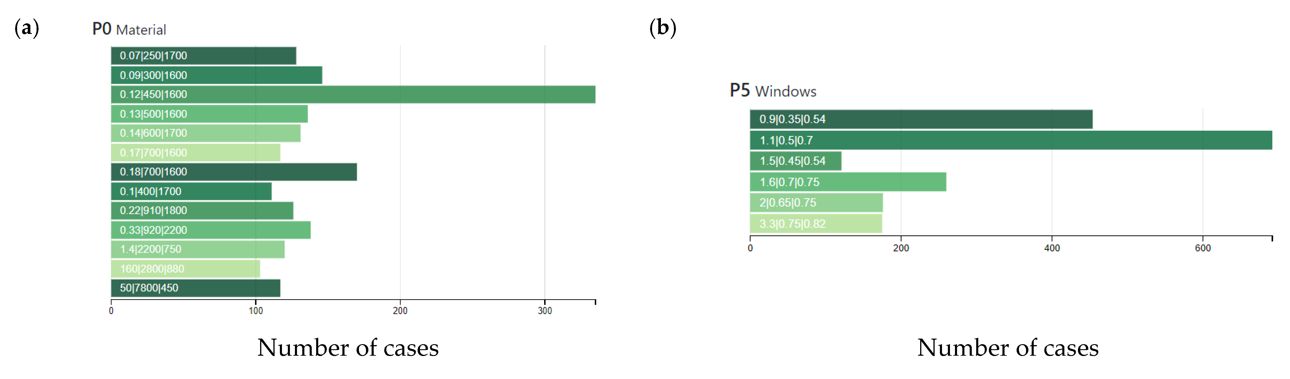
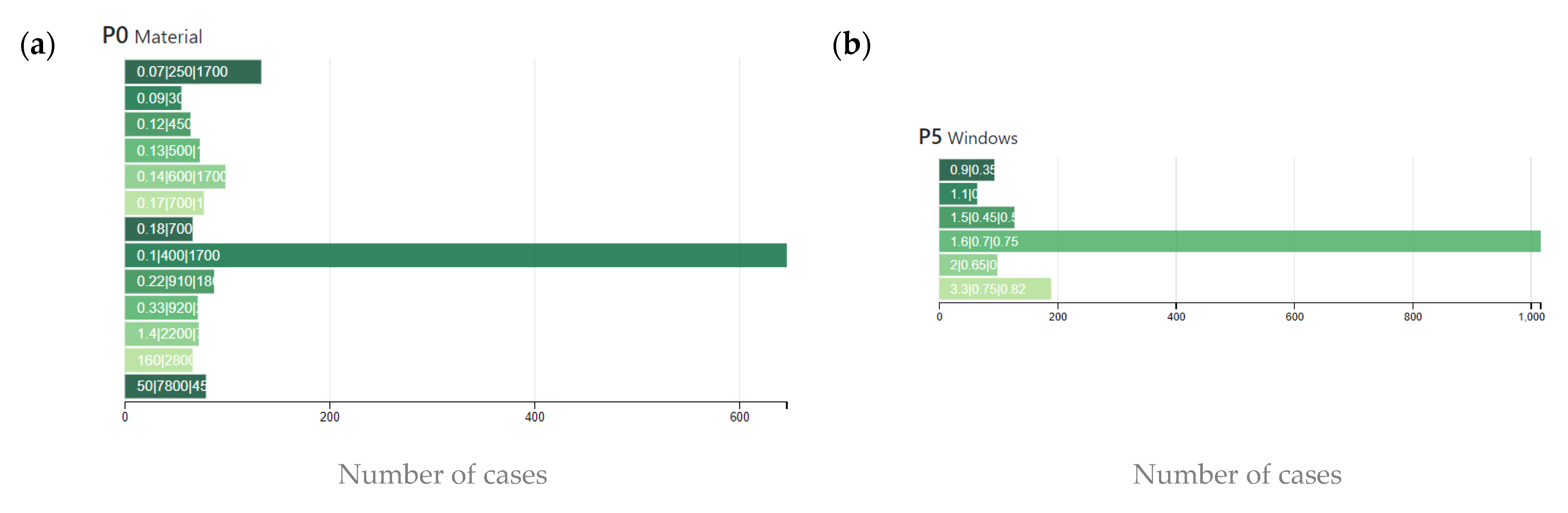
Figure 8a depicts the occurrence of P0 parameter (LS material). The three numbers shown on the bars are λ|ρ|cp. The material with the maximum number of occurrences is timber with 450 kg/m
3 density (335 times), followed by timber with 700 kg/m
3 density (170 times). The least recurring material is aluminium (103 cases). It should be noted that the more frequently recurring solutions are characterized by low thermal conductivity and mean heat capacity. In this way, the shelf takes longer to store thermal energy, avoiding the possibility of a warm surface near the window, thus pursuing the objective t1. In
Figure 8b, the parameter P5, glass material, is shown. In this case, the values of U|g|τ
vis are reported. It could be seen how the most recurring solution (692 times) is the triple glazing Low-E, followed by the reflective one. This because, since there are opposite objective functions (cooling need minimization and daylighting maximization), the low emissive glass shows greater τ
vis (0.70) but greater solar factor (g = 0.50) with respect to the reflective solution, thus could be preferable under the daylight point of view and not under the cooling point of view.
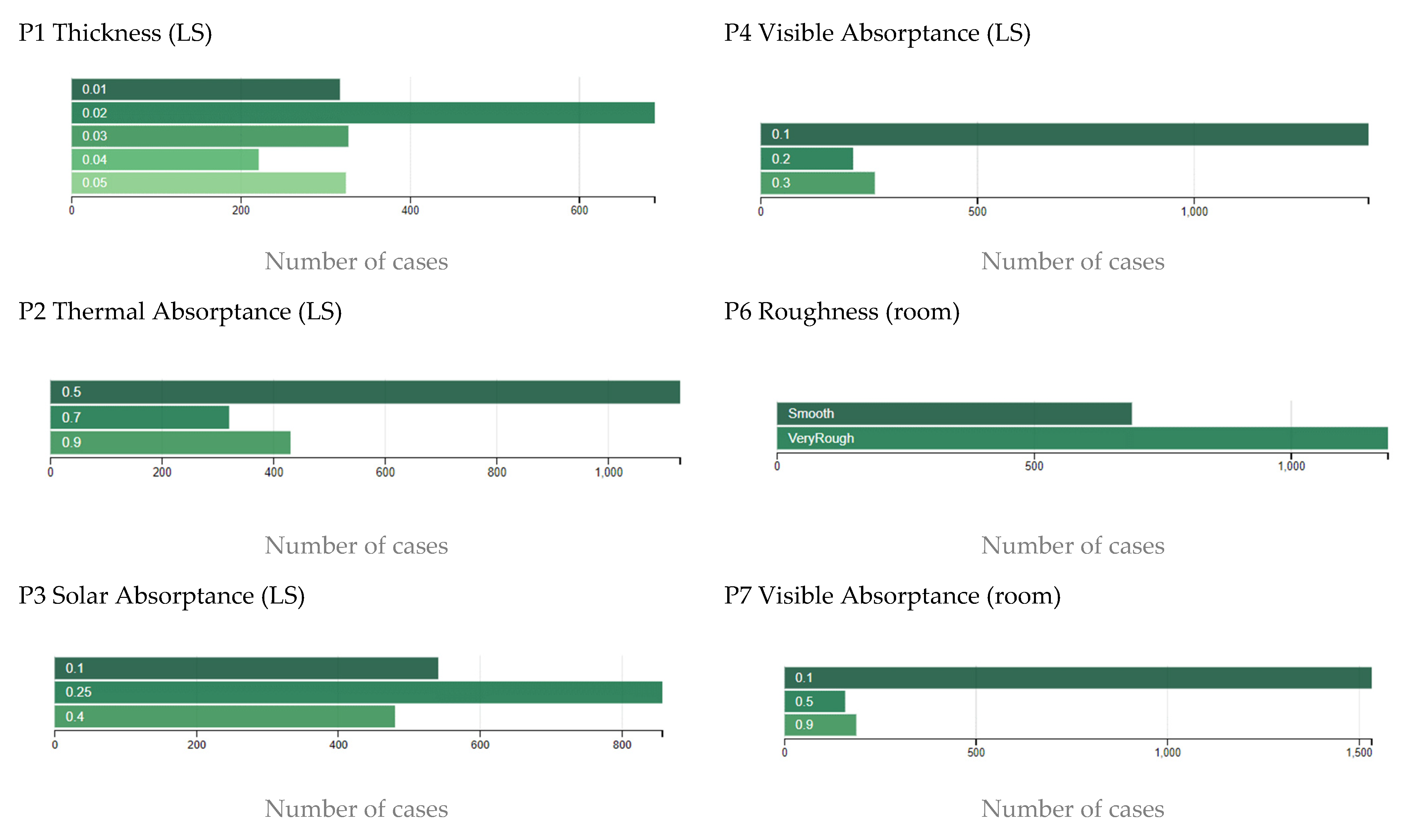
Finally, the occurrence of the other parameters (P1, P2, P3, P4, P6, P7) are shown in
Figure 9. The most recurring thickness of the LS is 2 cm, with a thermal absorptance of 0.5. The most recurring solar absorptance is not the lower one (0.1) but 0.25, while the visible absorptance is the lower one (0.1). These finishing characteristics give the ability to reflect the solar and visible radiation incident on the LS, thus the possibility of maximizing the daylight and minimizing the lights’ electricity. For the room, very rough surfaces with visible absorptance equal to 0.1 are the most recurring, and thus are obtainable with clear paints. In this way, visible radiation reflected by the LS could be re-reflected from the room indoor surfaces.
Considering the WR, in
Figure 10, the occurrence of the geometry parameter (T) is shown. In this case, the most recurring solution (687 times) is the LS_out_5090-30. Additionally, in this exposure, it could depend on the shading effect of the external LS. The most commonly recurring LS material type is fibreboard with 400 kg/m
3 density and α = 2.35 × 10
−3 m
2/s (646 cases), followed by fibreboard ρ = 250 kg/m
3, as can be seen in
Figure 11a. There are a greater number of occurrences for the double Low-E glazing type (
Figure 11b), with 1016 occurrences.
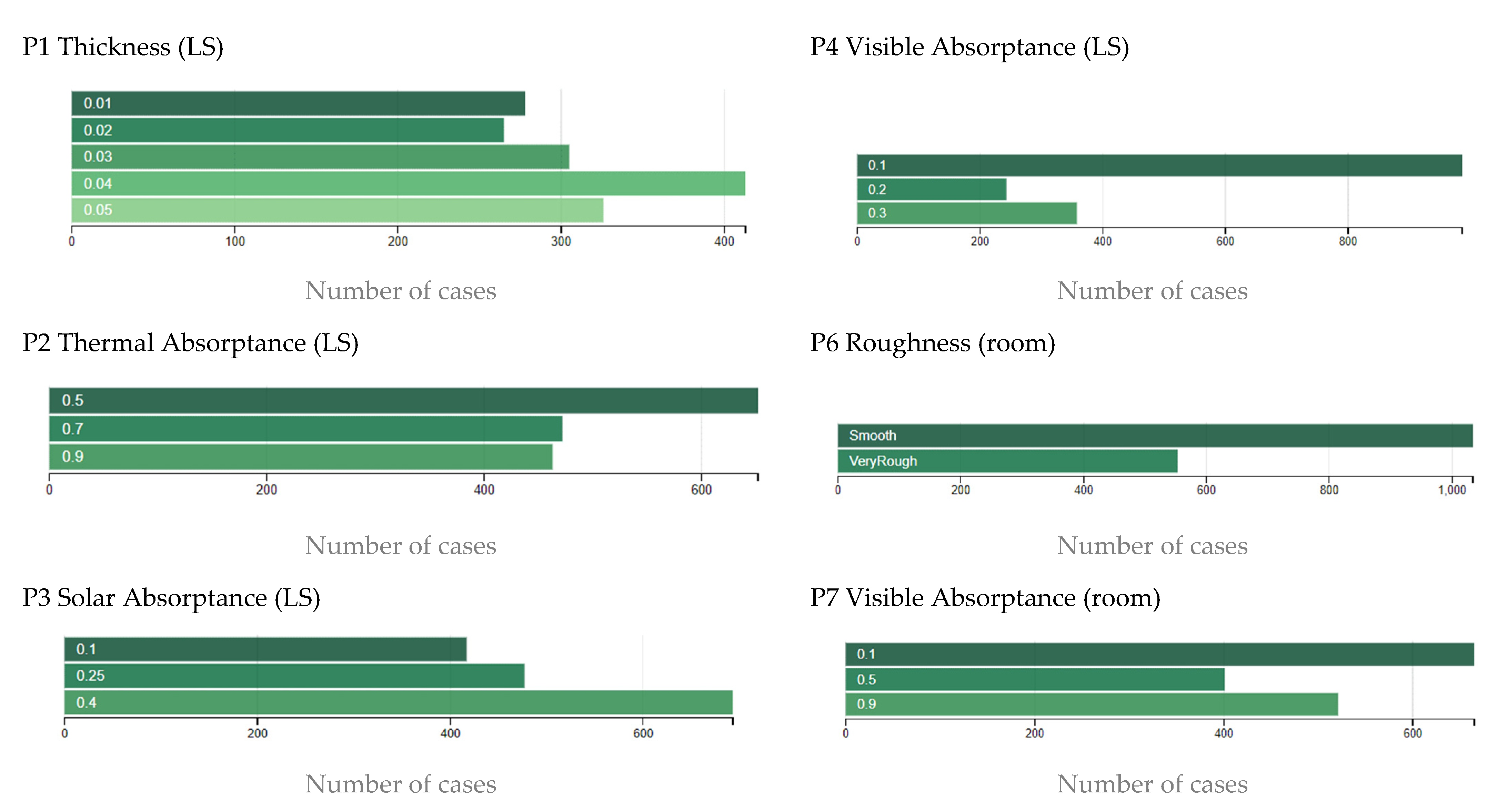
Considering the remaining parameters (P1, P2, P3, P4, P6, P7), their occurrences are shown in
Figure 12. The most recurring thickness of the LS is 4 cm, with a thermal absorptance of 0.5. In this case, the recurring visible absorptance is 0.1, while the solar absorptance is 0.4. As regards the room finishing surfaces, the case smooth is the most recurring, with visible absorptance equal to 0.1.
Some results for WR are opposites with respect the ER. The differences between the results obtained in the two rooms depends by the exposure. It should be emphasized that the ER is precisely exposed to the south-east, while the WR is exposed to the north-west. Moreover, as will be shown in the following section, some parameters, even if they are the most frequently recurring, are not those of the best solutions. Indeed, the combination of the most recurring parameters is not the optimal solution.
5.2. Optimal Solutions Analysis
In order to define the final solution, among the set of optimal ones, the designer could take several paths. One of them is to give priority to a specific goal, considered, for example, more important, thus minimizing or maximizing only one objective; however, it also satisfies others. In this case, let us analyse what happens. Among the feasible best solutions, in
Table 2 are shown the ones that maximize t0 and minimize t1, the identification codes of which are A1, A2, A3, and A4. First, it can be seen that some parameters are irrelevant for the determination of the best, such as P1 (LS Thickness) and P2 (LS Thermal Abs.), while other ones, e.g., T, P4, and P5 (Geometry, LS Visible Abs., and Window) must be uniquely determined to find the best. In this way, it could be most easy for the designer to choose a unique solution suitable for all objectives analysed.
Considering the ER, the main differences between A1 and A2 are given by the geometry; in fact, to maximize daylight, it is preferable to use a slightly protruding and inclined LS, while for minimizing the cooling need, the deepest and horizontal LS possible is better. In addition, another difference is given by the type of window glass (Double Float against the Triple Reflective), while the type of internal finishing it is similar. The visual result of the A1 solution is shown in
Figure 13. It is evident that, if t0 reaches the maximum value, the t1 will have a medium-high value (around 1232 kWh/year), while in
Figure 14, the numerical value of the A2 solution can be seen, showing how it is reached the minimum for t1, but not the maximum for t0. For both A1 and A2 solutions, the discomfort hours (s1) are lower than the constraint-imposed values (4137 h and 4187 h, respectively). In fact, the set of the constraint (s1) determines, for instance, that the solution in
Figure 14 does not reach the absolute minimum value for t1. Moreover, regarding the room finishing, this parameter is not influential in the case of cooling minimization, and a rough surface is preferred the in the case of daylighting maximization. This because the diffuse reflections given by a rough surface could help increase the daylighting in the whole working plane and not only in one specific point. Finally, it is evident that the combination of the parameters of the best solution are not all the most recurring parameters seen in the previous section. This because, on one hand, some parameters are irrelevant in helping to identify the best. On the other hand, since we are analysing the results of an optimization with a genetics algorithm, before identifying the pareto front, the algorithm develops several tries; thus, the combination of the most recurring parameters may not necessarily be the optimal solution.
In
Figure 15, which shows the solution A3, it can be seen that, in order to respect s1, t0 is not the absolute maximum, while
Figure 16 shows that, for the solution A4, t1 is not the absolute minimum.
It is evident that, also considering this type of design criteria (the minimization or maximization of one objective), the solutions obtained in some cases are completely opposite. Another way could be to choose the best solution only based on the minimization of the constraint s1. The results are show in
Table 3.
In addition, a comparison between the optimal solution and the existing case in terms of energy saving and daylighting improvement has been developed. For instance, in the ER, the application of A5 solution could bring an increase in daylighting level over the whole year of 59%, with a small increase in cooling need (+1%). This means the cooling need is recurring in other LS applications. For instance, Kontadakis et al. [
31] observed an increase in energy cooling consumption by 19% and 15% in an office with the same latitude of the present study. In fact, in the northern hemisphere, the tilt of a light shelf can improve the penetration of daylight in the room, but it can increase the cooling load at the same time [
9,
32]. It should also stress that the improvement in daylighting level brings a reduction in electricity for lighting (in this case, about −10%). Therefore, our results seem promising with respect to the existing literature.
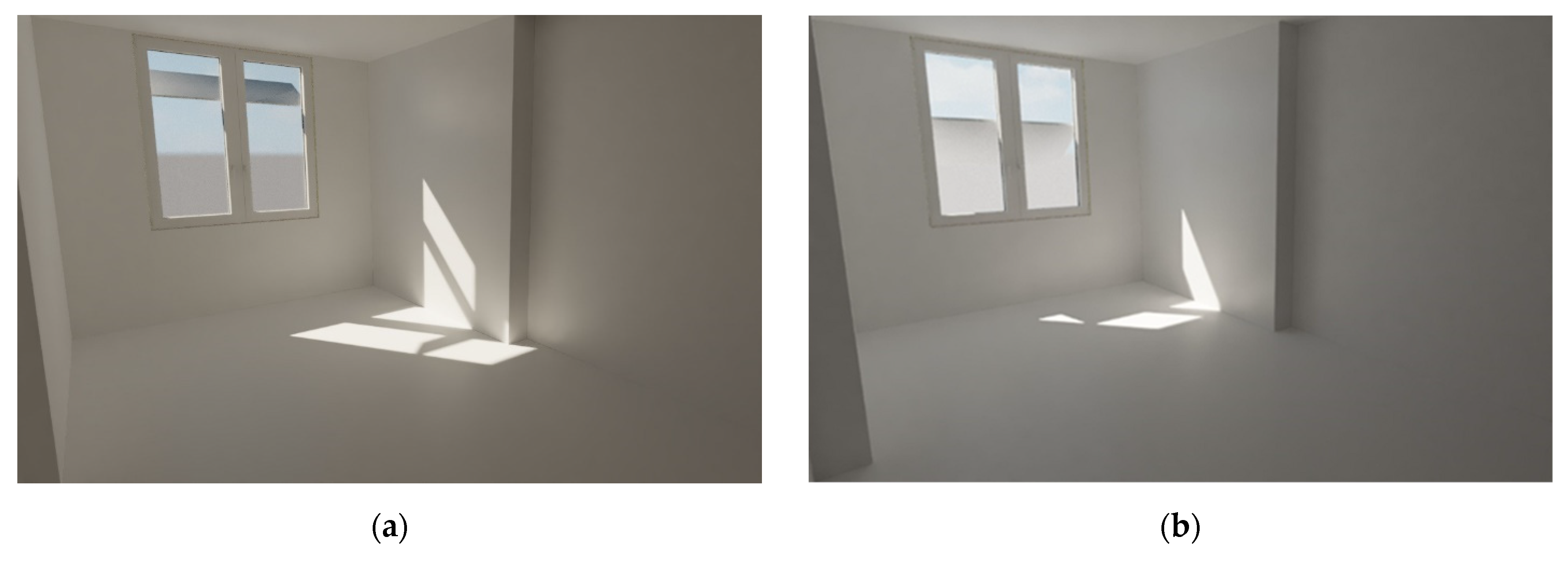
6. Architectural and Daylighting Aspects by Means of BIM
As last step of the method developed, the final architectural aspect of the solutions found was developed in Revit engine. For instance, the solutions that maximize the daylighting were chosen; thus, A1 for ER and A3 for the WR, as shown in
Figure 17a,b, respectively. From the literature review emerged that the most reliable software for simulating daylight are Radiance [
9,
10] and EnergyPlus [
7]. In this study, the daylighting calculation and optimal results were developed in EnergyPlus engine. It uses the SplitFlux method [
25] in conjunction with thermal analysis in order to develop daylight analysis and determine site conditions and solar gain and glare. Moreover, to obtain a quick render view of the possible illumination levels in the real space, Revit (illuminance renderings tool) was used. The choice to use Revit was based on the fact that the authors wanted to develop a circular method that started and ended with only one BIM engine (
Figure 1).
Moreover, it should be stressed that the architectural model used in this paper, developed in Revit, was validated considering a composite point cloud from a laser-scanner survey, as further explained in a previous study of the authors [
23]. In addition, the thermal model used in the EnergyPlus engine has been calibrated according to the approach defined by the M&V Guidelines [
33]. In fact, a comparison between the energy consumption measure and simulation has been carried out. The error in the annual energy consumption, the mean bias error, and the coefficient of variation of the root mean squared error are: −0.9%, +3.5% and +5.6%, respectively. These values are within the tolerance level defined by M&V Guideline.
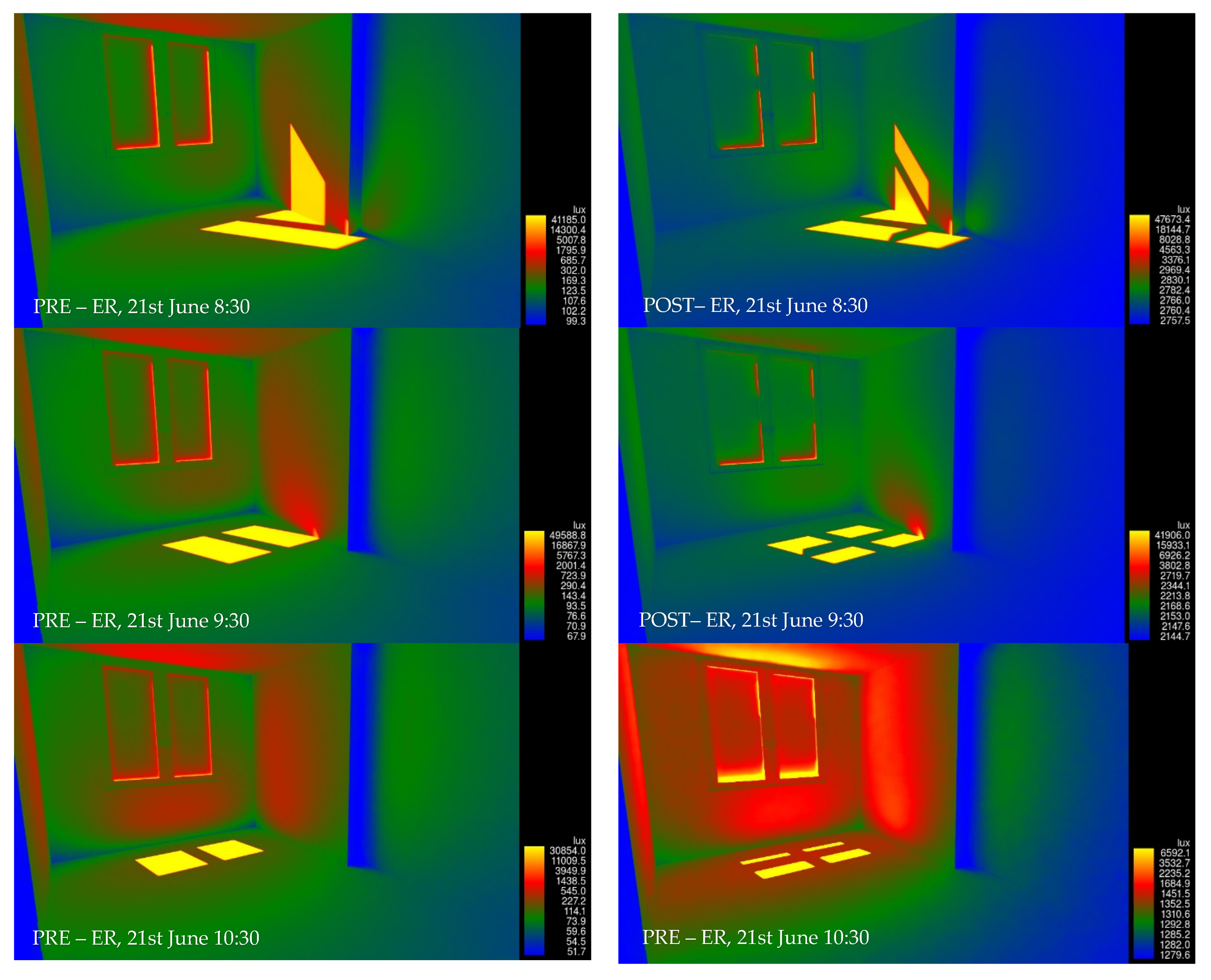
Since, in Revit, it is possible to carry out daylight simulation, the image of lux distribution on the inner room surfaces is reported for different hours of 21 June (the summer solstice). The optimization simulations were run for the whole year by means of an hourly weather file. In order to show some visual results in Revit, a representative summer day (the solstice one) was taken into account, as also done in other studies concerning LSs [
14,
31,
34].
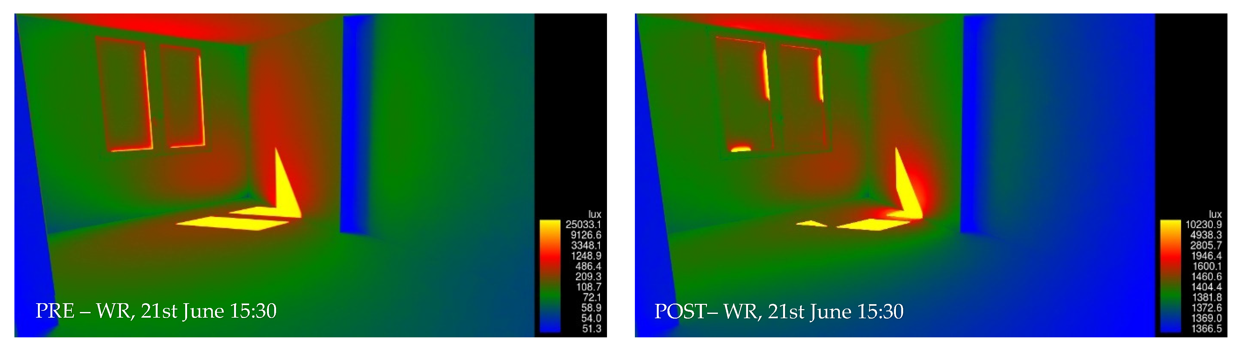
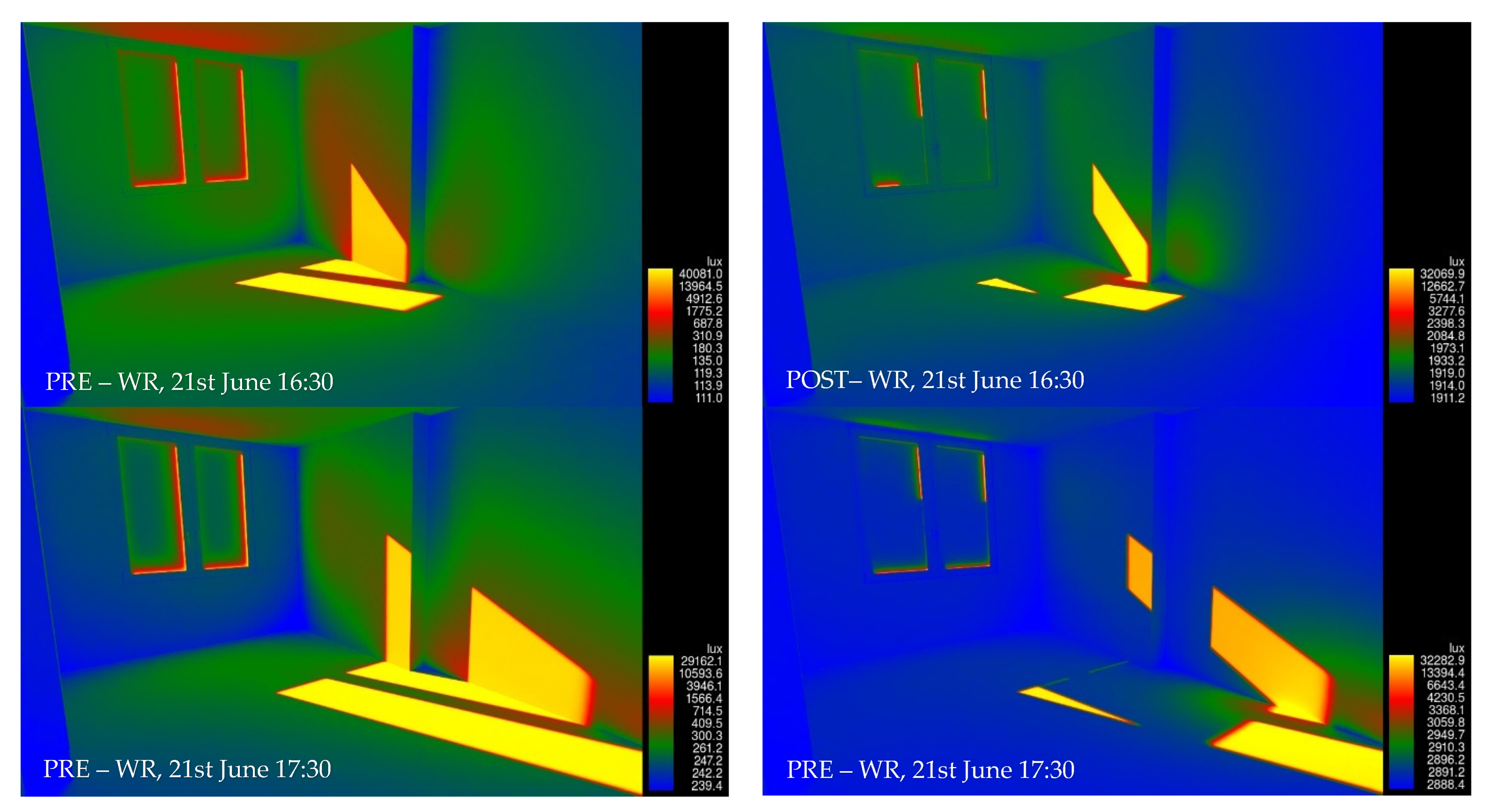
Figure 18 depicts the room layout in the case without LS (PRE) and in the case with LS (POST) for the ER. Note that the chromatic scale does not have the same minimum and maximum values. First of all, it can be seen how the illuminance level in the room with LS is more homogeneous, without too many variations between the areas with direct light and those in shadows. It is evident that the presence of LSs (in their configuration called A1) could really increase, between 25 to 32 times, the illuminance level in the back side of the room with respect the case without LS. On the other hand, the zones with possible glare (yellow areas) increase the lux value only by about one or two times. Similar comment could be written for the WR (
Figure 19).
So, the developed configurations of LS, the result of a constrained multi-objective optimization, can really improve the daylighting illuminance level in the rooms of the dormitory, reducing, on one hand, the electricity for artificial lights, and improving the visual comfort of the students.
It is challenging to control the penetration of the sun in morning and evening periods with the selection of orientation (east and west), particularly in the winter season, where the sun latitude is very low. However, since it is an existing building, we could not change the orientation. In fact, a parametric analysis, even when it changes, should be performed to give more complete results. Moreover, in the analysis, only the cooling season for the energy demand has been taken into account. A further development of the study could be to consider also, as an objective function, the minimization of the total heating need.
Finally, since this study is an optimization, which involves a large number of parameters and almost all possible geometries for the LS, it could easily be applied in other climatic contexts and find the best solution there. In this case, the only change should be the input hourly weather file. Indeed, in it, there are not only climatic parameters such as air temperature and humidity and wind speed and direction, but also global/direct/diffuse horizontal illuminance, zenith illuminance, total sky cover, and ceiling height. In addition, it should be stressed that hourly weather files are available for most locations in the world, and they can be freely download on the software website. Thus, the developed design process could be easily be repeated for other climates, e.g., northern ones.
7. Conclusions
The developed study has two main novelty points. First of all, a new methodological approach has been carried out, in which the BIM is the starting and ending point, with EnergyPlus used as energy dynamic simulation and jEPlus+EA for a multi-objective optimisation process. In this way, it is possible to check all building features in one 3D model and to evaluate some parameters such as daylight and so on. The method provides a previous calibration phase of the numerical model and an interactive output of the optimization. The whole process is described with a workflow developed by the authors, which has easy replicability for other case studies.
The second novelty is the deep investigation of light shelves’ (LSs) application in a refurbished building analysis, as part of circular and sustainable renovation processes. Considering two representative rooms of the refurbished building (on the east and west exposures), the whole window–LS–ceiling system has been analysed. The LSs’ geometry (position, height, width, inclination angle, and thickness) materials (wood, plastic, metal, and glass) and finishing type, as well as the windows’ glazing type and room interior context, have been changed, for a total of 2,843,100 configurations simulated. The results showed that:
The most recurring configuration in the feasible solutions is the external LS with the highest position, both for the west and east exposure, while the minimum recurring one are the internal LS. This is because, among the two objectives (maximizing daylighting, minimizing the cooling need), there is the minimization of the cooling need, and since the external LSs in the simulation are modelled as a shading surface, they are to be preferred.
The set of the best solutions (pareto front) does not contemplate all the most recurring parameters of the feasible solutions simulated. This because, even if one parameter could bring a suitable result in terms of objectives, their combination does not allow the same effect.
In order to find only one solution, the design criteria of the minimization or maximization of one objective could bring a completely opposite solution. So, a better way could be to choose the best solution only based on the minimization of one constraint: the number of hours of discomfort.
With this last criterion, the best solution for the east room is the outdoor LS 90 cm width, +15° inclined, in aluminium with 0.02 m of thickness, a solar absorptance equal to 0.25, and a visible absorptance equal to 0.1. In addition to a double float window and room internal surfaces with visible absorptance of 0.1, the daylighting illuminance levels is equal to 757.3 lux, and the total cooling need is 1194.9 kWh/year. In the west exposure, the best solution found is the outdoor LS, 90 cm width, with −30° of inclination. In this case, all materials analysed are suitable with a thickness of 0.01÷0.05 m, a solar absorptance of 0.4, and a visible absorptance of 0.1. The coupling with a double Low-E glass window and a room visible absorptance of 0.1 could bring a daylighting illuminance level equal to 221.5 lux and a total cooling need of 877.5 kWh/year.
The comparison between the optimal solution and the existing case in terms of energy saving and daylighting improvement shows, in the ER, an increase in daylighting level of +59%, with a small increase in cooling need (+1%). These results are promising with respect to the existing literature.
Compared with the existing case (without LS), the solutions that maximize only daylight show more homogeneous illuminance levels in the room, without variations between the areas in direct light and those in shadows. The presence of LSs could notably increase, between 25 to 32 times, the illuminance level in the back side of the room.
The developed LS configurations, the result of a constrained multi-objective optimization, can really improve the daylighting illuminance level in the rooms of the dormitory, reducing, on one hand the electricity for artificial lights and improving the visual comfort of the students.


 ,
, 


