
Use of Heat Pumps in the Hydrogen Production Cycle at Thermal Power Plants

 ,
,  , , , and
Abstract
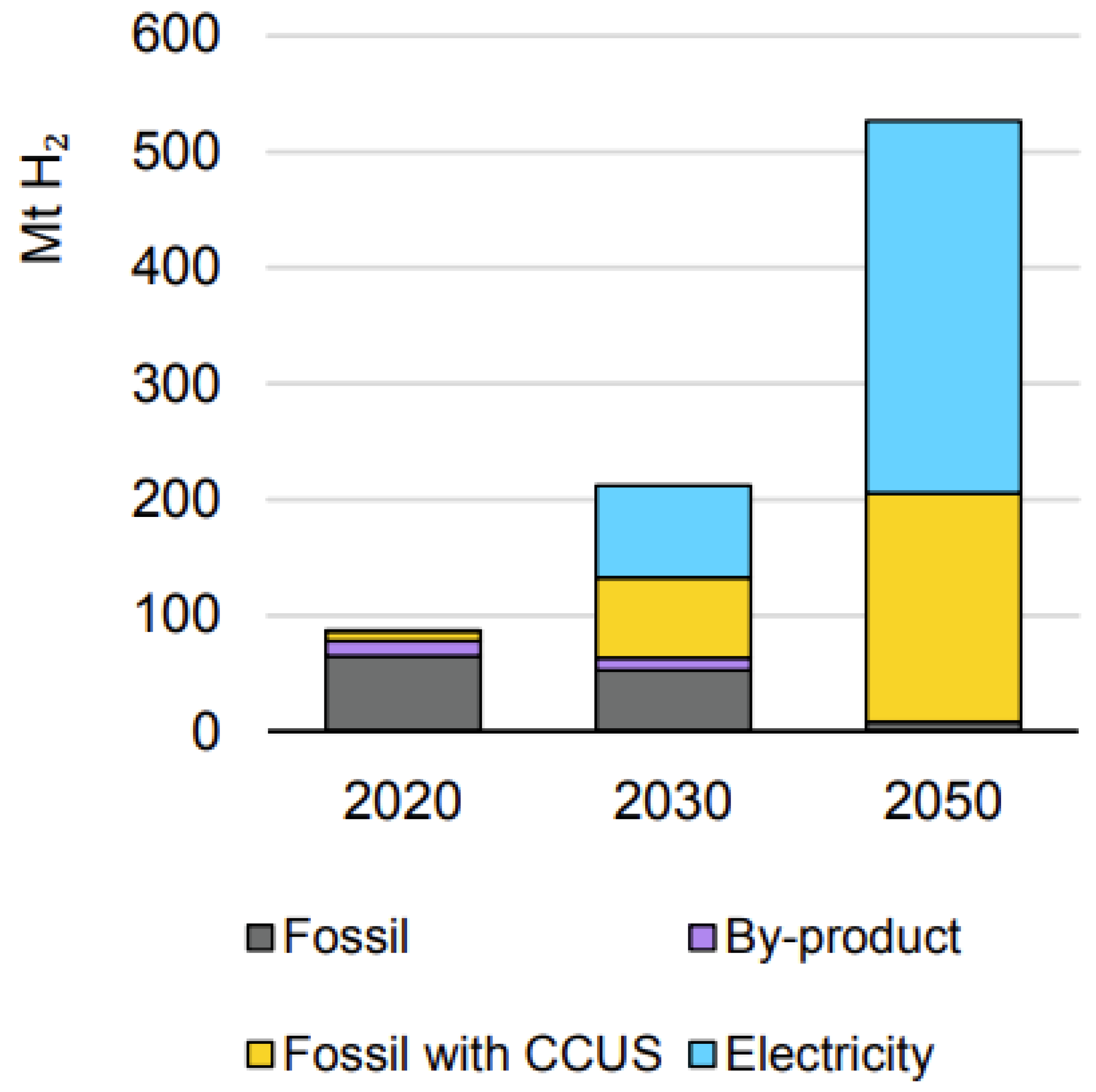
:1. Introduction
- Development and research of schemes for transferring real thermal power plants to a trigeneration cycle with the production of a new product—hydrogen—by the method of methane steam reforming;
- Increasing the efficiency of trigeneration plants by integrating a heat pump that uses waste heat from the power plant;
- Development of a methodology for determining the cost of fuel for the production of hydrogen in the trigeneration cycle of a thermal power plant.
- To develop a technological scheme for the production of hydrogen at TPPs;
- To propose a scheme for including HPUs in TPPs schemes to reduce the cost of hydrogen and reduce waste heat;
- To develop a methodology for determining fuel costs for hydrogen production in the cogeneration cycle of a thermal power plant.
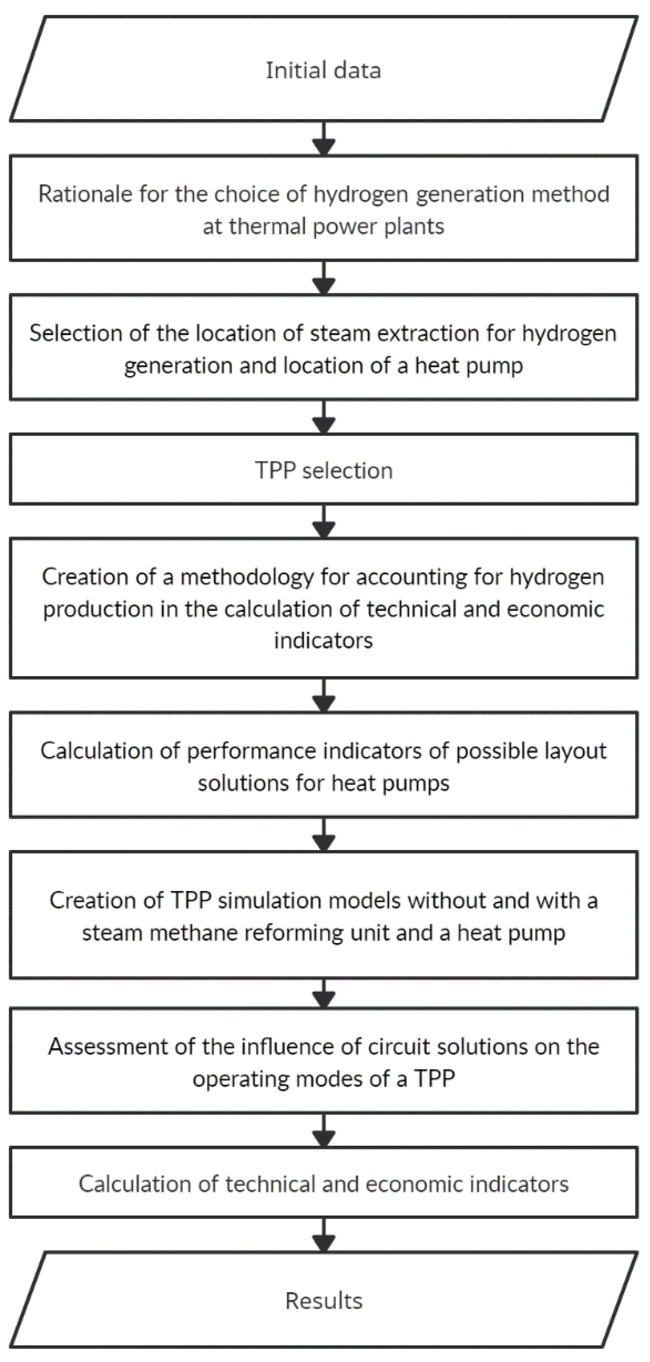
2. Materials and Methods
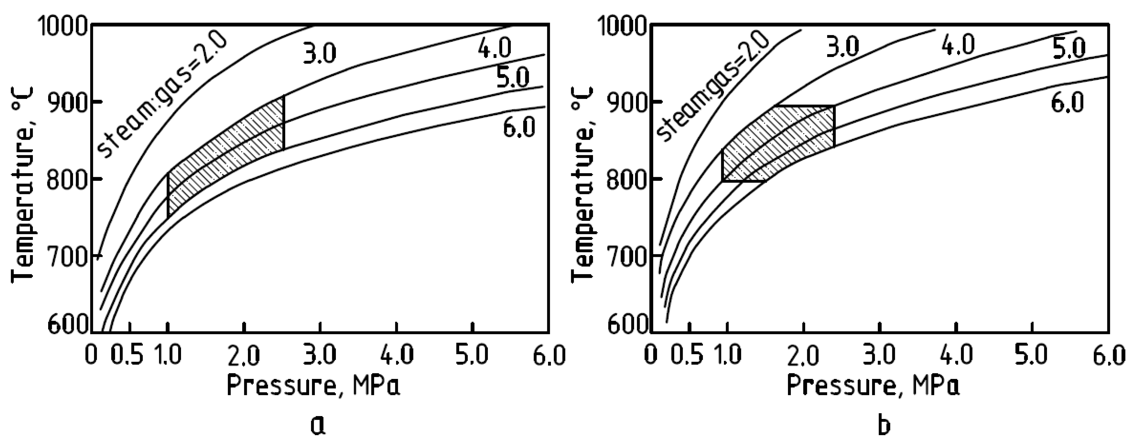
2.1. Substantiation of the Choice of Hydrogen Generation Method
- -
- Use of industrial extraction steam with a flow rate of 30 t/h;
- -
- Use of industrial extraction steam with a flow rate of 90 t/h;
- -
- Use of steam from the live steam collector with a flow rate of 30 t/h;
- -
- Use of steam from the live steam collector with a flow rate of 90 t/h.
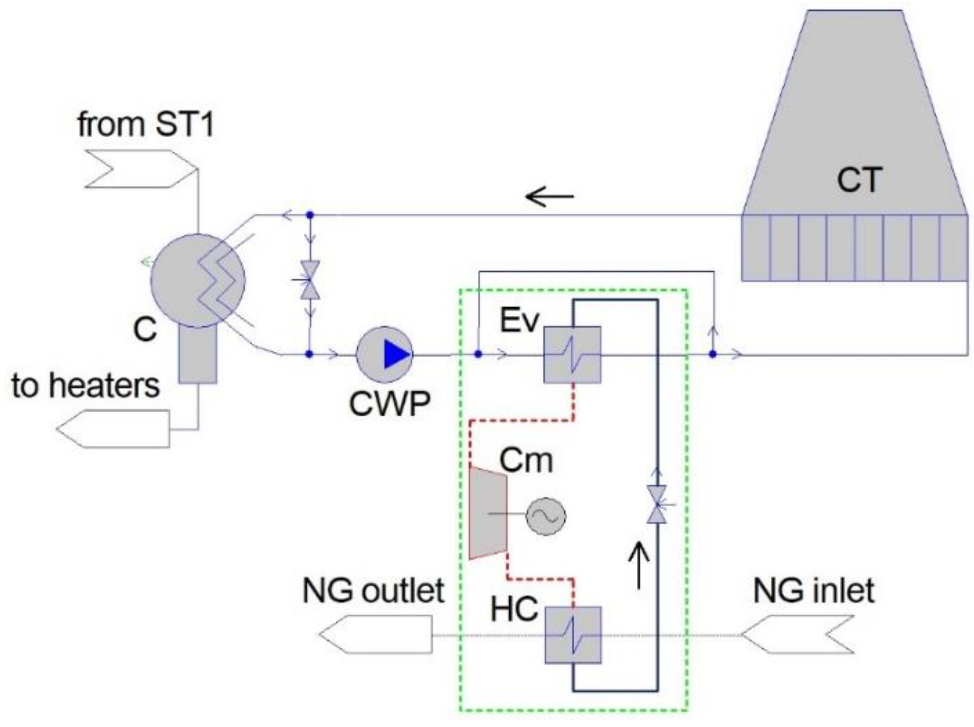
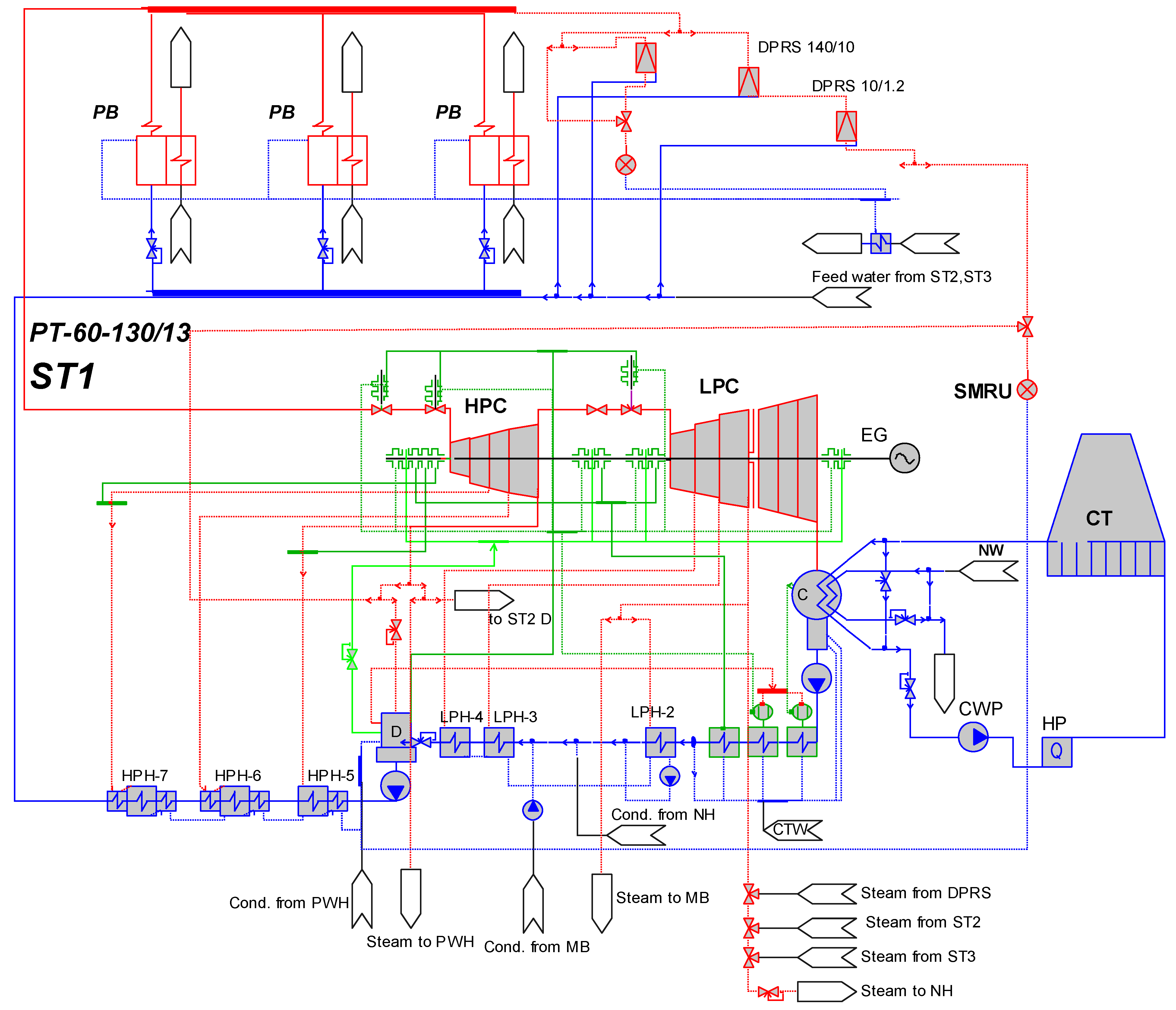
2.2. Schematic Solution for Integration of a Heat Pump
2.3. TPP Selection and Model Creation
- -
- CHPP has a live steam collector and production steam extraction;
- -
- The CHPP is located on the outskirts of Petrozavodsk, and, as a result, has the opportunity to expand the territory for new constructions;
- -
- The coefficient of utilization of installed capacity of the Petrozavodskaya CHPP in 2020 was 44.2%, in 2019—51.0%.
- Level of detailing for a heat-flow diagram of a simulated object is high;
- Models of equipment elements have been debugged and adjusted during many years of operation;
- Calculation accuracy of material and heat balance is high (10−6);
- There are several stages of testing at each step of model construction, calculation, and the analysis of calculation results;
- Graphical environment of the software is well developed; the results are visual.
- Creation of a mathematical model of an object, or design of a scheme;
- Parameterization of the mathematical model of the object, i.e., setting the parameters of the environment and the characteristics of the equipment for calculating the base case;
- Setting the operating mode of the object by entering the mode parameters.
2.4. Model Adequacy
2.5. Accounting for Hydrogen Production When Calculating Technical and Economic Indicators
3. Results and Discussions
4. Conclusions
- Using the example of a real thermal power plant, schemes have been developed and studied that allow switching cogeneration plants to a trigeneration mode with hydrogen production by integrating a methane steam reformer.
- To optimize the hydrogen production cycle, it is proposed to use heat pumps for preheating natural gas before the methane steam reformer.
- The use of a heat pump for the purpose of heating natural gas before MSRU does not have a significant impact on the operating modes of the combined heat and power plant due to its low power (1.47 MW). HPU efficiency indicator—the energy conversion factor—is low due to the large temperature difference between the LPHS (up to 27 °C) and the gas temperature at HPU outlet (95 °C). The use of a heat pump of a simple scheme for heating natural gas from a temperature of 15 °C to 95 °C saves only 0.16 thousand m3/h of natural gas. There is a need for additional research on the optimization of cycles and the consideration of other circuit solutions for heat pumps for joint operation with MSRU.
- A new methodology was developed for the distribution of fuel consumption in the production of a new product—hydrogen—at thermal power plants. This method can be adapted for use at various types of power plants.
- The minimum specific fuel consumption for hydrogen production—7.854 t ref.f./t H2—is achieved in the mode with steam extraction to MSRU from the turbine PT-60-130/13 (industrial extraction with a flow rate of 30 t/h). At this mode, the coefficient of fuel heat utilization is the highest among all modes with hydrogen production—66.18%, which is 2.3% lower than in the scheme without the use of MSRU. This is explained by the increase in the cost of electricity for own needs to ensure the operation of MSRU and HPU (7.39 MW).
Author Contributions
Funding
Institutional Review Board Statement
Informed Consent Statement
Data Availability Statement
Conflicts of Interest
Nomenclature
| Abbreviations | |
| APCS | automated process control system |
| C | steam turbine condenser |
| CCUS | carbon capture, utilization, and storage |
| CFHU | coefficient of fuel heat utilization |
| CHPP | combined heat and power plant |
| Cm | HPU compressor |
| CT | cooling tower of the circulating water supply system |
| CWP | cooling water pump |
| D | deaerator |
| DRPS | desuperheating and pressure reducing system |
| EG | electric generator |
| Ev | evaporator |
| HC | HPU condenser |
| HPC | high-pressure turbine cylinder |
| HPH | high-pressure heater |
| HPU | heat pump unit |
| LPC | low-pressure turbine cylinder |
| LPH | low-pressure heater |
| LPHS | low-potential heat source |
| MB | main boiler |
| MSR | methane steam reforming |
| MSRU | methane steam reforming unit |
| NG | natural gas |
| NH | network heater |
| PB | power boiler |
| PCHPP | the Petrozavodskaya CHPP |
| PWH | peaking water heater |
| RNW | return network water |
| ST | steam turbine |
| ST1 | turbine unit PT-60-130/13 st. №1 |
| TPP | thermal power plant |
| UC | “United Cycle” |
| VCHP | vapor compression heat pump |
| Variables and Coefficients | |
| Q0Σ | total heat output of steam boilers, MW |
| QN | steam energy for electricity generation, MW |
| Qind | steam energy for industrial steam extraction, MW |
| Qh | steam energy for heat generation, MW |
| BN | reference fuel consumption for electricity generation t ref.f./h |
| Bref.f.Σ | reference fuel consumption at a CCHP, t ref.f./h |
| Bind | reference fuel consumption for industrial steam generation t ref.f./h |
| Bh | reference fuel consumption for heat generation t ref.f./h |
| ΣN | power generation, MW |
| ΣNON | electricity for own needs, MW |
| QindON | industrial steam extraction for own needs, MW |
| QhON | heat for own needs, MW |
| bN | specific fuel consumption for electricity release, t ref.f./h |
| bind | specific fuel consumption for industrial steam extraction release, t ref.f./h |
| bh | specific fuel consumption for heat release, t ref.f./h |
| BΣH2 | consumption of reference fuel for hydrogen production, t ref.f./h |
| α | fraction of industrial steam extraction used for hydrogen production |
| QindST1 | heat load of industrial steam extraction of ST1, MW |
| Bref.f.ST1 | reference fuel consumption for industrial extraction, t ref.f./h |
| QoST1 | thermal power of the ST1 turbine unit, MW |
| Bref.f.MSRU | reference fuel consumption for the reaction implementation, t ref.f./h |
| Bref.f.furn | reference fuel consumption for the MSRU furnace, t ref.f./h |
| QH2 | thermal power of steam extracted for the MSRU needs, MW |
| bH2 | specific reference fuel consumption for steam supply at MSRU, t ref.f./t |
| GH2 | amount of produced hydrogen, t/h |
| ΣQNH | thermal load of network heaters, MW |
| ΣQBB | thermal load of built-in condenser bundle, MW |
| Qcv.H2n = 33.8 Gcal/t | net calorific value of hydrogen |
| 1.163 | the coefficient for converting Gcal/h to MW: 1.163 MW = 1 Gcal/h |
| Qcv.ref.f.n = 7 Gcal/t ref.f. | net calorific value of reference fuel |
References
- The Rio Declaration on Environment and Development. Available online: https://www.un.org/ru/documents/decl_conv/declarations/riodecl.shtml (accessed on 12 September 2021).
- The United Nations Framework Convention on Climate Change (UNFCCC). Available online: https://www.un.org/ru/documents/decl_conv/conventions/climate_framework_conv.shtml (accessed on 12 September 2021).
- The Kyoto Protocol. Available online: https://www.un.org/ru/documents/decl_conv/conventions/kyoto.shtml (accessed on 12 September 2021).
- The Paris Agreement. Available online: https://unfccc.int/files/meetings/paris_nov_2015/application/pdf/paris_agreement_russian_.pdf (accessed on 12 September 2021).
- A European Green Deal. Available online: https://ec.europa.eu/info/strategy/priorities-2019-2024/european-green-deal_en (accessed on 12 September 2021).
- EU Strategy on Energy System Integration. Available online: https://ec.europa.eu/energy/topics/energy-system-integration/eu-strategy-energy-system-integration_en (accessed on 19 September 2021).
- European Clean Hydrogen Alliance. Available online: https://ec.europa.eu/growth/industry/strategy/industrial-alliances/european-clean-hydrogen-alliance_en (accessed on 11 September 2021).
- Australia’s National Hydrogen Strategy. Available online: https://www.industry.gov.au/data-and-publications/australias-national-hydrogen-strategy (accessed on 15 September 2021).
- Russian Federal Law No. 296 on Limiting Greenhouse Gas Emissions. Available online: http://publication.pravo.gov.ru/Document/View/0001202107020031 (accessed on 12 September 2021).
- Vladimirov, I.A.; Mukhametova, L.; Yamashkin, M.V. Some Aspects of Use of Organic Containing Waste for Electrical and Thermal Energy Generation. In Proceedings of the High Speed Turbomachines And Electrical Drives Conference 2020 (HSTED-2020), Prague, Czech Republic, 14–15 May 2020; p. 1084. [Google Scholar] [CrossRef]
- Fomin, V.; Kalyutik, A. Combined-Cycle Gas Turbine Plant Based on Steam-Turbine Unit and a Parallel Superimposed Gas-turbine Plant with Waste Heat Recovery Boiler. In Proceedings of the International Scientific Electric Power Conference (ISEPC-2019), Saint Petersburg, Russia, 23–24 May 2019; p. 012139. [Google Scholar] [CrossRef] [Green Version]
- Sergeev, V.; Anikina, I.; Kalmykov, K. Using Heat Pumps to Improve the Efficiency of Combined-Cycle Gas Turbines. Energies 2021, 14, 2685. [Google Scholar] [CrossRef]
- Anikina, I.D.; Sergeyev, V.V.; Amosov, N.T.; Luchko, M.G. Use of heat pumps in turbogenerator hydrogen cooling systems at thermal power plant. Int. J. Hydrogen Energy 2017, 42, 636–642. [Google Scholar] [CrossRef]
- Sergeyev, V.V.; Anikina, I.D.; Kalmykov, K.S.; Naletov, I.D. Efficiency of Using Heat Pumps with Various Refrigerants in Real Steam Turbine Power Units with PT-80 and T-250 Turbines. In Proceedings of the International Scientific Conference on Energy, Environmental and Construction Engineering (EECE-2019), Saint Petersburg, Russia, 19–20 November 2019; Volume 140, p. 10001. [Google Scholar] [CrossRef] [Green Version]
- Cao, L.; Yu, I. Biorenewable hydrogen production through biomass gasification: A review and future prospects. Environ. Res. 2020, 186, 109547. [Google Scholar] [CrossRef] [PubMed]
- IEA. Global Hydrogen Review 2021; IEA: Paris, France, 2021; Available online: https://www.iea.org/reports/global-hydrogen-review-2021 (accessed on 20 September 2021).
- Chicco, G.; Mancarella, P. Distributed multigeneration: A comprehensive view. Renew. Sustain. Energy Rev. 2009, 13, 535–551. [Google Scholar] [CrossRef]
- Mancarella, P. MES (multi-energy systems): An overview of concepts and evaluation models. Energy 2014, 65, 1–17. [Google Scholar] [CrossRef]
- Jana, K.; Ray, A.; Majoumerd, M.M.; Assadi, M.; De, S. Polygeneration as a future sustainable energy solution—A comprehensive review. Appl. Energy 2017, 202, 88–111. [Google Scholar] [CrossRef]
- Tuvalbaev, B.G.; Moiseev, V.I. Operation of TPPs in a constant mode with the production of additional products on unclaimed energy. Energy Save Water Treat. 2013, 4, 24–27. [Google Scholar]
- Tuvalbaev, B.G.; Marchenko, M.E.; Marchenko, E.M.; Valitov, D.S. Conceptual directions of development of heat power engineering. Energy Save Water Prep. 2017, 3, 3–9. [Google Scholar]
- Decree of the Government of the Russian Federation No. 2162-r Dated August 5, 2021 on Approval of the Concept of Development of Hydrogen Energy in the Russian Federation. Available online: http://government.ru/docs/42971/ (accessed on 15 October 2021).
- Decree of the President of the Russian Federation No. 208 Dated May 13, 2017 on the Approval of the Economic Security Strategy of the Russian Federation for the Period up to 2030. Available online: http://www.kremlin.ru/acts/bank/41921 (accessed on 12 September 2021).
- Decree of the Government of the Russian Federation No. 1523-r Dated June 9, 2020 on the Approval of the Energy Strategy of the Russian Federation for the Period up to 2035. Available online: https://docs.cntd.ru/document/565068231 (accessed on 12 September 2021).
- Decree of the President of the Russian Federation No. 176 Dated April 19, 2017 on the Strategy of Environmental Safety of the Russian Federation for the Period up to 2025. Available online: http://government.ru/docs/all/111285/ (accessed on 15 October 2021).
- Balasubramanian, B.; Ortiz, A.L.; Kaytakoglu, S.; Harrison, D.P. Hydrogen from methane in a single-step process. Chem. Eng. Sci. 1999, 54, 3543–3552. [Google Scholar] [CrossRef]
- Abbas, H.F.; Daud, W.M.A.W. Hydrogen production by methane decomposition: A review. Int. J. Hydrogen Energy 2010, 35, 1160–1190. [Google Scholar] [CrossRef]
- Carapellucci, R.; Giordano, L. Upgrading existing gas-steam combined cycle power plants through steam injection and methane steam reforming. Energy 2019, 173, 229–243. [Google Scholar] [CrossRef]
- Romano, M.C.; Cassotti, E.N.; Chiesa, P.; Meyer, J.; Mastin, J. Application of the Sorption Enhanced-Steam Reforming process in combined cycle-based power plants. Energy Procedia 2011, 4, 1125–1132. [Google Scholar] [CrossRef] [Green Version]
- Guo, L.; Ding, Y.; Liao, Q.; Zhu, X.; Wang, H. A new heat supply strategy for CO2 capture process based on the heat recovery from turbine exhaust steam in a coal-fired power plant. Energy 2022, 239, 121817. [Google Scholar] [CrossRef]
- Zhang, H.; Liu, Y.; Liu, X.; Duan, C. Energy and exergy analysis of a new cogeneration system based on an organic Rankine cycle and absorption heat pump in the coal-fired power plant. Energy Convers. Manag. 2020, 223, 113293. [Google Scholar] [CrossRef]
- Zhang, H.S.; Zhao, H.B.; Li, Z.L. Performance analysis of the coal-fired power plant with combined heat and power (CHP) based on absorption heat pumps. J. Energy Inst. 2016, 89, 70–80. [Google Scholar] [CrossRef]
- Alimgazin, A.S.; Alimgazina, S.G.; Zhumagulov, M.G. Heat pump in a new modular configuration to recover low-grade heat emissions at enterprises. In Proceedings of the High Speed Turbomachines and Electrical Drives Conference 2020 (HSTED-2020), Prague, Czech Republic, 14–15 May 2020; Volume 178, p. 01003. [Google Scholar] [CrossRef]
- Alimgazin, A.S.; Prishchepova, S.A.; Sultanguzin, I.A. The use of heat transformers for the low-temperature secondary energy resources recovery in non-ferrous metallurgy enterprises. In Proceedings of the High Speed Turbomachines and Electrical Drives Conference 2020 (HSTED-2020), Prague, Czech Republic, 14–15 May 2020; Volume 178, p. 01017. [Google Scholar] [CrossRef]
- Zhang, H.S.; Zhao, H.B.; Li, Z.L.; Hu, E. Optimization Potentials for the Waste Heat Recovery of a Gas-steam Combined Cycle Power Plant Based on Absorption Heat Pump. J. Therm. Sci. 2019, 28, 283–293. [Google Scholar] [CrossRef]
- Vannoni, A.; Giugno, A.; Sorce, A. Integration of a flue gas condensing heat pump within a combined cycle: Thermodynamic, environmental and market assessment. Appl. Therm. Eng. 2021, 184, 116276. [Google Scholar] [CrossRef]
- Mendeleev, D.I.; Galitskii, Y.Y.; Marin, G.E.; Akhmetshin, A.R. Study of the work and efficiency improvement of combined-cycle gas turbine plants. In Proceedings of the International Scientific and Technical Conference Smart Energy Systems 2019 (SES-2019), Kazan, Russia, 18–20 September 2019; Volume 124, p. 05061. [Google Scholar] [CrossRef] [Green Version]
- Mendeleev, D.I.; Maryin, G.E.; Akhmetshin, A.R. Improving the efficiency of combined-cycle plant by cooling incoming air using absorption refrigerating machine. In Proceedings of the International Scientific Electric Power Conference, Saint Petersburg, Russia, 23–24 May 2019; Volume 643, p. 012099. [Google Scholar] [CrossRef]
- Steam Reforming of Methane—Hydrogen Production. Hydrogen Production in SMR. Available online: https://www.engineering-airliquide.com/ru/parovoj-riforming-metana-proizvodstvo-vodoroda (accessed on 20 September 2021).
- Pismen, M.K. Hydrogen Production in the Oil Refining Industry; Chemistry: Moscow, Russia, 1976. [Google Scholar]
- Romanov, S. “United Cycle” Software for Simulation of Flow Sheets of Power Plants. In Proceedings of the 16th International Conference on Efficiency, Cost, Optimization, Simulation, and Environmental Impact of Energy Systems (ECOS-2003), Copenhagen, Denmark, 30 June–2 July 2003; pp. 1691–1696. [Google Scholar]
- Romanov, S.N. Software “United Cycle” for Simulation of Static Operation Modes of Power Plants. In Proceedings of the International Society for Optical Engineering, St. Petersburg, Russia, 12–17 June 2001; pp. 306–309. [Google Scholar] [CrossRef]
- Decree of the Representatives of the Russian Federation of October 22, 2012 N 1075 (as amended on 20 May 2022) on Pricing in the Field of Heat Supply. Available online: https://docs.cntd.ru/document/902148460 (accessed on 6 June 2022).
- Kolbantseva, D.; Treschev, D.; Trescheva, M.; Anikina, I.; Kolbantsev, Y.; Kalmykov, K.; Aleshina, A.; Kalyutik, A.; Vladimirov, I. Analysis of Technologies for Hydrogen Consumption, Transition and Storage at Operating Thermal Power Plants. Energies 2022, 15, 3671. [Google Scholar] [CrossRef]


| Parameter | APCS | UC | Note |
|---|---|---|---|
| Power, MW | 51.0 | 51.0 | Data are identical |
| Live steam consumption, t/h | 264.0 | 255.9 | The difference is 3.0% |
| Live steam temperature, °C | 544.0 | 545.9 | The difference is 0.3% |
| Live steam pressure, kgf/cm2 | 122.0 | 122.0 | Data are identical |
| Steam pressure in the industrial extraction chamber, kgf/cm2 | 12.6 | 12.6 | Data are identical |
| Pressure in the condenser, kgf/cm2 | 0.103 | 0.103 | Data are identical |
| Feed water temperature behind HPH-5, °C | 189.0 | 185.0 | The difference is 2.1% |
| Feed water temperature behind HPH-6, °C | 215.0 | 210.7 | The difference is 2.0% |
| Feed water temperature behind HPH-7, °C | 243.0 | 236.4 | The difference is 2.7% According to the documentation, the temperature of the feed water at the steam flow to the turbine is about 239 °C. Thus, the temperature at the outlet of the heaters of the HPH group is 2.3% higher than the calculated value. |
| Feed water consumption, t/h | 260.0 | 260.0 | Data are identical |
| Condensate temperature in the condenser, °C | 50.0 | 46.0 | The saturation temperature at the pressure in the condenser corresponds to a temperature of 46 °C. |
| Condensate temperature behind LPH-4, °C | 117.0 | 117.0 | Data are identical |
| Parameter | Value | |||
|---|---|---|---|---|
| Operating Mode | Industrial Steam Extraction | Steam Extraction from the Collector | ||
| Steam extraction to MSRU, t/h | 30 | 90 | 30 | 90 |
| Extracted steam temperature, °C | 285.6 | 275.6 | 494.3 | 494.2 |
| Power underproduction factor, — | 0.61 | 0.58 | 1 | 1 |
| Reduced fuel consumption due to higher temperature of extracted steam, thousand m3/h | 0.21 | 0.56 | 0.61 | 1.83 |
| Temperature of LPHS before HPU, °C | 27.0 | 24.5 | 27.9 | 27.0 |
| Temperature of LPHS after HPU, °C | 18.0 | |||
| Methane consumption, t/h | 28.79 | |||
| Temperature of methane before HPU, °C | 15 | |||
| Temperature of methane after HPU, °C | 95 | |||
| HPU power, MW | 1.47 | |||
| Energy conversion factor of HPU, — | 1.53 | |||
| HPU compressor power usage, MW | 1.32 | |||
| LPHS consumption, t/h | 49.02 | 67.03 | 44.38 | 48.96 |
| Reduced fuel consumption due to HPU, thousand m3/h | 0.16 | |||
| Parameter | Value | ||||
|---|---|---|---|---|---|
| Operating Mode | Initial | Industrial Steam Extraction | Steam Extraction from the Collector | ||
| Steam extraction to MSRU, t/h | - | 30 | 90 | 30 | 90 |
| Electricity supply, MW | 231.84 | 224.45 | |||
| Total fuel consumption, t ref.f. | 106.20 | 157.55 | 161.12 | 158.68 | 163.58 |
| Change in total fuel consumption, % | - | 48.36 | 51.72 | 49.42 | 54.03 |
| Fuel consumption for heat supply, t ref.f. | 46.94 | 46.97 | 47.03 | 47.01 | 47.03 |
| Specific fuel consumption for heat supply, kg ref.f./MW | 130.61 | 130.70 | 130.86 | 130.80 | 130.86 |
| Change in specific fuel consumption for heat supply, % | - | 0.07 | 0.19 | 0.14 | 0.19 |
| Fuel consumption for electricity supply, t ref.f. | 59.26 | 57.62 | 55.04 | 58.68 | 57.40 |
| Specific fuel consumption for electricity supply, g ref.f./(kW h) | 255.60 | 256.73 | 245.21 | 261.46 | 255.72 |
| Change in specific fuel consumption for electricity supply, % | - | 0.44 | −4.06 | 2.29 | 0.05 |
| Fuel consumption for hydrogen supply, t ref.f. | - | 52.95 | 59.06 | 52.99 | 59.15 |
| Specific fuel consumption for hydrogen supply, t ref.f./t H2 | - | 7.854 | 8.759 | 7.858 | 8.773 |
| CFHU, % | 68.39 | 66.18 | 64.72 | 65.71 | 63.75 |
Publisher’s Note: MDPI stays neutral with regard to jurisdictional claims in published maps and institutional affiliations. |
© 2022 by the authors. Licensee MDPI, Basel, Switzerland. This article is an open access article distributed under the terms and conditions of the Creative Commons Attribution (CC BY) license (https://creativecommons.org/licenses/by/4.0/).
Share and Cite
Kalmykov, K.; Anikina, I.; Kolbantseva, D.; Trescheva, M.; Treschev, D.; Kalyutik, A.; Aleshina, A.; Vladimirov, I. Use of Heat Pumps in the Hydrogen Production Cycle at Thermal Power Plants. Sustainability 2022, 14, 7710. https://doi.org/10.3390/su14137710
Kalmykov K, Anikina I, Kolbantseva D, Trescheva M, Treschev D, Kalyutik A, Aleshina A, Vladimirov I. Use of Heat Pumps in the Hydrogen Production Cycle at Thermal Power Plants. Sustainability. 2022; 14(13):7710. https://doi.org/10.3390/su14137710
Chicago/Turabian StyleKalmykov, Konstantin, Irina Anikina, Daria Kolbantseva, Milana Trescheva, Dmitriy Treschev, Aleksandr Kalyutik, Alena Aleshina, and Iaroslav Vladimirov. 2022. "Use of Heat Pumps in the Hydrogen Production Cycle at Thermal Power Plants" Sustainability 14, no. 13: 7710. https://doi.org/10.3390/su14137710