Article

Research on Torsional Characteristic and Stiffness Reinforcement of Main Girder of Half-Through Truss Bridge

1
Key Laboratory of Concrete and Prestressed Concrete Structures of Ministry of Education, Southeast University, Nanjing 211189, China
2
School of Civil Engineering, Southeast University, Nanjing 211189, China
3
School of Mechanics and Civil Engineering, China University of Mining and Technology, Xuzhou 221116, China
*
Author to whom correspondence should be addressed.
Sustainability 2022, 14(11), 6628; https://doi.org/10.3390/su14116628
Submission received: 25 April 2022 / Revised: 24 May 2022 / Accepted: 25 May 2022 / Published: 28 May 2022

Abstract

:
The stronger stability of a half-through truss bridge can improve the bridge performance for resisting extreme loads, such as earthquakes and shock. To improve the bridge stability, it is necessary to improve the torsional stiffness of the half-through truss bridge. To study the torsional characteristics of the main girder of the half-through truss bridge, the half-through truss is equivalent to an open slot thin-walled member, and the calculation formula of the free torsional moment of inertia of the main girder is deduced. Because the main truss can resist warping deformation through bending, it has a great contribution to the torsional stiffness. Based on the vertical bending action of the main truss, the calculation formula of the correction of the torsional moment of inertia of the main girder is deduced. Taking a half-through truss pedestrian bridge as an example, the torsional moment of inertia of the bridge under different width-span ratios is calculated by theoretical and finite element analysis. The results show that when calculating the torsional moment of inertia of the main girder of the half-through truss bridge, the free torsional moment of inertia calculated by the equivalent open slot section is very different from the actual torsional stiffness, and the bending correction value must be considered. The theoretical solution after taking into account the corrected value is well-fitted with the finite element results. The theoretical formula can be used to explain the torsional mechanism of this kind of bridge. According to the mechanism research, the method of installing X-shaped longitudinal supports between the upper transverse girders to improve the torsional stiffness is finally formulated. Installing the X-shaped longitudinal supports not only can keep the size of the half-through truss bridge unchanged but can also have a considerable enhancement effect, which will significantly improve the torsional stiffness and stability of existing bridges.

1. Introduction

Because there is no horizontal connection between the top chords of half-through truss bridges, the upper parts of these bridges are not closed, and the height of the main trusses can be much lower than those of general truss bridges. Thus, half-through truss bridges are relatively lightweight and have no impact on the height of passing vehicles. Because of the smaller space occupation, this bridge type is widely used in railway bridges, port bridges, and military bridges. In recent years, to pursue both aesthetic effects and durability effects, half-through truss bridges made from an aluminum alloy are widely used in urban pedestrian bridges in worldwide [1,2,3]. Two long-span pedestrian bridges that are aluminum alloy half-through truss bridges are shown in Figure 1.
Figure 2 shows the elastic buckling mode of an aluminum alloy half-through truss pedestrian bridge, and the whole bridge shows significant torsional deformation. In the calculation theory of the elastic stability of the half-through truss bridge, the theoretical assumption is the ideal state in which the torsional deformation of the whole bridge will not be considered. Therefore, the critical buckling load in theory is generally greater than the actual value. We defined two parameters to further illustrate the characteristics of the half-through truss bridge. The theoretical buckling load is designated as F1, and the actual buckling load is designated as F2.
Taking the bridge shown in Figure 2 as an example, for this bridge, assuming that the theoretical buckling load factor F1 is 1, the actual calculation result F2 is only 0.53. We use F2/F1 to represent the stability performance of the structure. The closer this ratio (F2/F1) is to 1, the better the stability of the bridge.
Equal torque is applied in the middle of the bridge span, and the torsional stiffness can be measured by the torsional angle. We selected 14 existing half-through truss bridges and analyzed their torsional stiffness and stability by the finite element method. Normalizing the calculated values of torsional stiffness, the torsional stiffness is positively correlated with stability as shown in Figure 2 significantly.
Due to the narrow width of pedestrian bridges, the width-span ratio of long-span pedestrian bridges is usually small, resulting in the low torsional stiffness of half-through truss bridges. The low torsional stiffness will reduce the structural stability [4]. The insufficient stability of bridges will bring a negative impact on resisting earthquakes, shock, and other extreme loads [5,6]. Obviously, we should study how to enhance the torsional stiffness of the half-through truss bridge.
The mechanism model is interpretable and can enhance the reliability of structural analysis. Combined with finite element analysis, it is indispensable in structural engineering research. If the torsional mechanism of half-through truss bridges can be learned, we can formulate an efficient and reliable torsional stiffness strengthening method for aluminum alloy pedestrian bridges using half-through trusses. Therefore, the first step is to study the calculation method of the torsional moment of inertia of the section of the main girder of the half-through truss bridge.
Force method can be used to analyze the torsional stiffness of the truss structure, but this theoretical method is too complex for understanding the mechanism [7]. To solve the calculation of the moment of inertia of the truss girder, a single truss is equaled to a continuous thin wall with the same mechanical performance [8]. Therefore, the truss structure can be continuously equaled to a closed thin-walled member, and then the feature value of the section can be expediently calculated by using the thin-walled member theory. From the single truss girder [9,10,11] to the space truss [12,13,14] and the plate-truss composite girder bridge [15,16], the equivalent theory has been widely used. Theoretical values were confirmed to be reliable in the trial and finite element analyses of space trusses [17,18] and plate-truss composite girders [19,20].
To summarize, the equivalent theory and finite element model can obtain accurate torsional characteristic values of closed space truss girders, which have been applied in space trusses and plate-truss composite girder bridges. However, there is a lack of transverse supports between the upper chords of the half-through truss bridge, and the torsional characteristic of the half-through truss bridge is quite different from that of the general closed space truss, so the calculation theory of the general truss girder cannot be directly applied.
In this paper, the torsional moment of inertia of the half-through truss bridge is studied theoretically, so we can understand its torsional mechanism and then formulate the strengthening method of the torsional stiffness of this bridge according to the mechanism. Finally, pedestrian bridges made by aluminum alloy half-through trusses will not only have corrosion resistance, but they will also obtain better resistance to earthquakes, shock, and other extreme loads due to the increase in stability.

2. Equivalent Calculation of Torsional Moment of Inertia

2.1. Equivalent Model of Section of Main Girder

Figure 3 shows one segment of the half-through truss bridge. In Figure 3, c is the length of one plate of the main truss, b is the spacing of two main trusses (bridge width), H is the height of the vertical web (bridge height), a is the height of the vertical web above the transverse girder, and h is the height of the transverse girder. This is different with a general truss bridge or plate-truss composite beam bridge, as there is no lateral connection between the top chords of the half-through truss bridge. In each segment, the transverse girder connects the two main trusses on the right and left. The horizontal X-shaped frame is installed between the two lower chords, so the X-shaped frame and two lower chords also form a stable truss.
The transverse girder is equivalent to the vertical stiffener which has no torsional stiffness, so the section of the half-through truss bridge includes the horizontal X-shaped frame and two main trusses after ignoring the transverse girder. According to the equivalence principle, the main truss can be equivalent to a thin wall, and the bottom X-shaped frame as a truss structure can also be equivalent to a thin wall. Therefore, the section of the half-through truss bridge can be equivalent to the open thin-walled member. Figure 4 shows the section of the half-through truss bridge and its equivalent section of the thin-walled member. As shown in Figure 4, the thickness of the side wall is designated tz, and the thickness of the bottom wall is designated as tx. The two side walls and the bottom wall together form an open thin-walled member.
The research objects of the existing literature are the long-span space trusses and the plate truss composite girders of cable-stayed bridges. These objects have the following two characteristics: (1) The space trusses and the plate-truss composite girders are equivalent to closed thin-walled members. The closed area is large, and the chord size is too small compared with the closed area surrounded by trusses, so the chords have little effect on supporting the overall structure by resisting warpage. (2) The spans of the space trusses and the plate-truss composite girders are quite long, and the width-span ratio of these structures is quite large, so the control to spatial warpage by boundary constraints is weak for most structure segments.
Therefore, for the space trusses and plate-truss composite girders, the free torsional moment of inertia calculated by their equivalent closed thin-walled section is sufficient to represent the torsional stiffness of the structure. Thus, the calculation formula of the free torsional moment of inertia of the closed thin-walled member can be directly used in theoretical analysis for the space trusses and plate-truss composite girders. Referring to existing ideas, the warping deformation in restrained torsion is not considered here. J is the torsional moment of inertia of the equivalent section of the half-through truss bridge, and the formula for calculating J can refer to the formula for calculating the free torsional moment of inertia of the open groove thin-walled member theory [21] as follows:
J = 1.12 ( 2 H t z 3 + b t x 3 ) 3
where tz is the thickness of the equivalent side wall; tx is the thickness of the equivalent bottom wall; H is the height of the bridge; and b is the width of the bridge.

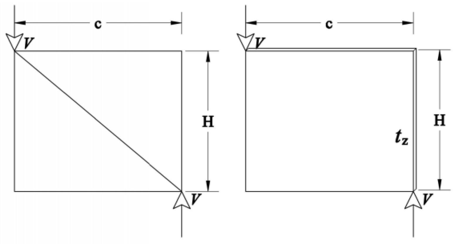
2.2. Equivalent Wall Thickness

The thin-walled beam resists the torque by the shear flow generated on the cross section when it is twisted. The member deformation of the N-shaped main truss and the X-shaped bottom horizontal frame under the action of shear force V is shown in Figure 5. As shown in Figure 5a,b, when the main truss and the bottom frame truss are sheared, the axial deformation is mainly generated by the inclined web member of the truss structure. As shown in Figure 6, if the thin wall has an equal geometry with the single segment of the main truss producing the same deformation as the truss structure under shear V, the truss can be equivalent to the thin wall in torsion resistance, and the thickness of the equivalent thin wall is just tz.
The equivalent wall thickness tz of the N-shaped main truss [16] can be calculated according to Equation (2):
t z = c H E A x G ( c 2 + H 2 ) 3 / 2
where c is the length of one plate of the truss; H is the bridge height; Ax is the cross-sectional area of the diagonal web member; E is the elastic modulus of the material; and G is the shear modulus of the material.
The equivalent wall thickness tx of the X-shaped bottom frame [16] can be calculated according to Equation (3):
t x = 2 c b E A p G ( c 2 + b 2 ) 3 / 2
where c is the length of one plate of the truss; b is the bridge width; Ap is the cross-sectional area of the diagonal web member of the X-shaped frame; E is the elastic modulus of the material; and G is the shear modulus of the material.

3. Example and Finite Element Analysis
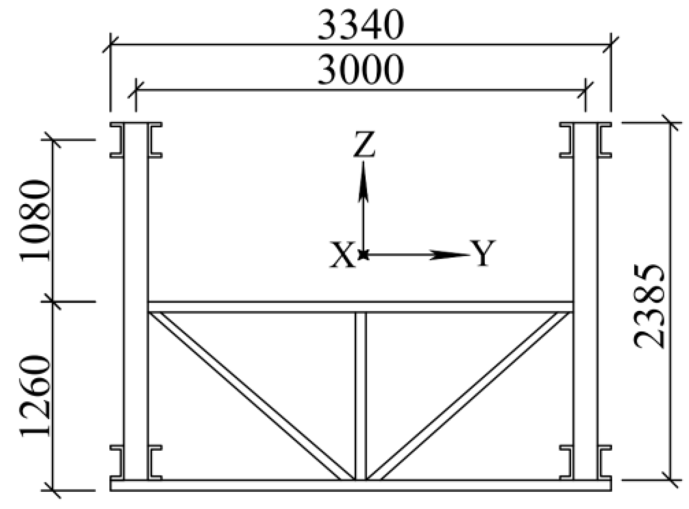
3.1. Example

An aluminum alloy half-through truss footbridge in operation is selected for analysis. Figure 7 and Figure 8 are the elevation and the cross-section of the main girder of the half-through bridge, respectively. The span of the bridge is 30.6 m, and there are 12 equal length plates in total. The plate length, c, is 2.55 m; the distance between the two main trusses (bridge width), b, is 3 m; the calculated height, H, of the main truss is 2.355 m; the height of the vertical web above the top member of the transverse girder is 1.080 m; and the length, h, of the vertical web below the top surface of the upper beam is 1.260 m. The main truss is an n-shaped truss, and the horizontal connection at the bottom is X-shaped. The bridge material is 6082 T6 aluminum alloy, the elastic modulus E is 71 Gpa, the shear modulus G is 26 Gpa, and the Poisson ratio is 0.33. Table 1 shows the section parameters of each component.

3.2. Finite Element Analysis

To verify the correctness of the equivalent section theory, the cantilever beam model is used for calculation and analysis. The finite element model is established by the beam element and calculated by the mature and reliable commercial software MIDAS-Civil. Apply restraint at one end of the cantilever beam, and this end is noted as the restraint end. Apply torque T at the other end, and this end is noted as the loading end. The torsion angle θ, which is measured at the loading end, can be put into Equation (4) to calculate J′, which is the torsional moment of inertia of the half-through truss bridge [16]:
J = T x G θ
where T is the torque at the loading end; x is the length of cantilever beam; G is shear modulus; and θ is the torsion angle under T.
Figure 9 is the schematic diagram of the loading model which constrains all points in the constraint end. At the loading end, the torque T is applied at the torsional center, and the rigid arm is connected between the torsional center and the joint in the upper member of the transverse girder, so the torque can be transmitted to the main truss and the bottom frame through the transverse girder. The torsion center position can be calculated according to the literature [21]. e is the distance between the torsion center and the midpoint of the bottom member of the transverse girder. e can be calculated by Equation (5):
e = 3 H 2 6 H + b
where b is the bridge width, and H is the bridge height.

3.3. Analysis of Calculation Results

The finite element calculation model is a cantilever beam, and the torsional moment of inertia calculated by Equation (4) will be greater than the analytical solution obtained by Equation (1). According to the existing research on the torsional moment of inertia of the plate-truss composite girders of cable-stayed bridge and space trusses, when x (the cantilever length) reaches a certain degree, the restraint of the restraint end has little effect on the loading end, and the calculated value by Equation (4) is almost consistent with the free torsional moment of inertia by Equation (1). At the same time, the closed area of plate-truss composite girder and space truss is exceedingly larger than the size of the chord. Thus, compared with the torsion resistance effect from the chord against warping deformation, the torsion resistance effect from the equivalent closed section (the free torsional moment of inertia) is much greater. Therefore, for the closed truss girder, the free torsional moment of inertia can be directly used to represent its torsional stiffness.
There is still no similar study on the half-through truss bridge. We make a preliminary observation with the change of x from 10.2 m (the main truss has 4 plates) to 61.2 m (the main truss has 24 plates). With the change of x, the analytical solution obtained from Equation (1) and the finite element value from Equation (4) are shown in Figure 10.
As shown in Figure 10, the analytical value calculated by the equivalent open thin-walled member is almost zero, and the finite element value is much greater than the analytical value. Even when the cantilever length reaches 60.2 m, the finite element value is higher than the analytical value by several orders of magnitude. Compared with the trusses which can form a closed area, the open trusses have very low torsion resistance to overall torsional deformation. For the half-through truss bridge, the calculation formula of free torsional moment of inertia cannot approximately represent its torsional stiffness.
Obviously, space warping can cause the bending of the chords on the truss. The volume of the half-through truss bridge is small, and the area of the chord occupies a significant part of the cross-sectional area of the whole bridge. Considering the significant size effect, the torsion resistance of the chord cannot be ignored. Therefore, the torsional moment of inertia of the equivalent open section of the main girder of the half-through truss bridge should be corrected.

4. Calculation Correction Considering Restraint Torsional Effect

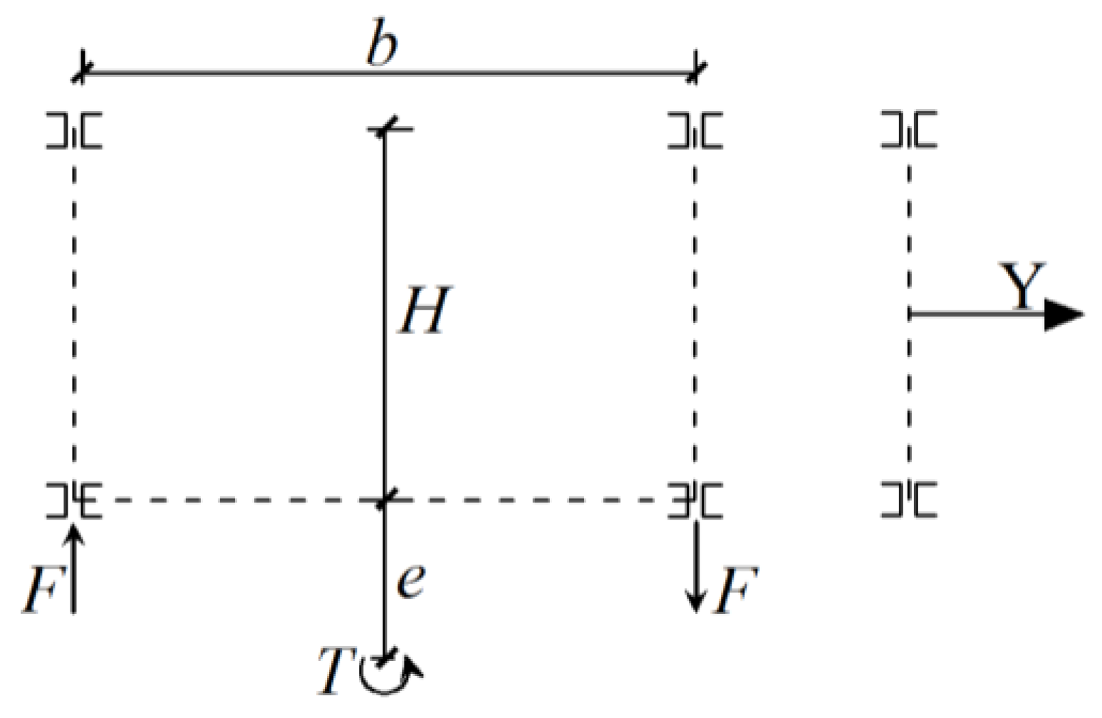
4.1. Torsional Characteristics of Half-Through Truss Girder

For the open thin-walled member, the warping normal stress, which distributes on the section under restrained torsion, is shown in Figure 11. The warping normal stress distributed on the section will form three equivalent bending moments. The bending moment acting on the bottom wall is much smaller than the double moment acting on the side wall. As shown in Figure 11, under the equivalent bending moment, the thin-walled member will produce spatial warpage. In theory, the deformation of the half-through truss bridge should be consistent with the deformation of the open thin-walled member.
Firstly, the torsional characteristics of the half-through truss bridge are analyzed. The deformation of the truss bridge during torsion is shown in Figure 12a, which can be decomposed into transverse deformation and vertical deformation as shown in Figure 12b,c. It can be seen from Figure 12a that the torsion of the whole bridge will certainly cause the spatial warpage of the truss structure, and the warping deformation will inevitably drive the chord to produce transverse bending and vertical bending. Figure 12a fits with Figure 11, demonstrating that the finite element analysis and the mechanistic model can be validated and interpreted by each other.
Because the spatial volume and span of the half-through truss bridge are relatively small, at this time, the chord has a large torsional restraint effect on the main beam. The above truss-wall equivalent theory, which does not consider the torsional resistance of the chords, will inevitably lead to the theoretical value being much smaller than the finite element calculation result. Considering the effect of the chords, the torsional characteristics of the half-through truss bridge should be further analyzed.
According to Figure 11, the truss structure will be subjected to a transverse bending moment. As shown in Figure 12b, this is different from the lower chords, and the two upper chords cannot form a stable system, so the transverse bending stiffness of one upper chord is very low. Driven by torque, although the upper chord will produce significant transverse bending deformation, the torsional resistance is actually not strong due to the low stiffness of the single upper chord, so the torsional resistance from the transverse bending resistance of the upper chords can be ignored.
According to the warping normal stress and equivalent moment of the thin-walled member shown in Figure 11, it can be seen that the bending moment acting on the bottom wall is much less than the bending moment acting on the walls on both sides. It can be seen from Figure 12b,c that the transverse bending deformation of the bottom structure is actually much less than the vertical deformation of the main truss. Combined with the mechanism analysis, we can determine that the vertical bending of the two main trusses has a much higher effect on resisting torsion than the transverse bending of the bottom structure.
The torsional resistance from the transverse bending of the bottom structure is small, and the purpose of this paper is to reveal the torsional mechanism of the half-through truss bridge, rather than to obtain a very accurate analytical solution to torsional stiffness. Therefore, the transverse bending effect of the bottom chords is also ignored, as to facilitate the subsequent work on theoretical correction.
As shown in Figure 12c, the torsional deformation causes the vertical bending of the left and right main trusses with obvious up and down staggered movement. The double moments acting on both sides are significant. At the same time, the upper and lower chords of the main truss form a stable system by the connection of web members. Therefore, the torsion resistance from the vertical bending stiffness of the main truss should be considered. The half-through truss pedestrian bridge has several transverse girders of significant height, and these transverse girders are equivalent to some firm and reliable stiffeners, so the section distortion is ignored.
As shown in Figure 13, e is the distance from the torsion center to the midpoint of the bottom wall, which can be calculated according to Equation (5). To counteract the torque T acting on the member, it is necessary to generate a torque with the same value opposite of the direction of T. We have set the vertical bending resistance of the main truss to assist in the torsional resistance. Thus, the left and right main trusses can respectively generate the force of F inverting up and down to form a torque in the opposite direction of T.
Then, F forming a torque in the opposite direction of T can be calculated by Equation (6):
F = T b
where T is the torque acting on the bridge, and b is the width of the bridge.

4.2. Correction of Theoretical Value of Torsional Stiffness

Set the correction value of the torsional moment of inertia as Jx, and take the cantilever beam as the boundary condition. Calculate the torsional angle under the action of torque T, and then bring the torsional angle into Equation (4) to calculate Jx.
According to the deformation calculation method of the cantilever beam [22], the vertical deflection w of the single-sided truss under the action of force F is:
w = F x 3 3 E I s = T x 3 3 b E I s
where Is the vertical bending moment of the inertia of the single-sided main truss; x is the length of the cantilever beam; E is the elastic modulus of the aluminum alloy; b is the width of the bridge; T is the torque acting on the bridge; and the relation between T and F is shown in Equation (6).
Since the upper and lower chords of the main truss are connected into a stable system by web members, and Is can be composed of the sum of the vertical bending moment of the inertia of the upper and lower chords and the parallel displacement axis value of the Y axis (horizontal center line of vertical web member) in Figure 13, Is can be calculated as shown in Equation (8):
I s = 2 I + 0.5 H 2 A
where I is the vertical bending moment of the inertia of the single chord; H is the height of the bridge; and A is the cross-sectional area of the chord. I and A can be calculated by the section parameters given in Table 1, which will not be repeated.
As shown in Figure 14, the vertical deflection of the main truss on one side is w. Due to ignoring the section distortion, the peripheral dimension after the equivalent model remains unchanged.
In theoretical deduction, the structural deformation under the action of torque is regarded as small deformation. The torsional angle is θ, and therefore θ can be expressed as the sine value of θ, i.e., w/0.5b. Thus, the torsional angle, θ, can be calculated by Equation (9) as follows:
θ = T x 3 1.5 b 2 E I s
where T is the torque acting on the bridge; x is the length of the cantilever beam; E is the elastic modulus of the aluminum alloy; b is the width of the bridge; and Is the vertical bending moment of the inertia of the single-sided main truss.
The corrected value of the torsional moment of inertia can be obtained by taking θ into Equation (4). Because G of the aluminum alloy is about one third of E, the corrected value of the torsional moment of inertia Jx is
J x = 4.5 b 2 I s x 2
where b is the width of the bridge; Is the vertical bending moment of the inertia of the single-sided main truss; and x is the length of the cantilever beam.
By superposition of Equations (1) and (10), the corrected torsional moment of inertia Jxz of the main beam can be obtained as follows:
J xz = 1.12 ( 2 H t z 3 + b t x 3 ) 3 + 4.5 b 2 I s x 2
where tz is the thickness of the equivalent side wall; tx is the thickness of the equivalent bottom wall; H is the height of the bridge; b is the width of the bridge; Is the vertical bending moment of inertia of the single-sided main truss; and x is the length of the cantilever beam.
According to Equation (11), in addition to the section characteristics of the chords, the correction value is also related to the bridge width b and the cantilever beam length x. It can be seen that the torsional performance of the half-through truss bridge should be related to the width-span ratio. This is consistent with the results obtained from the existing research through case analysis [23], which confirms the validity of the correction method. Through cases with a different cantilever beam length x and different width b, the corrected torsional moment of inertia of the main beam was calculated, respectively. When changing the cantilever beam length x for analysis, the bridge width is the original width of the calculation example, i.e., 3 m. The calculation results under the changing lengths of cantilever beam are shown in Figure 15.
As shown in Figure 15, the theoretical solutions before correction and after correction are greatly different. Compared with the corrected results, the results before correction are almost negligible, and the correction value accounts for most of the torsional moment of inertia. It is obvious that the torsional performance of the half-through truss bridge almost comes from the function of the main truss resisting spatial warpage by bending. When only the length of the cantilever beam is changed for analysis, the cross section does not change, and the initial moment of inertia does not change. At this time, the change of the torsional moment of inertia after correction only comes from the change of the correction value under the varied length of the cantilever beam. That is, there is no influence of the change of the bending performance on the bottom member. With the change in cantilever length, the modified results agree with the finite element results. The calculated results under different lengths are close to the finite element results, which shows that the modified calculation theory can accurately characterize the torsion of the half-through truss bridge.
When the cantilever length is small, changing the length has a great impact on the correction result. When the length is only increased from 10.2 m to 15.3 m, the span is only increased by 5 m, and the correction result is reduced by 55%. This effect decreases with the increase in the cantilever length. When the length increases from 30.6 m to 45.9 m, the span increases by more than 15 m, and the corrected result also decreases by 55%. When the cantilever beam is longer than 30 m, the strengthening effect from chord bending is no longer obvious, and the line shape of the corrected result tends to be flat. When the cantilever beam is 61.2 m, the results before and after correction are close to the finite element result. It can be seen that for a half-through truss bridge, changing the span length has a great impact on its torsional performance when its span is small. When the fixed length of the cantilever beam is 30.6 m, the calculation results of changing the width of the cantilever beam are shown in Figure 16.
As shown in Figure 16, both the theoretical solution and finite element solution increase rapidly with the increase in width-span ratio. When the bridge width is less than 4 m, the corrected results are still in good agreement with the finite element results. When the width span ratio is greater than 0.1, the theoretical value of the corrected torsional moment of inertia not only is less than the finite element result, but it also has a large error. When the width is 4.5 m, the error can reach 30% of the finite element result. When the width is 9 m, the error can reach 40% of the finite element result. The main reason for the deviation is that this paper only considers the contribution of the vertical bending of the main truss and ignores the effect of the bottom transverse frame. With the increase of bridge width, the bending moment of inertia of the composite section formed by the bottom chords of the two main trusses is also larger, so this deviation appears rapidly with the increase in width. However, when the width is 9 m, the width-span ratio reaches 0.3, which is almost impossible to meet in the half-through truss pedestrian bridge. Therefore, even though the auxiliary torsion resistance of the bottom chord is not considered in the theoretical calculation, the theoretical calculation can still satisfy the bridge with a general width-span ratio. Thus, the theory can be used to explain the torsional characteristics of the half-through truss bridge.
It can be seen from Figure 15 and Figure 16 that when the width-span ratio is changed by changing the width and length, respectively, the torsional moment of inertia increases rapidly with the increase in the width-span ratio. It can be seen that the most important factor affecting the torsional stiffness of the half-through truss bridge is the width-span ratio.

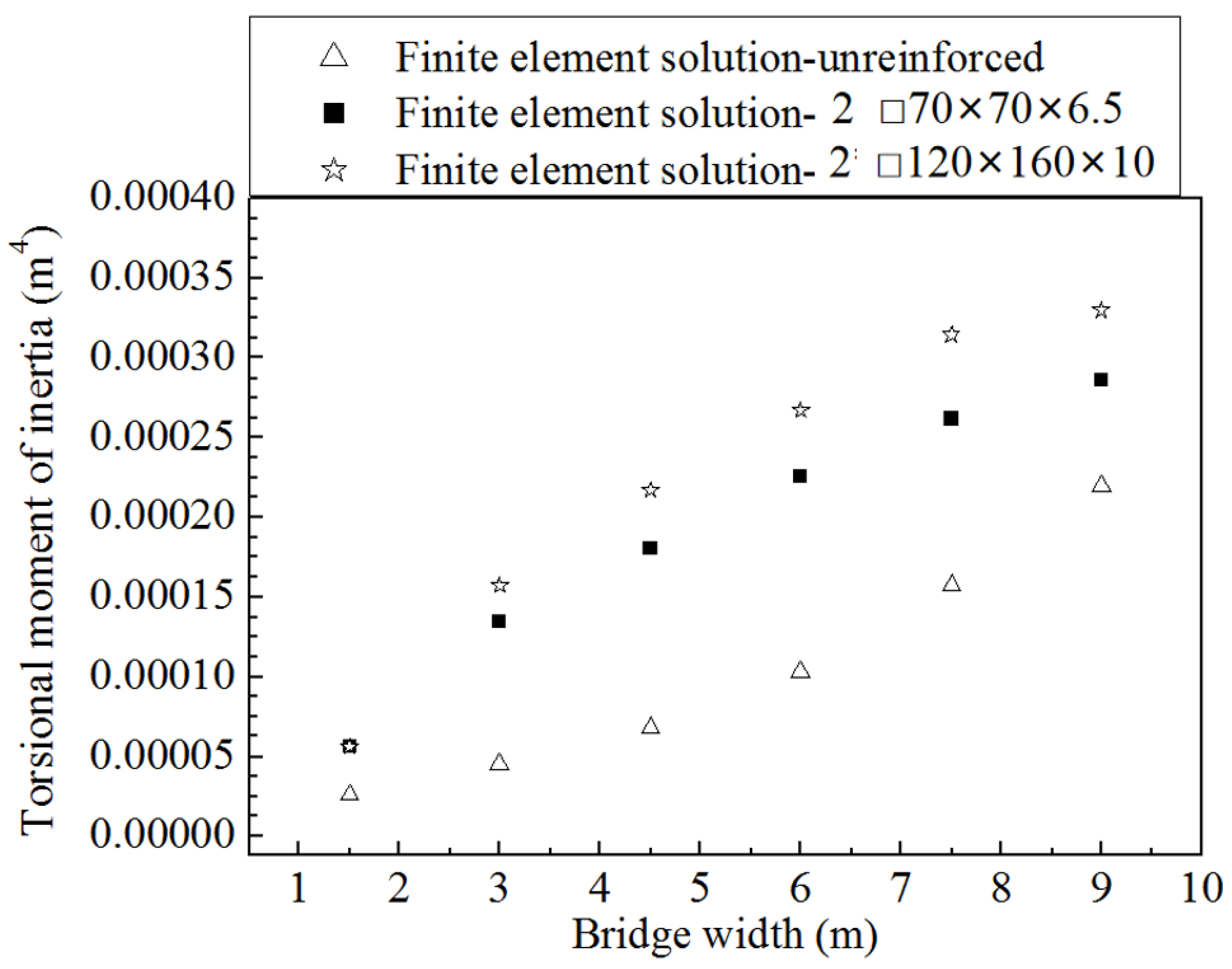
5. Reinforcement Method of Torsional Stiffness and Effect Assessment

5.1. Discussion of Reinforcement Method of Torsional Stiffness

According to the above analysis results, two methods to improve the torsional stiffness are proposed: changing the dimension parameters of structure and adding reinforcing members.
(1)
Change the dimension parameters of bridge structure
The feasibility of changing the dimension parameters is demonstrated first. Apparently, there are two clear methods to improve the torsional stiffness of the main girder of the half-through truss bridge by changing the structural size parameters.
One is to increase the width or increase the height of the main beam to increase the distance between the chord and the torsion center, so the role of the chord in assisting in torsional resistance can be improved.
The other is to reduce the bridge span, that is, to change one span into multiple spans.
However, neither of these two methods is feasible. For the half-through truss bridge, its most important advantages are the open, low height of the main truss and a small, occupied space. Only by substantially raising the height of the main truss can we obtain a considerable increase in torsional stiffness. However, this contradicts the original intention of using this bridge type, i.e., less space occupation. When the height of the main truss is quite high, the through truss bridge with a closed section should be used.
To improve the torsional stiffness of the bridge by changing the width-span ratio, it is necessary to increase the bridge width or change one span to multiple spans to reduce the length of one bridge span. However, the bridge width depends on the traffic capacity required by the traffic flow and determines the material consumption and volume, as well as the bridge structure. It is obviously unreasonable to enhance the bridge width only for improving the torsional stiffness. The magnitude of the span of one bridge also depends on the requirements of the natural environment and traffic and thus cannot be changed at will.
To summarize, strengthening the torsional stiffness of the half-through truss bridge by changing the size parameters of the bridge is not suitable, so strengthening the torsional stiffness requires the other method.
(2)
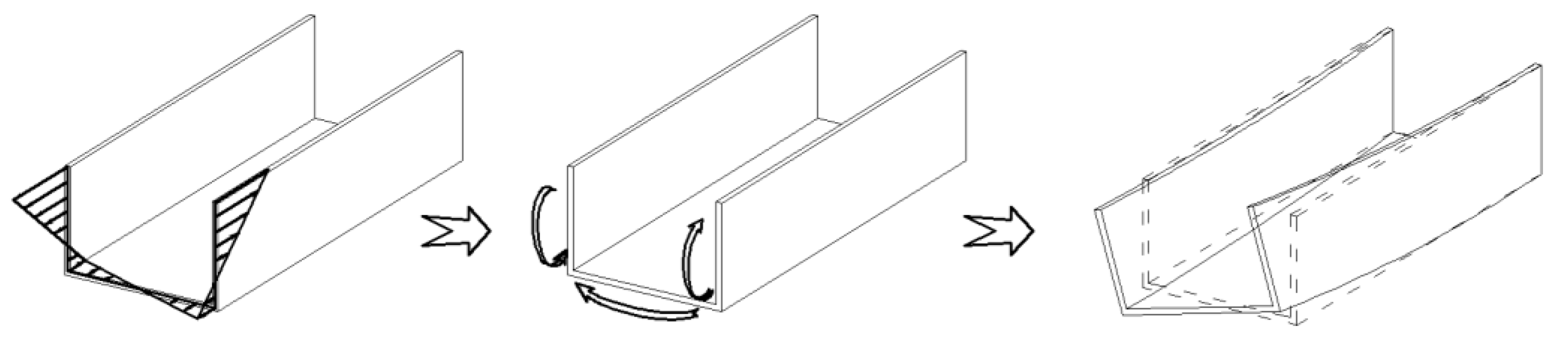
Installation of reinforcing members
Through the literature survey, as shown in Figure 17, it is found that installing the X-shaped battens parallel to the bottom wall between the two sides of the open groove member can play an effective role in strengthening the torsional stiffness [24]. For the half-through truss bridge, its characteristics are similar to those of open thin-walled members, and the vertical web members and transverse girders of each plate can be used as the fulcrums for installing reinforcing members. Its function is equivalent to adding X-shaped battens on the open thin-walled members. As shown in Figure 17, if an X-shaped diagonal brace is installed, the whole bridge will not change too much, and this method can easily be realized from a technical viewpoint. Since this improving method has been well used in open thin-walled members, it is a feasible choice to strengthen the torsional stiffness of the half-through truss bridge by this method.

5.2. Test of the Reinforcement Method

In Section 5.1, strengthening the torsional stiffness by installing X-shaped battens between the upper members of the transverse girders is determined. The effect will be analyzed here. Two sizes are selected for the installed X-shaped battens. They are the double □ 70 × 70 × 6.5 (unit: mm) X-shaped battens and the double □ 120 × 160 × 10 (unit: mm) X-shaped battens. The change of torsional stiffness before and after installing the X-shaped battens is analyzed by using the analysis process of changing the width in Section 4.2. The analysis results are shown in Figure 18.
As shown in Figure 18, the torsional stiffness of the half-through truss bridge increases significantly after installing the diagonal braces between the transverse girders. When the double □ 70 × 70 × 6.5 battens are installed, the torsional moment of inertia after correction is increased by more than 2 times and is even increased by more than 3 times during the width interval of 3~8 m. The improving effect of continuing to increase the size of diagonal braces is not obvious. The significance of strengthening torsional stiffness is not only to improve the deformation performance of the long-span aluminum alloy truss bridge, but also to improve the structural stability of the long-span aluminum alloy truss bridge.
It can be seen that this technique has quite a positive significance for the reinforcement of existing aluminum alloy pedestrian bridges, which can greatly improve the reliability and stiffness of existing bridges without changing the appearance and material of the structure and large-scale disassembly. Furthermore, we perform an assessment of the beneficial effect of the reinforced bridge in resisting erosion, earthquakes, and shock.

5.3. Effect Assessment

Take the existing bridge in Section 3.1 as an example. If the double □ 70 × 70 × 6.5 battens were installed between the upper transverse girders of this bridge with a width of 3 m, its torsional stiffness may increase nearly three times, as in Figure 18. Using the finite element method to do the buckling analysis, we calculated the buckling loads of the reinforced bridge and the unreinforced bridge.
The buckling analysis shows that the bearing capacity of the strengthened bridge is 43% higher than that of the unreinforced one. The torsional reinforcement method is effective and therefore has relevant beneficial effects on the following aspects.
(1)
Resisting erosion.
The half-through bridges made from an aluminum alloy congenitally have good performance on anti-erosion. When their stiffness and bearing capacity are enhanced, these bridges can better resist material fatigue under the same load. Fewer fatigue cracks can further make the erosion resistance of the aluminum alloy better.
(2)
Resisting earthquake and shock.
Earthquake and shock are important extreme loads influencing bridge safety. The higher stiffness and bearing capacity can improve the safety and comfort of the bridge under shock. When encountering an earthquake, the higher stiffness and bearing capacity can make the bridge produce less deformation and make it harder to damage, so the safety factor of the bridge is enhanced. The strengthening method in this paper is beneficial to improve the existing bridge to resist extreme loads.
Through the strengthening method of this paper, without large-scale disassembly, existing bridges can be improved in resisting extreme loads, such as earthquakes and shock. Without replacing the bridge material, the strengthened aluminum alloy bridges can maintain the advantage of erosion resistance.

6. Conclusions

(1)
Based on the principle of making truss bridges equivalent to thin-walled members, the calculation formula of the free torsional moment of inertia of the half-through truss bridge is deduced. The correction formula of the torsional moment of inertia of the main truss against warping deformation is deduced, and the analytical results are compared with the finite element results. The results show that the modified formula can accurately characterize the torsional principle of the half-through truss bridge, but because the transverse stiffness of the bottom chords is not considered, the error of the analytical solution is more than 10% when the width-span ratio is large. However, it is still applicable to the half-through truss bridge with a general width-span ratio and does not affect explaining the torsional characteristics of the half-through truss bridge.
(2)
The main truss strengthens the torsional stiffness of the whole bridge by resisting warping, which increases rapidly with the increase of the width-span ratio. The corrected value of the torsional moment of inertia is far higher than the uncorrected result, which is the dominant factor of the torque resistance of the half-through truss bridge. The most important parameter affecting the torsional stiffness of the half-through truss bridge is the width-span ratio. The torsional stiffness of the bridge will increase with an increase in bridge width and decrease rapidly with a decrease in bridge span.
(3)
Strengthening the torsional stiffness of the half-through truss pedestrian bridge by blindly strengthening the size of bridge components or increasing the volume of the bridge is not suitable for existing bridges. By analogy with the open thin-walled member, it is found that the torsional stiffness of the whole bridge can be improved by adding X-shaped frames between the transverse girders of the half-through truss pedestrian bridge. The effect of adding X-shaped reinforcing frames is remarkable, which can greatly improve the torsional stiffness. The strengthened torsional stiffness not only can improve the deformation performance of the bridge, but it can also improve the stability of the bridge. This method does not change the appearance and material of the structure and does not require large-scale disassembly. The strengthened aluminum alloy bridges not only can maintain the advantage of corrosion resistance, but can also be improved in resisting extreme loads, such as earthquakes and shock.

Author Contributions

Conceptualization, Z.Y. and Y.D.; funding acquisition, Y.D.; investigation, Q.W.; methodology, Z.Y. and Q.W.; resources, Z.Y. and Q.W.; software, Z.Y., Y.D. and Q.W.; validation, Z.Y.; writing—original draft, Z.Y.; writing—review and editing, Y.D. All authors have read and agreed to the published version of the manuscript.

Funding

The Fund for Distinguished Young Scientists of Jiangsu Province (Grant BK20190013), the National Natural Science Foundation of China (Grants 51978154, 52008099, and 51608258), Natural Science Foundation of Jiangsu Province (Grant. BK20200369), and the Fund for Jiangsu Graduate Research and Practice Innovation Program (Grant KYCX21_0116).

Institutional Review Board Statement

Not applicable.

Informed Consent Statement

Not applicable.

Data Availability Statement

Not applicable.

Acknowledgments

The authors would like to thank the editors and the anonymous reviewers for their valuable comments on the content and the presentation of this article.

Conflicts of Interest

The authors declare no conflict of interest.

References

  1. Wen, Q.J.; Ren, Z.J. Structural analysis of a large aluminum alloy truss double-arch bridge. Structures 2021, 29, 924–936. [Google Scholar] [CrossRef]
  2. Heitel, S.; Koriath, H.; Herzog, C.S.; Specht, G. Comparative life-cycle cost analysis of pedestrian bridges made from different materials. Bautechnik 2008, 85, 687–695. [Google Scholar] [CrossRef]
  3. Das, S.K.; Kaufman, J.G. Aluminum alloys for bridges and bridge decks. Miner. Met. Mater. Soc. 2007, 61–74. [Google Scholar]
  4. Wen, Q.J.; Yue, Z.X. Nonlinear stability of the upper chords in half-through truss bridges. Steel Compos. Struct. 2020, 36, 307–319. [Google Scholar]
  5. Raza, S.; Khan, M.K.I.; Menegon, S.J.; Tsang, H.; Wilson, J.L. Strengthening and Repair of Reinforced Concrete Columns by Jacketing: State-of-the-Art Review. Sustainability 2019, 11, 3208. [Google Scholar] [CrossRef] [Green Version]
  6. Dey, P.; Narasimhan, S.; Walbridge, S. Evaluation of Design Guidelines for the Serviceability Assessment of Aluminum Pedestrian Bridges. J. Bridge Eng. 2017, 22, 4016109. [Google Scholar] [CrossRef]
  7. Yu, J.L.; Luo, Y.Z. Influence of torsion stiffness of spatial truss string system on structural stability. J. Zhejiang Univ. (Eng. Sci.) 2013, 47, 1353–1360. [Google Scholar]
  8. Li, G.H. Study on the Theory of Bridge and Structure; Shanghai Science and Technology Literature Press: Shanghai, China, 1983; pp. 122–123. [Google Scholar]
  9. Adamakos, T.; Vayas, I.; Petridis, S.; Iliopoulos, A. Modeling of curved composite I-girder bridges using spatial systems of beam elements. J. Constr. Steel Res. 2011, 67, 462–470. [Google Scholar] [CrossRef]
  10. Vayas, I.; Adamakos, T.; Iliopoulos, A. Spatial systems for modelling steel-concrete composite bridges-comparison of grillage systems and FE models. Steel Constr. 2010, 3, 100–111. [Google Scholar] [CrossRef]
  11. Smyrnaios, S.; Iliopoulos, A.; Vayas, I. Truss models for inelastic stability analysis and design of steel plate girders. Eng. Struct. 2015, 105, 165–173. [Google Scholar] [CrossRef]
  12. Okumura, T.; Watanabe, H. An Investigation of Truss Bridges Under Torsional Loading. Proc. Inst. Civ. Eng. 1965, 121, 1–9. [Google Scholar] [CrossRef] [Green Version]
  13. Xu, G. Calculation of torsional moment of inertia of Space Truss. J. Taiyuan Univ. Sci. Technol. 1984, 1, 46–57. [Google Scholar]
  14. Giltner, B.; Kassimali, A. Equivalent Beam Method for Trusses. Pract. Period. Struct. Des. Constr. 2000, 5, 70–77. [Google Scholar] [CrossRef]
  15. Zhou, X.H.; Qin, F.J.; Di, J.; Qiao, P. Continuous Analysis Method for Deck-truss Composite Stiffening Girder Based on Energy Principle. China J. Highw. Transp. 2014, 2710, 34–43. [Google Scholar]
  16. Li, Y.L.; Wang, L.; Xiang, H.Y.; Chen, Z.X. A Computational method of torsional moment of inertia of plate truss girders. Eng. Mech. 2018, 35, 125–131. [Google Scholar]
  17. Tamura, S. Composite construction of suspension truss and floor slab (No. 1). Bridge 1974, 10, 38–52. [Google Scholar]
  18. Xu, Y.L.; Ko, J.M.; Yu, Z. Modal analysis of tower-cable system of tsing ma long suspension bridge. Eng. Struct. 1997, 19, 857–867. [Google Scholar] [CrossRef]
  19. Siekierski, W. Equivalent moment of inertia of a truss bridge with steel-concrete composite deck. Struct. Eng. Mech. 2015, 55, 801–813. [Google Scholar] [CrossRef]
  20. Xiong, B.; Luo, X.L.; Tan, H. Analysis of Torsional Stiffness of All-composite Truss. Acat Mater. Compos. Sin. 2015, 32, 501–507. [Google Scholar]
  21. Chen, B.Z. Mechanics of Thin-Walled Structures; Shanghai Jiaotong University Press: Shanghai, China, 1998; pp. 96–97. [Google Scholar]
  22. Yan, S.P. Mechanics of Materials; Science Press: Beijing, China, 2012; pp. 100–101. [Google Scholar]
  23. Yue, Z.X.; Wen, Q.J.; Zhuo, T. Stability Analysis of Half-Through Truss Bridge. Eng. Mech. 2018, 35, 270–277. [Google Scholar]
  24. Murthasmith, S.E. Cross Stiffeners for Beams in Torsion. J. Struct. Eng. 1995, 121, 1119–1124. [Google Scholar] [CrossRef]
Figure 1. Long span pedestrian bridges made from aluminum alloy half-through trusses.
Sustainability 14 06628 g001
Figure 2. Correlation between stability and torsional stiffness of half-through truss bridges.
Sustainability 14 06628 g002
Figure 3. One segment of the half-through truss bridge.
Sustainability 14 06628 g003
Figure 4. The simplified bridge cross section and the equivalent section of the open thin-walled girder: (a) bridge cross section; (b) equivalent open thin-walled beam section.
Sustainability 14 06628 g004
Figure 5. Shear deformation of two types of trusses: (a) N-shaped main truss; (b) X-shaped bottom horizontal frame.
Sustainability 14 06628 g005
Figure 6. Truss structure and its equivalent thin wall.
Sustainability 14 06628 g006
Figure 7. Elevation of main girder (unit: mm).
Sustainability 14 06628 g007
Figure 8. Cross section of main girder (unit: mm).
Sustainability 14 06628 g008
Figure 9. Finite element model of the cantilever beam: (a) model diagram; (b) deformation diagram.
Sustainability 14 06628 g009
Figure 10. Calculation results of torsional moment of inertia with changing x (length of cantilever beam).
Sustainability 14 06628 g010
Figure 11. Warping normal stress and equivalent moment on the section of the open thin-walled member and the spatial warpage deformation.
Sustainability 14 06628 g011
Figure 12. Torsional deformation of the half-through truss bridge: (a) torsional deformation; (b) transverse decomposition; (c) vertical decomposition.
Sustainability 14 06628 g012
Figure 13. Schematic diagram of equivalent torsion of the main girder.
Sustainability 14 06628 g013
Figure 14. Schematic diagram of torsional deformation of equivalent model.
Sustainability 14 06628 g014
Figure 15. Corrected calculation results of torsional moment of inertia with changing x.
Sustainability 14 06628 g015
Figure 16. Corrected calculation results of torsional moment of inertia with changing bridge width.
Sustainability 14 06628 g016
Figure 17. Schematic diagram of the thin-walled member with X-shaped battens and the half-through truss bridge installed with torsion-resistant frame.
Sustainability 14 06628 g017
Figure 18. Modified torsional moment of inertia after installing the X-shaped battens.
Sustainability 14 06628 g018
Table 1. Cross sections of different components.
ComponentCross Section of Component (mm)
Upper and bottom chordDouble Sustainability 14 06628 i001 230 × 90 × 12
Web member of the main girder□ 120 × 160 × 10
Upper member of the transverse girder and Web member of the transverse girder□ 70 × 70 × 5
Bottom member of the transverse girderDouble □ 70 × 70 × 5
The X-shaped bottom horizontal frameDouble □ 120 × 160 × 10
Publisher’s Note: MDPI stays neutral with regard to jurisdictional claims in published maps and institutional affiliations.

