Article

Energy-Based Combined Nonlinear Observer and Voltage Controller for a PMSG Using Fuzzy Supervisor High Order Sliding Mode in a Marine Current Power System

by
Youcef Belkhier
1,
Abdelyazid Achour
1,
Rabindra Nath Shaw
2,
Nasim Ullah
3,
Md. Shahariar Chowdhury
4 and
Kuaanan Techato
4,5,*
1
Laboratoire de Technology Industrielle et de l’Information (LTII), Faculté de Technologie, Université de Bejaia, Bejaia 06000, Algeria
2
Department of Electronics & Communication Engineering, Galgotias University, Greater Noida 201306, India
3
Department of Electrical Engineering, College of Engineering, Taif University, P.O. Box 11099, Taif 21944, Saudi Arabia
4
Faculty of Environmental Management, Prince of Songkla University, Hat Yai 90112, Thailand
5
Environmental Assessment and Technology for Hazardous Waste Management Research Center, Faculty of Environmental Management, Prince of Songkla University, Hat Yai 90112, Thailand
*
Author to whom correspondence should be addressed.
Sustainability 2021, 13(7), 3737; https://doi.org/10.3390/su13073737
Submission received: 9 February 2021 / Revised: 15 March 2021 / Accepted: 22 March 2021 / Published: 27 March 2021

Abstract

:
A permanent magnet synchronous generator (PMSG) in s grid-connected tidal energy conversion system presents numerous advantages such as high-power density and ease of maintenance. However, the nonlinear properties of the generator and parametric uncertainties make the controller design more than a simple challenge. Within this paper we present a new combined passivity-based voltage control (PBVC) with a nonlinear observer. The PBVC is used to design the desired dynamics of the system, while the nonlinear observer serves to reconstruct the measured signals. A high order sliding-mode based fuzzy supervisory approach is selected to design the desired dynamics. This paper addresses the following two main parts: controlling the PMSG to guarantee the maximum tidal power extraction and integrate into to the grid-side converter (GSC), for this the new controller is proposed. The second task is to regulate the generated reactive power and the DC-link voltage to their references under any disturbances related to the machine-side converter (MSC). Furthermore, the robustness of the controller against parameter changes was taken into consideration. The developed controller is tested under parameter variations and compared to benchmark nonlinear control methods. Numerical simulations are performed in MATLAB/Simulink which clearly demonstrates the robustness of the proposed technique over the compared control methods. Moreover, the proposed controller is also validated using a processor in the loop (PIL) experiment using Texas Instruments (TI) Launchpad.

1. Introduction

Tidal energy is an environmentally friendly and fully predictable source of energy. Its inherent advantages make a viable source for grid integration [1,2]. Due to low maintenance costs the permanent magnet sonorous generator (PMSG)-based tidal conversion system is integrated into the grid using back to back converters. Additionally, the use of a direct drive PMSG is very interesting for this type of underwater application, where access to the maintenance operations is often very difficult. Other advantages of the PMSG include self-excitation, higher efficiency, and low maintenance cost. For direct drive systems, the generator is directly connected to the turbine and the assembly rotates at the same speed. Therefore, the generator is driven at low speed and the gearbox is eliminated. Thus, the efficiency of the conversion system is improved, and the maintenance requirements are minimized [1,3]. However, from the control system point of view, this conversion system is associated with several issues such as disturbances and parametric uncertainties. Furthermore, fault ride-through capability, efficiency of the power converters, reactive power support, and DC-link voltage control are some of the vital requirements for the tidal power conversion system in grid integration mode [4,5]. During the last few decades, extensive control theories and techniques have been reported in the literature proposing solutions to the stated PMSG problems. A magnetic equivalent circuit method-based second-order sliding mode is proposed in [6]. However, external disturbances and parameter changes have not been considered. In [7], a fuzzy sliding mode controller that adaptively extracts the maximum tidal power under swell effects is developed. However, the parameter variations and uncertainties have not been considered. In [8], a jaya-based sliding mode approach is proposed to enhance the performance of a tidal conversion system. The authors proposed an association of the tidal system with the superconducting magnetic energy system (SCMES), for which the jaya-based controller is applied; however, this association improves the costs and maintenance time only. A novel active disturbance rejection controller as an alternative to the conventional Proportional Integral (PI) control is proposed in [9]. This strategy treats the parameter uncertainties or changes as an element to be rejected which can be canceled during the control design. Nonlinear observer-based second-order SMC combined with a predictive control was developed in [10] for a new hydrostatic tidal turbine by short-term predictions of the tidal speed. The same system is also investigated in [11] using a nonlinear observer-based extreme machine learning integrated sliding mode control. A linear quadratic controller is proposed in [12] using a real profile of the tidal speed. In [13], a perturb and observe algorithm is proposed to track the maximum tidal power. Tilt-based fuzzy cascade control combined with a new Q-network algorithm has been investigated in [14].
Nevertheless, the PMSG physical properties are ignored in the aforementioned control design techniques [15]. Within this work, a novel control method, based on the passivity concept is proposed for tracking the angular velocity of the turbine for maintaining it at the optimal torque. Passivity-based control (PBC) exhibits several advantages such as the fact that it cancels the nonlinear terms in a damped way, along with its guaranteed robustness properties and ensured stability. The main idea of this approach is to reshape the system’s natural energy and inject the required damping in such a way that the control objective is achieved [16]. The present paper investigates a new passivity-based voltage controller and nonlinear observer via a combined fuzzy gain supervisory-high order sliding mode approach. There are two main objectives to be achieved: controlling the PMSG to guarantee the maximum tidal power extraction and integrate this power into the GSC and, to achieve the above goals, a new controller is proposed. The second objective includes the regulation of reactive power and the DC-link voltage. A special focus is given to the machine side converter, as it is the bridge between the tidal turbine and the grid. Furthermore, the robustness against parameter changes was also taken into consideration. Thus far, several research efforts have been made which explore the application of passivity-based controllers for PMSG driven systems. In [17], a PBC-based fuzzy sliding-mode controller is proposed. However, the controller design of the proposed combined strategy is complex due to the mathematical model. A passivity-based sliding-mode control (SMC) is developed in [18] and, as mentioned by the authors, the presented combined PBC–SMC control uses more than six fixed gains which are very difficult to design. As demonstrated by Zhou et al. in [19], fixed gains are very difficult to calculate if the system exhibits parameter variations or uncertainties. The authors in [20] proposed a linear feedback passivity-based controller. However, extensive investigation on the PMSG nonlinear properties and parameter variations has not been conducted. In [3], a novel passivity-linear feedback control combined with a fuzzy logic controller is investigated. In [21], a PBC control is proposed, with a passivity-based PI control. A passivity-based voltage control is developed in [5]; however, as mentioned by the authors, the new controller shows a small sensitivity to the variation of the mechanical parameters. A standard nonlinear passivity-based control that ensures asymptotic convergence to the maximum power point of wind system adaptively is proposed in [22]. The same system was considered by [23], replacing the battery with the DC-link with grid-connection; this modification has significantly complicated the control problem. Therefore, a PI-PBC is adopted to compensate the coupling term for the PMSG. In [24], a robust adaptive passivity-based control scheme is proposed with actuator saturation.
The presented paper is related to the controller proposed in [3] and it is inspired from the work reported in [25]. Main highlights of this work are presented as follows:
  • A new adaptive fuzzy supervisory-high order sliding mode passivity-based combined voltage control and nonlinear observer for optimal performance of a PMSG is developed.
  • The high order sliding mode controller (HSMC) is adopted to design the desired torque dynamics. The proposed method ensures fast convergence of the closed-loop system.
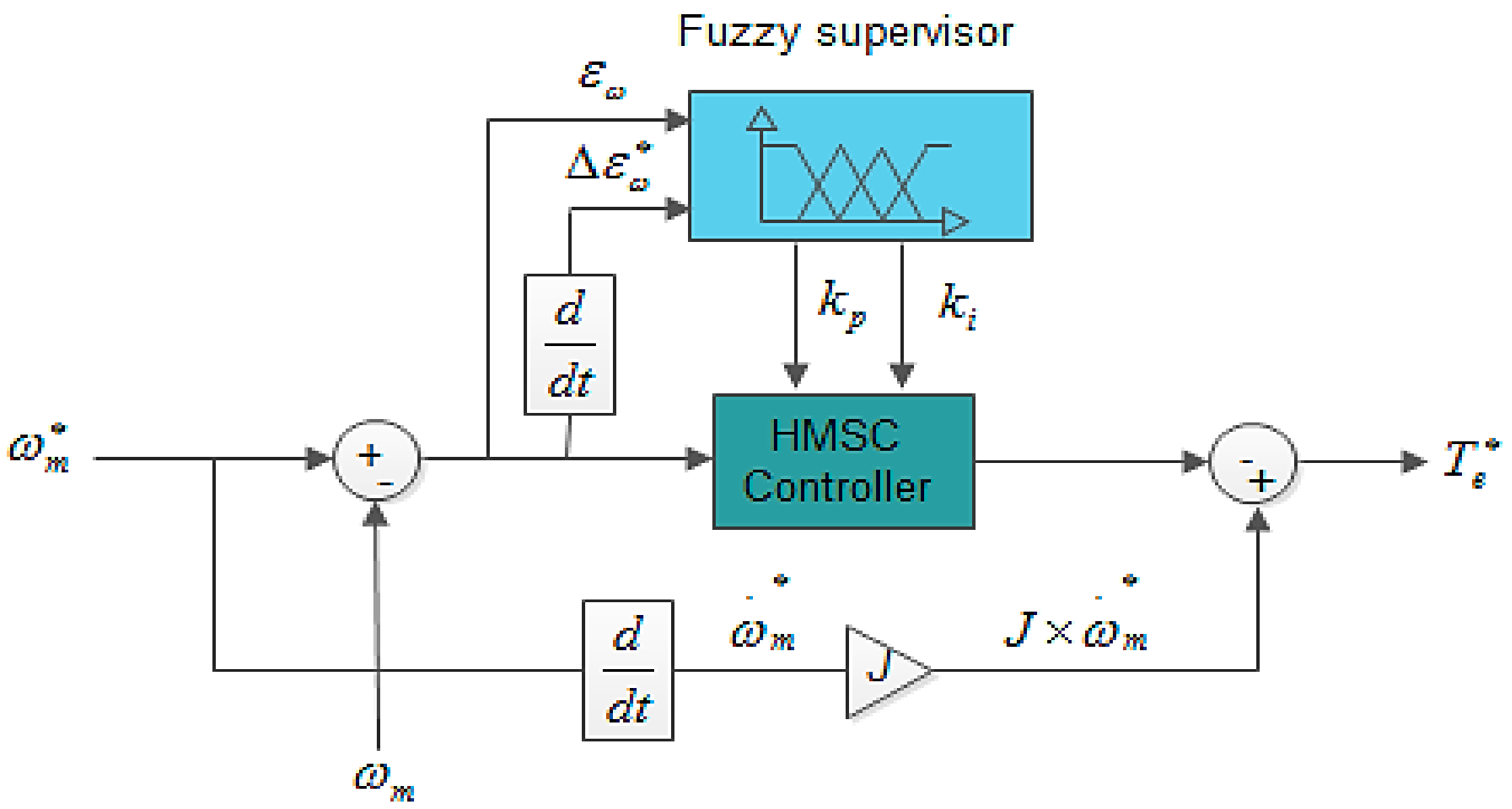
  • The fuzzy gain supervisor is used to adjust gains of the HSMC online. The online gain tuning enhances robustness against various uncertainties.
  • The essential characteristic of this approach is the duality between the controller and observer. Additionally, with the proposed approach, the global stability of the associated observer–controller was analytically proven.
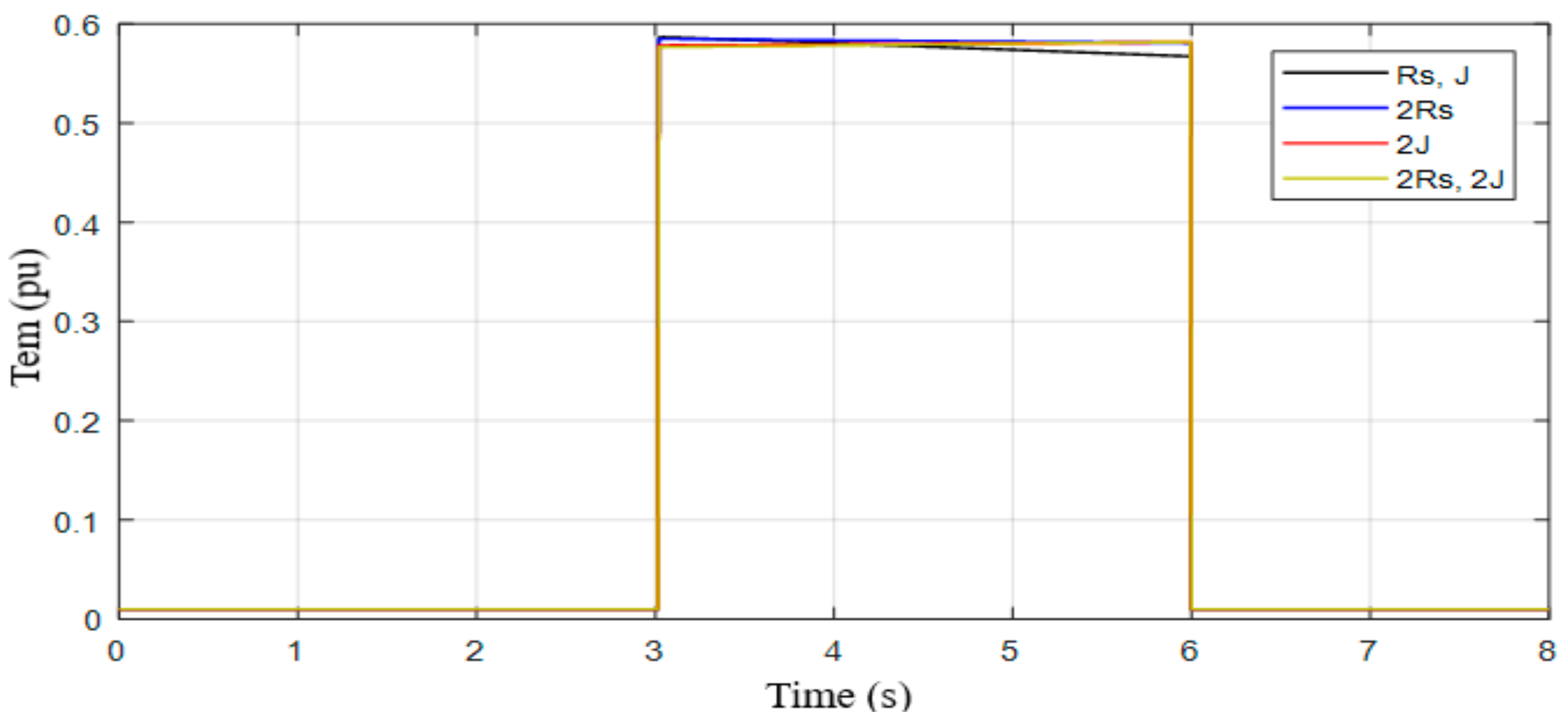
  • The most important contribution of this work includes the compensation of the variation in the moment of inertia J [5].
The rest of this paper is presented as follows: after the introduction section, the mathematical model of the tidal power conversion system is presented in Section 2. The proposed controller is depicted in Section 3. Section 4 deals with the computation of the combined observer–voltage control. Section 5 shows the global stability of the presented strategy. Section 6 illustrates the controller design of the GSC converter. Simulation results are discussed in Section 7. Finally, the conclusion is drawn.

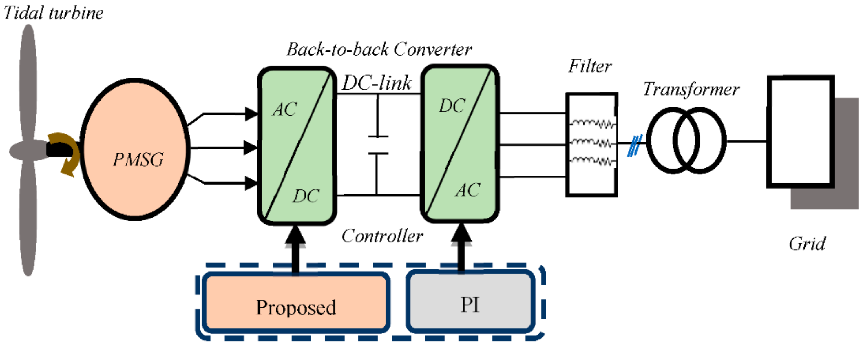
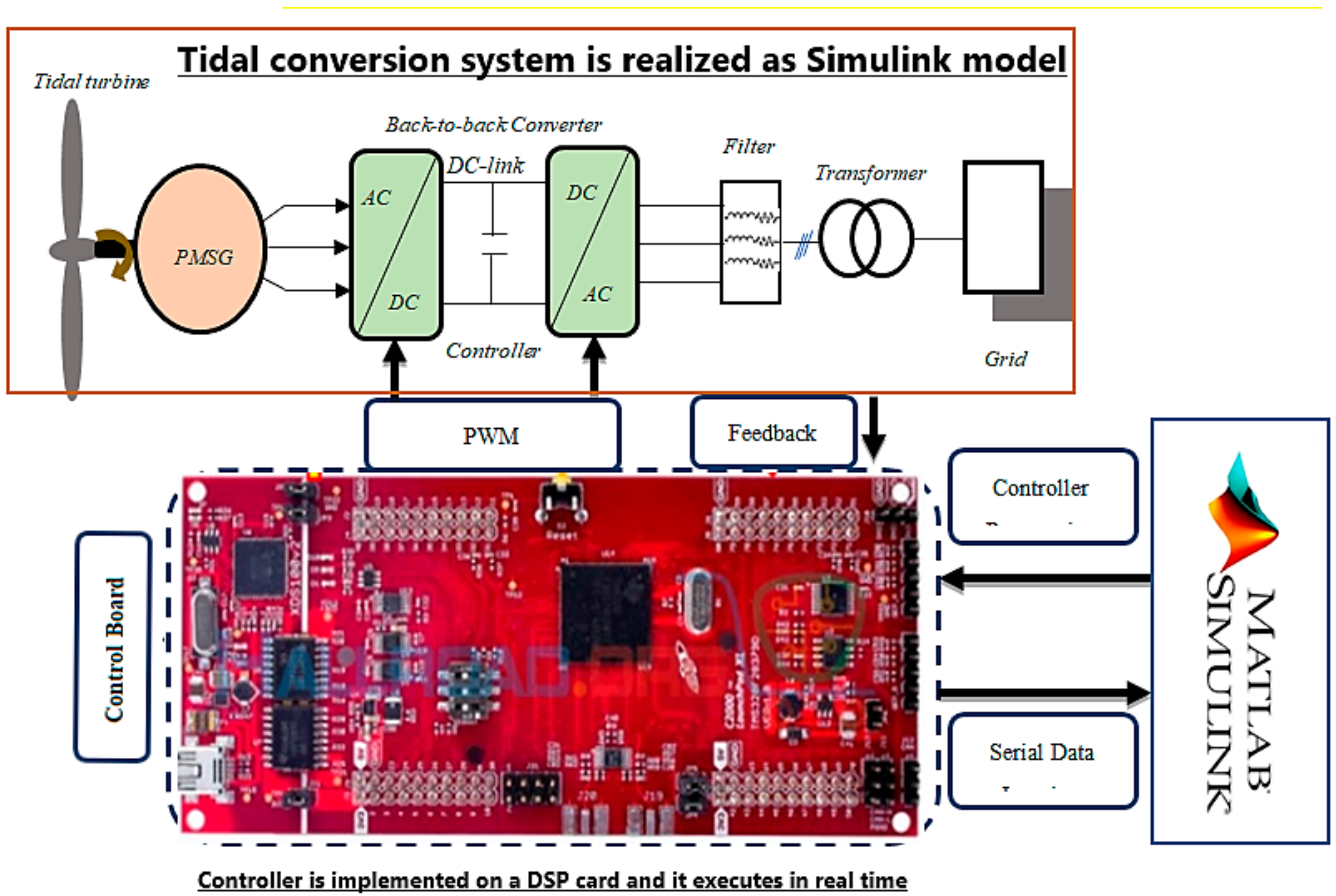
2. Mathematical Model for Tidal Generator System

The investigated power conversion system consists of a tidal turbine, PMSG, AC–DC–AC power converter and the grid. The power produced via the generator is controlled by the proposed nonlinear controller applied to the machine side converter. The GSC converter delivers the active power by using the classical PI technique. The block diagram of the tidal wave conversion system is shown in Figure 1.

2.1. Tidal Power Model

The tidal power captured by the turbine and the corresponding torque is expressed as below [9]:
P m = 1 2 ρ C p β , λ Av t 3
T m = P m ω m
C p β , λ = 0.5 116 λ i 0.4 β 5 e 21 λ i
λ i 1 = λ + 0.08 β 1 0.035 1 + β 3 1
λ = ω m R v t
Where, β denotes the pitch angle, v t is the tidal speed, ρ represents water density, λ denotes the tip-speed ratio, C p represents the power coefficient, A denotes the swept area of the blades, R denotes the radius of the blades, and   ω m represents the speed of the rotor.

2.2. PMSG Model

The PSMG model is expressed as follows [5]:
L α β di α β dt + ψ α β θ e p ω m = v α β R α β i α β
J d ω m dt = T m T e i α β , θ e f fv ω m
T e i α β , θ e = ψ α β T θ e i α β
where T e denotes the electromagnetic torque, ψ α β θ e = ψ f sin θ e cos θ e is the flux linkages vector, ψ f represents the flux linkages due to permanent magnets, i α β = i α i β represents the stator current vector, L α β = L α 0 0 L β denotes the stator induction matrix, f fv is the viscous coefficient, R α β = R S 0 0 R s represents the stator resistance matrix, v α β = v α v β denotes the voltage stator vector, θ e represents the electrical angular, ω m denotes the PMSG speed and p denotes the pole pairs number.

3. Problem Formulation and Proposed Controller Design Procedure

The basic aim of the proposed controller is to make the system passive. This is possible by introducing a damping term and reshaping the system’s energy via the control loop. The application of the adaptive fuzzy supervisory high order passivity-based nonlinear observer and voltage controllers are developed in this paper. Before deriving the controller, several steps are required: first, it is necessary to calculate a Euler–Lagrange model for dividing the system dynamics as input and output vectors such that the relationship between them is passive. Second, the system has to be decomposed into two interconnected subsystems with negative feedback. Finally, the non-dissipative terms in the system model must be identified.
The controller design process is depicted in Figure 2, in which two main parts can be distinguished: The first controller is a fuzzy supervisory-high order sliding mode controller (FS-HSMC). The second one is a passivity-based combined nonlinear observer-based voltage control (PBCOV).

3.1. Problem Formulation

The control problem can be formulated as follows: consider Equations (6)–(8) with the state vector i α β T ,   ω m , θ m T . Where θ m is rotor angular velocity, v α β are control inputs, and T e i α β , θ e ,   ω m T represent the regulated outputs. The problem consists of constructing an observer-based controller such that for a desired output function T e * , global torque tracking with internal stability is achieved.

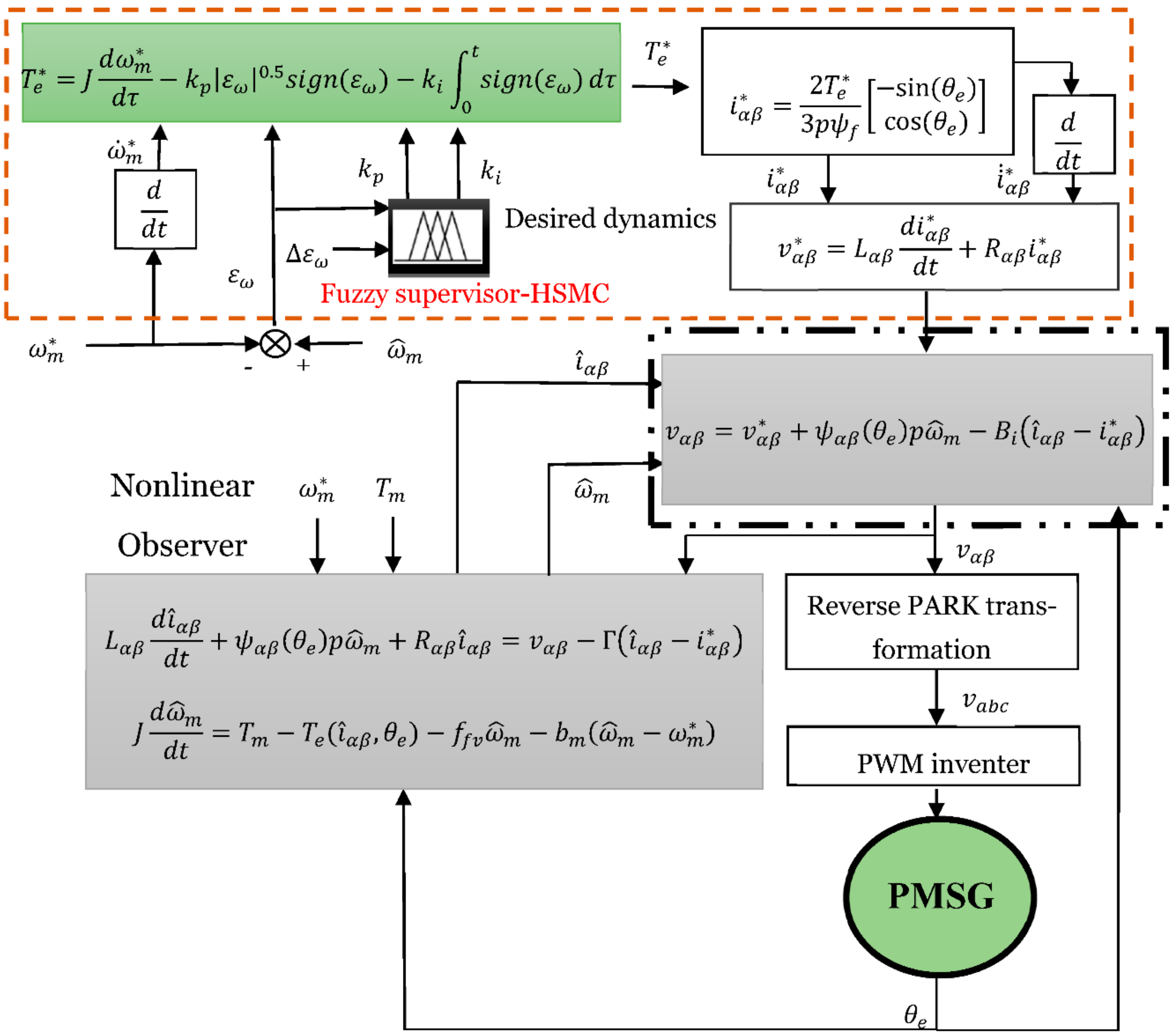
3.2. Passivity-Based Voltage Controller

As mentioned previously, the PBCOV is used to design the control voltage. First, we have to design the passivity-based voltage control (PBVC) [5]. The desired dynamics must be compatible with the bounded constraints of the PMSG. Thus, the following desired dynamics are deduced from the model (6)–(8):
v α β * = L α β di α β * dt + ψ α β θ e p ω m + R α β i α β *
T m = J d ω m * dt T e * i α β * , θ e f fv ω m *
where T e * represents the desired electromagnetic torque, v α β * denotes the desired voltage, i α β * represents the desired current, and ω m * denotes the desired speed. The error dynamics between the PMSG model (6)–(8) and the desired model (9), (10) are described as follows:
v α β v α β * = L α β d ε i dt + R α β i α β * i α β
J d ω m * dt T e * i α β * , θ e f fv ω m * ω m   = 0
The problem is to find control law v α β , which ensures the convergence of the dynamics, i.e., the error between the desired dynamics and the measured, to zero. To this end, we shape the energy of the closed loop to match a desired energy function V f * ε i , as follows:
V f * ε i = 1 2 ε i T L α β ε i
Here, ε i = i α β * i α β represents the current tracking error. The derivative of (13) along the trajectory (11), yields:
V ˙ f * ε i = ε i T R α β ε i + v α β v α β *
Then, the fast convergence of the current tracking error ε i to zero is ensured only if the control law v α β is taken as:
v α β = L α β di α β * dt + ψ α β θ e p ω m + R α β i α β * B i ε i = v α β * B i ε i
Here, B i = b i I 2 is a 2-by-2 matrix of positive gains, and I 2 identity matrix.
Remark 1.
the proof of the passivity property of the PMSG in the αβ-frame is clearly demonstrated by Belkhier et al. in [5]. Thus, it is not considered in the present work. The proof of the exponential convergence of current error is clearly demonstrated in Appendix A.
Remark 2.
In the closed loop system, the positive definite matrix  B i increases the convergence of the tracking error and it overcomes the imprecise knowledge of system parameters.

3.3. Desired Torque Design by Fs-Hsmc

The PMSG operates at an optimal speed if the desired current is designed as follows [16]:
i α β * = 2 T e * 3 p ψ f sin θ e cos θ e
From Equation (12), reference torque is expressed as follows:
T e * = J d ω m * dt f fv ω m * ω m
From Equation (17), the reference torque T e * depends on the PMSG mechanical parameters ( J , f fv ) [5,16]. To solve this issue, in [5], a damping term ( f fv ) was removed and T e * was computed by a PID controller. However, as mentioned by the authors the strategy still has a drawback with the variation of J due to the fixed gains of the PID. Thus, to overcome this shortcoming, a high order sliding-mode controller (HSMC) is introduced to replace the PID loop. It is well known that this control has high robustness and stability compared to PID [6]. Then, Equation (17) is expressed in the following form:
T e * = J d ω m * dt k i ω m * ω m 0.5 sign ω m * ω m k p 0 t sign ω m * ω m d τ
However, as mentioned previously the HSMC shows shortcomings due to the fixed gains k i and k p . To overcome the gain sensitivity to the parameter uncertainties and to tackle an optimal desired torque, a fuzzy logic controller as a fuzzy gain supervisor is adopted as depicted in Figure 3. The fuzzy supervisor is used to adjust gains k i and k p of the HSMC. The inputs of the FS-HSMC are the speed error ε m = ω m * ω m and its derivative ε m .
There are three main steps that are followed in the fuzzy based control design and it includes: fuzzification, rule base and defuzzification. The types of the membership functions used in this paper are triangular and trapezoidal uniformly distributed and symmetrical in the universe of discourse (see Figure 4). The method of partitioning these functions is given according to Lee and Yubazaki [26,27]. Their method is based on the idea of sharing the same parameter among several membership functions. In Table 1, the linguistic variables corresponding to the inputs–outputs of the fuzzy gain scheduling are chosen as: Negative Big (NB), Negative Small (NS), Zero (Z), Positive Big (PB), and Positive Small (PS). The decision-making output is obtained using a Max–Min fuzzy inference where the crisp outputs are calculated by the center of gravity defuzzification method. The overall design of T e by is shown in Figure 3.

4. Passivity-Based Combined Observer and Voltage Control

This section formulates a nonlinear observer to reconstruct the states (currents and rotor speed) from the measurements. To ensure this objective, the passivity approach is adopted to construct the observer. Duality is established between the nonlinear observer and the PBVC control.
Based on the physical structure of the PMSG model (6)–(8) and the controller structure (15), we introduce the current and velocity observer systems as follows:
L α β d i ^ α β dt + ψ α β θ e p ω ^ m = v α β R α β i ^ α β Γ ε ^ i J d ω ^ m dt = T m T e i ^ α β , θ e f fv ω ^ m ρ m ε ^ m T e i ^ α β , θ e = ψ α β T θ e i ^ α β
Here, i ^ α β is the estimated currents, ω ^ m is estimated rotor speed, ε ^ m = ω ^ m ω m represents the estimated speed error, Γ = ρ i I 2 > 0 , ρ m > 0 are the observer gains. Finally, ε ^ i = i ^ α β i α β represents the estimated current error. For computational convenience, the model in (6)–(8) and the estimated model in (19) are rewritten in the compact form as follows:
D X ˙ + A θ e X + W X = N v α β + ζ D X ^ ˙ + A θ e X ^ + W X ^ = N v α β + ζ Κ Ɛ
where W = diag R α β , f fv   , N = diag I 2 , 0 , ζ = 0 0 T m , X ^ = i ^ α β T , ω ^ m T are the observer states, Ɛ = ε ^ i T , ε ^ m T , Κ = diag Γ , ρ m , A θ e = A T θ e = 0 ψ α β θ e p ψ α β T θ e p 0 , and D = diag L α β , J . From (20), the following error dynamics of the nonlinear observer is deduced:
D Ɛ ˙ + A θ e Ɛ + W + Κ Ɛ = 0 3 × 1
The Stability proof of the estimated error Ɛ of the observer is clearly demonstrated in Appendix B.
From the desired error dynamics given by (9), (10) and the nonlinear observer model in (19), the dynamics of the combined observer–voltage controller is deduced as follows:
L α β d i ^ α β d t + ψ α β θ e p ω ^ m + R α β i ^ α β = v α β Γ i ^ α β i α β * J d ω ^ m d t = T m T e i ^ α β , θ e f f v ω ^ m b m ω ^ m ω m *
where b m > 0 . Therefore, the desired torque T e * in Equation (18) becomes.
T e * = J d ω m * d t k i ε ω 0.5 s i g n ε ω k i 0 t s i g n ε ω d τ
where ε ω = ω ^ m ω m * . Then, the voltage controller of the PMSG becomes as follows:
v α β = L α β di α β * dt + R α β i α β * + ψ α β θ e p ω ^ m B i i ^ α β i α β *

5. Global Stability Property of the Proposed Controller
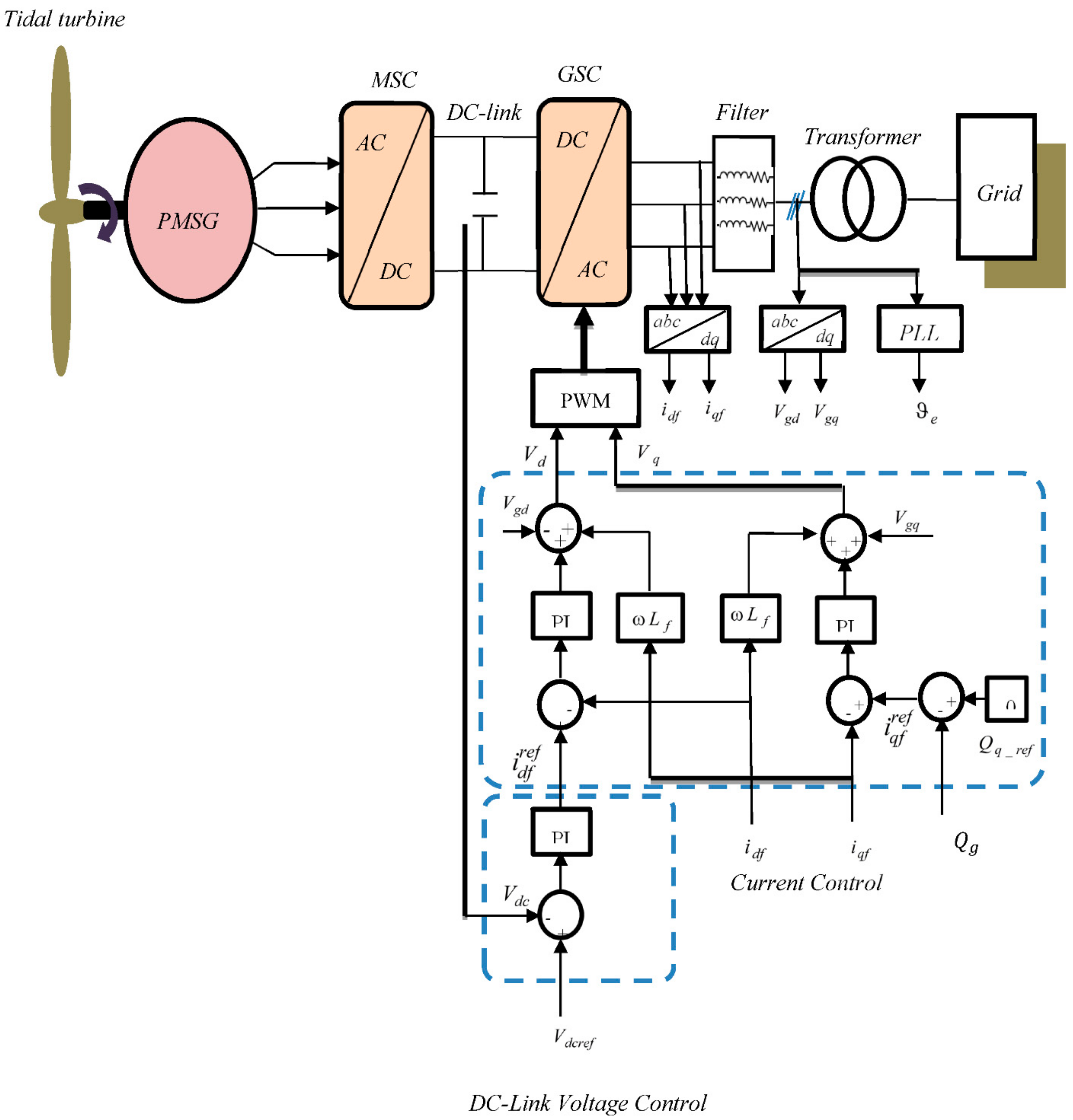
Considering the models (6)–(8), (19) and (22)–(24), the following global dynamics error can be deduced:
D ε ˙ + G θ e ε + F θ e Ɛ = ζ
where, G θ e = R α β + B i 0 2 × 1 ψ α β T θ e f fv + b m , F θ e = Γ ψ α β θ e 0 1 × 2 f fv + ρ m , and ε = ε i T ,   ε m T , Thus, the following proposition is formulated to demonstrate the global stability of the closed-loop observer–PBVC system:
Lemma 1.
The closed-loop system described by Equation (25) is globally stable only if the following conditions are satisfied:
ρ m > ρ e + R s b i > ρ e 4 + R s 2 b m > ρ m 4 + f f v 2
Proof. 
The aim is to prove the convergence of the vector error   e o = ε T ,   Ɛ T T . The energy function is defined as follows:
V o b s ε , Ɛ   = 1 2 ε T D ε + 1 2 Ɛ T D Ɛ
The time derivative of V obs ε , Ɛ along the trajectories (22) and (25) yields:
V obs ε , Ɛ = 1 2 ε T G θ e ε 1 2 ε T F θ e Ɛ 1 2 Ɛ T W + K Ɛ
By re-arranging Equation (28), one obtains the following expression:
V obs ε , Ɛ = e o T Z θ e e o .
where Z θ e = G θ e 1 2 F θ e 1 2 F T θ e W + K . From Equation (29), one can deduce that, if the matrix Z θ e is definitely positive, then the global system is asymptotically stable. This condition is verified only if the following inequality is satisfied:
G θ e W + K 1 4 F θ e F T θ e = Z 11 Z 12 Z 21 Z 22 > 0
where
Z 11 = R α β Γ + B i 1 4 Γ 2 + ψ α β θ e ψ α β T θ e + Γ R α β + Γ 2 1 4 Γ 2 + ψ α β θ e ψ α β T θ e Z 12 = ρ m 4 ψ α β θ e Z 21 = ψ α β T θ e ρ m 4 Γ + R α β Z 22 = f fv b m + ρ m ρ m 2 4
One can see that the inequality (30) is satisfied only if the conditions in (26) are satisfied thus, Z θ e represents positive definite matrix. □

6. GSC Controller

The block diagram of the classical PI strategy is depicted in Figure 5. Its principal aim is to transmit active power to the grid and regulate the DC-bus voltage. The GSC controller is given as below [3,18]:
v d v q = R f i df i qf + L f di df dt ω L f i qf L f di qf dt + ω L f i df + v gd v gq
where v gd and v gq are the grid voltages, i df and i qf are the grid currents, v d and v q denotes the inverter voltages, ω denotes the network angular frequency, R f represents the filter resistance, and L f is the filter inductance. The DC link voltage model is given as below:
C dV dc dt = 3 2 v gd V dc i df + i dc
where C denotes the DC-link capacitance, i dc represents the grid side line current, and V dc denotes the DC-link voltage. The current PI loop is given as:
v gd PI = k gp d i df ref i df k gi d 0 t i df ref i df d τ v gq PI = k gp q i qf ref i qf k gi q 0 t i qf ref i qf d τ
where k gp d > 0 , k gi d > 0 , k gp q > 0 , k gi q > 0 . The q-axis current i qf ref PI is expressed as follows:
i qf ref = k dcp V dc _ ref V dc k dci 0 t V dc _ ref V dc d τ
where k dcp > 0 and k dci > 0 . Finally, the reactive power and active power are given by the following expressions:
P g = 3 2 v gd i df Q g = 3 2 v gd i qf

7. Numerical and Experimental Validation

In this part, numerical simulations are presented to show the feasibility of the proposed strategy. Moreover, the experimental validation of the proposed control schemes is provided using processor in the loop experiment [28,29,30]. The simulated conversion system is based on 1.5 MW rated power. System parameters are listed in Table 2. The reference reactive power is fixed to zero and the DC-link reference is set to 1150 V. By using the imposed pole location method, the damping parameters are chosen as follows: b m = 150 , b i = 250 , ρ m = 60 , ρ e = 700 , and ρ i = 600 . PI gains of the DC-link controller are given as: k dcp = 5 , k dci = 500 . Gains of the current PI loops are chosen as: k gp d = k gp q = 9 and   k gi d = k gi q = 200 . The proposed strategy will be compared to the second-order sliding mode control (SMC) [9], and the conventional (PI) controller methods [19]. Two scenarios are considered. First, the proposed controller is tested with fixed parameter values of the PMSG. The second test is performed with parameter variations and to verify the robustness.

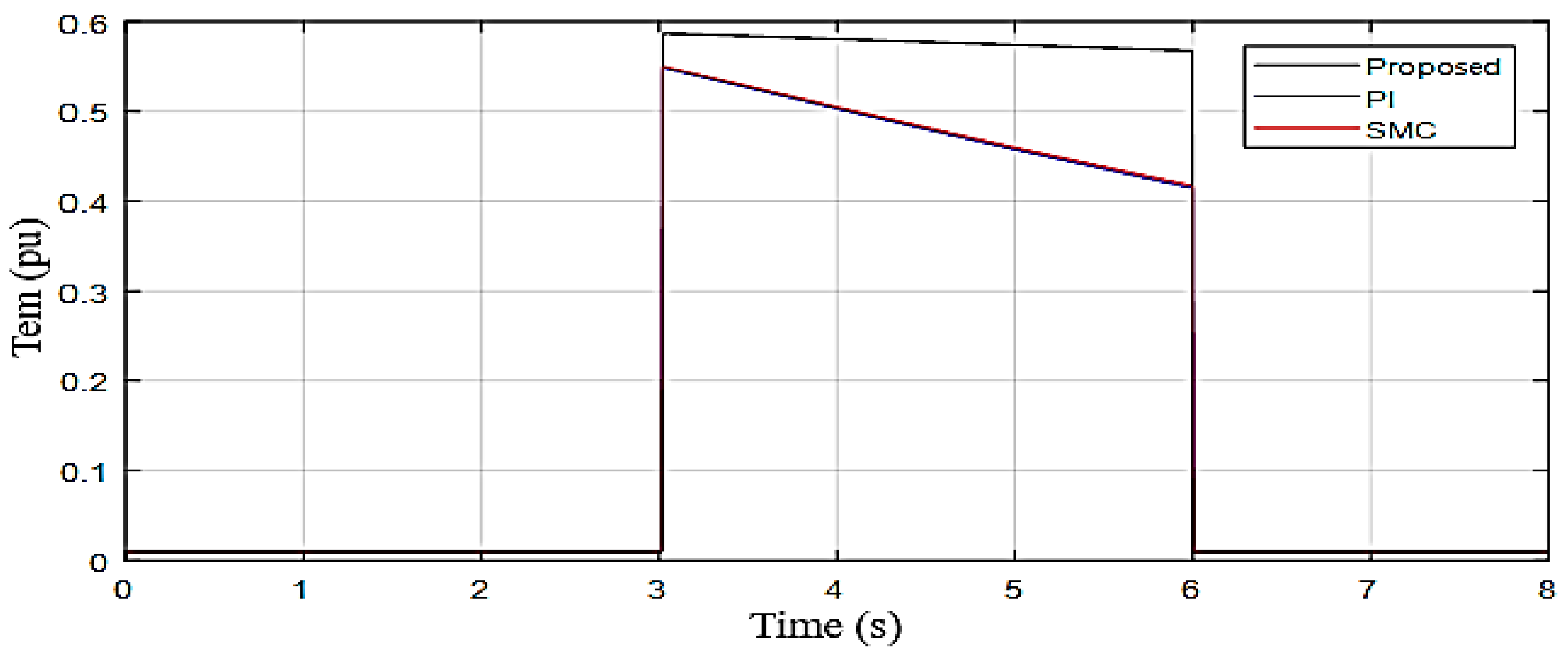
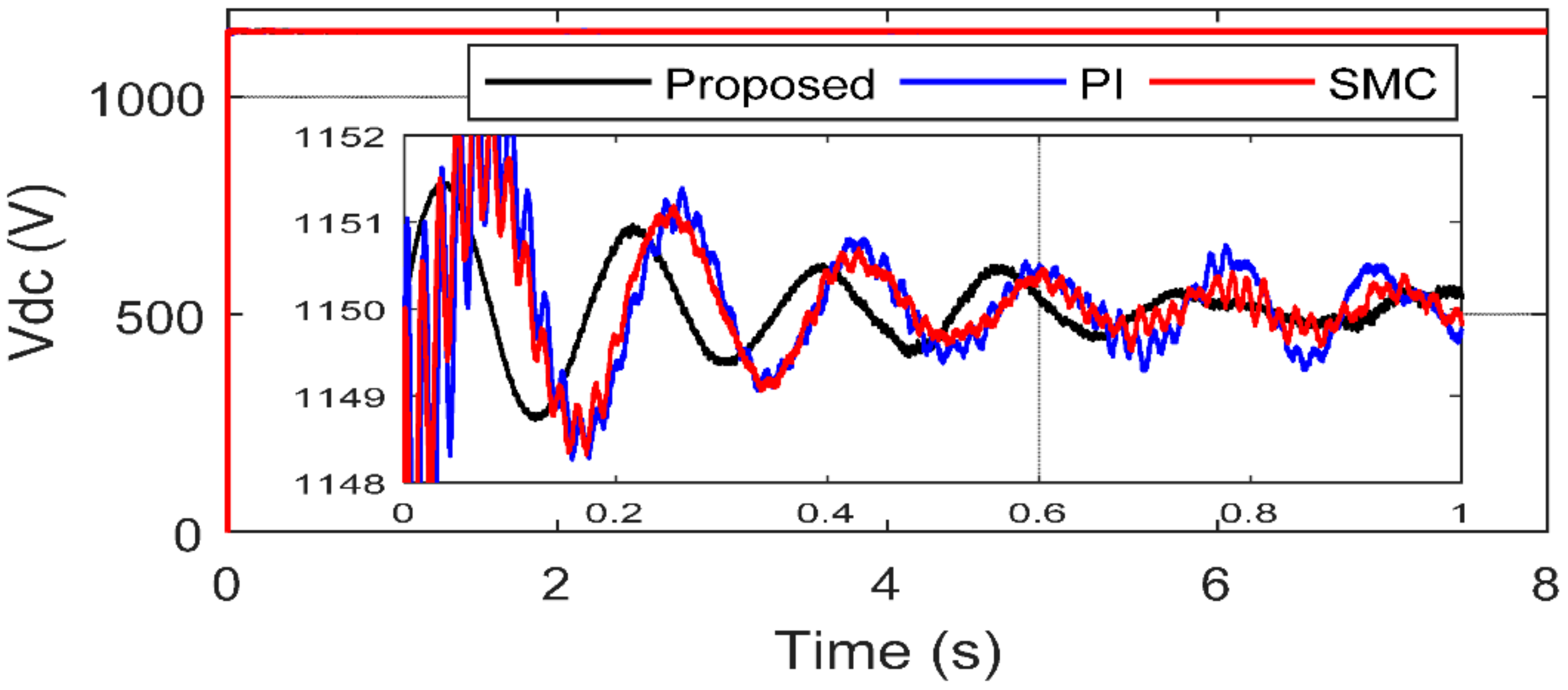
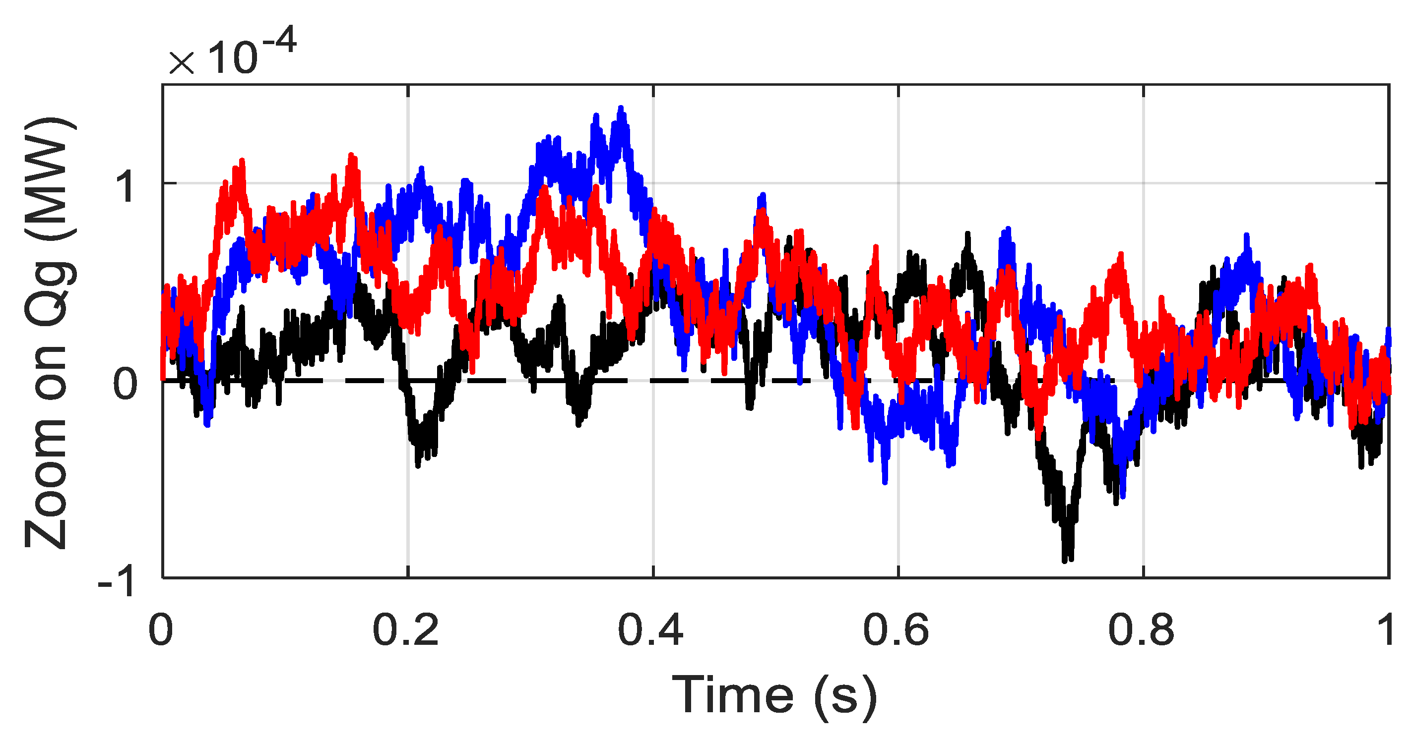
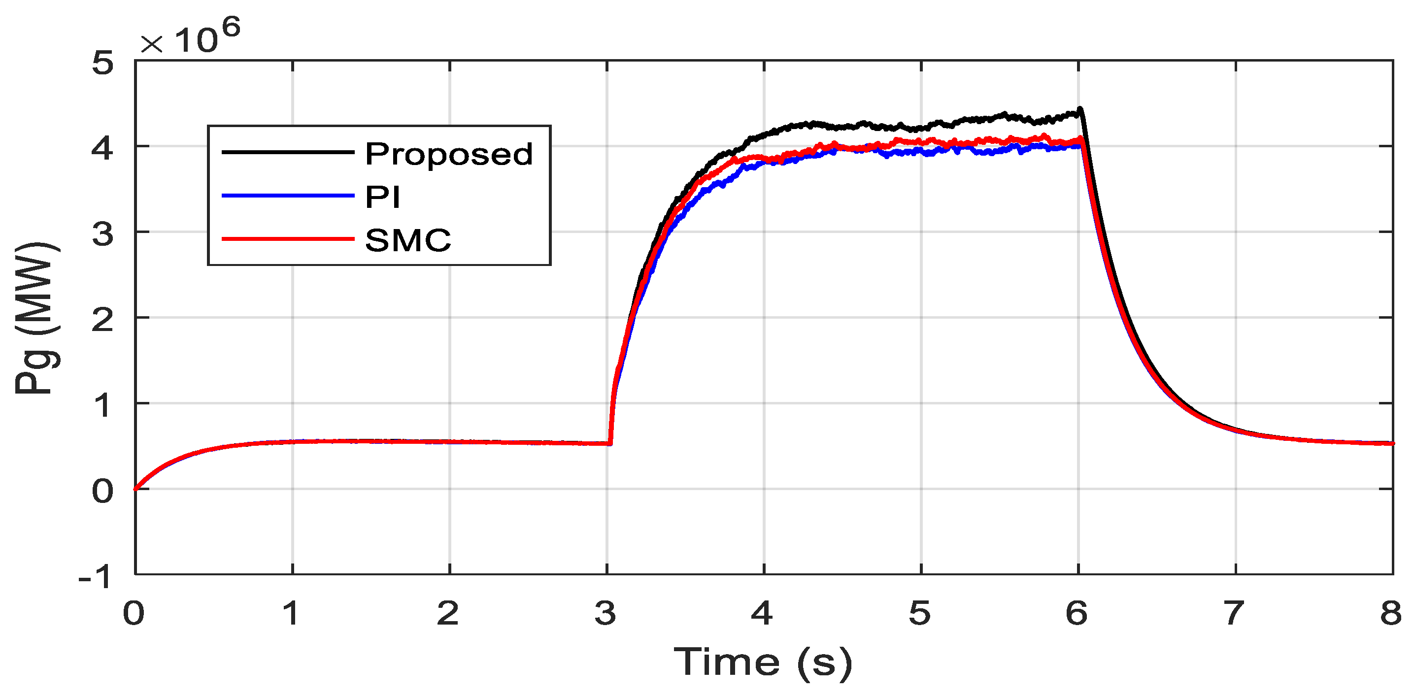
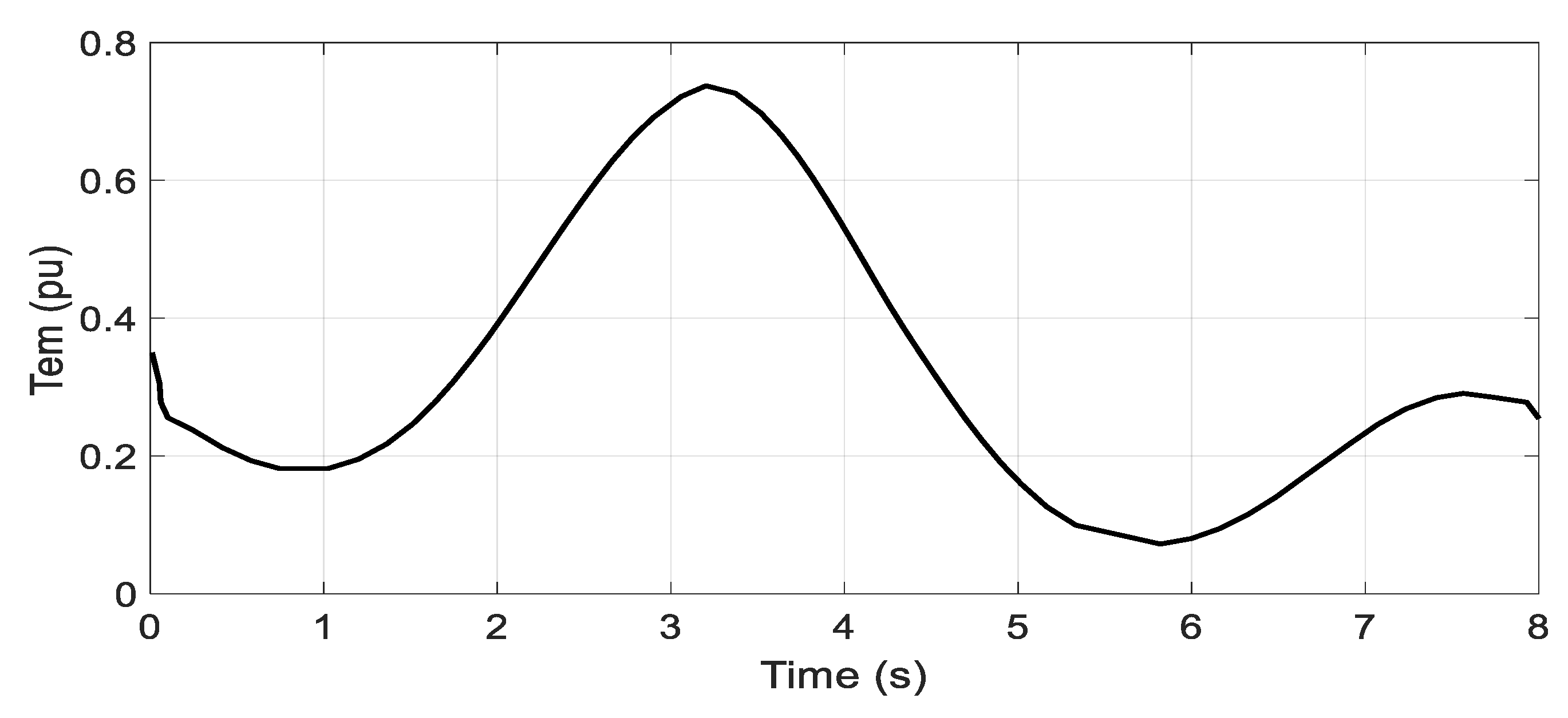
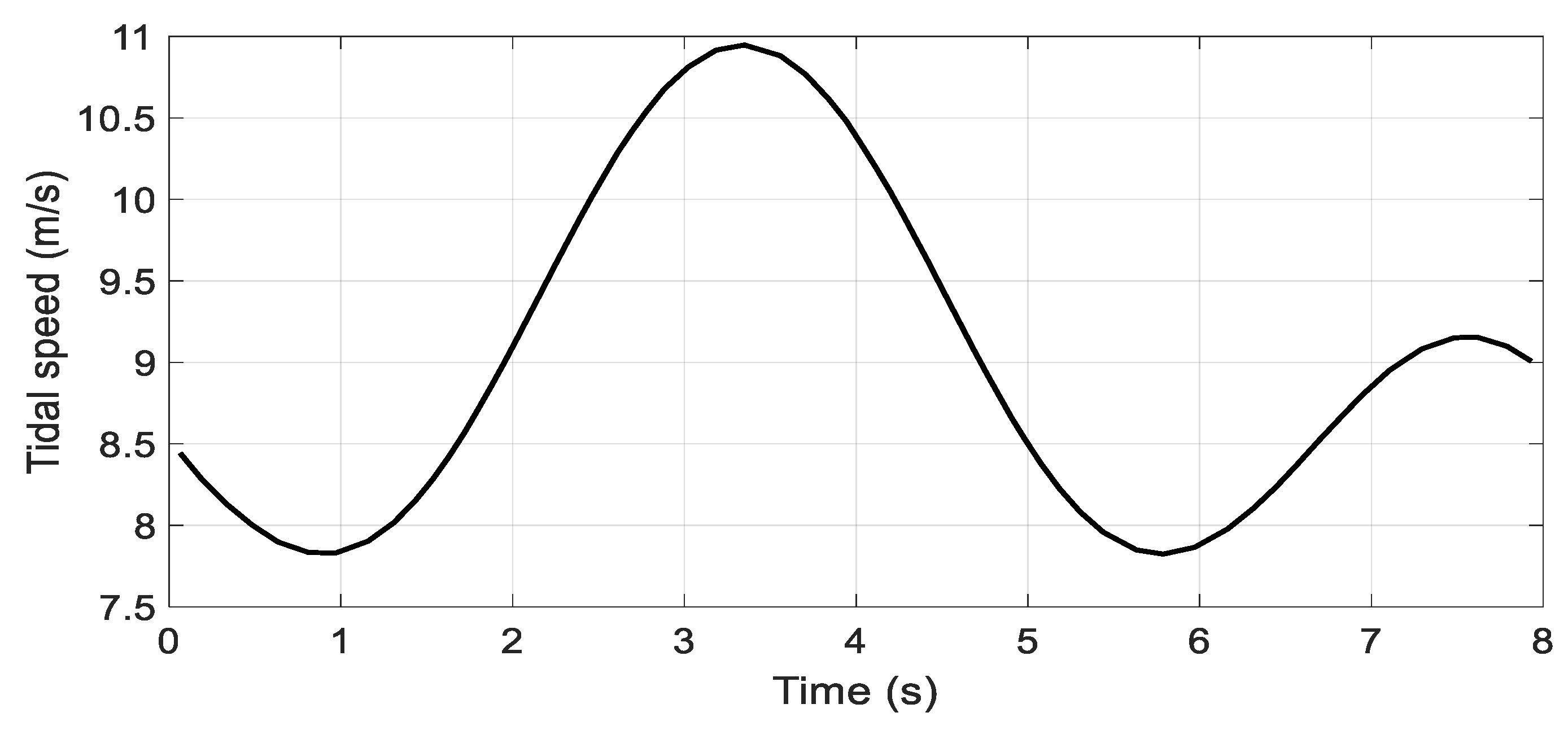
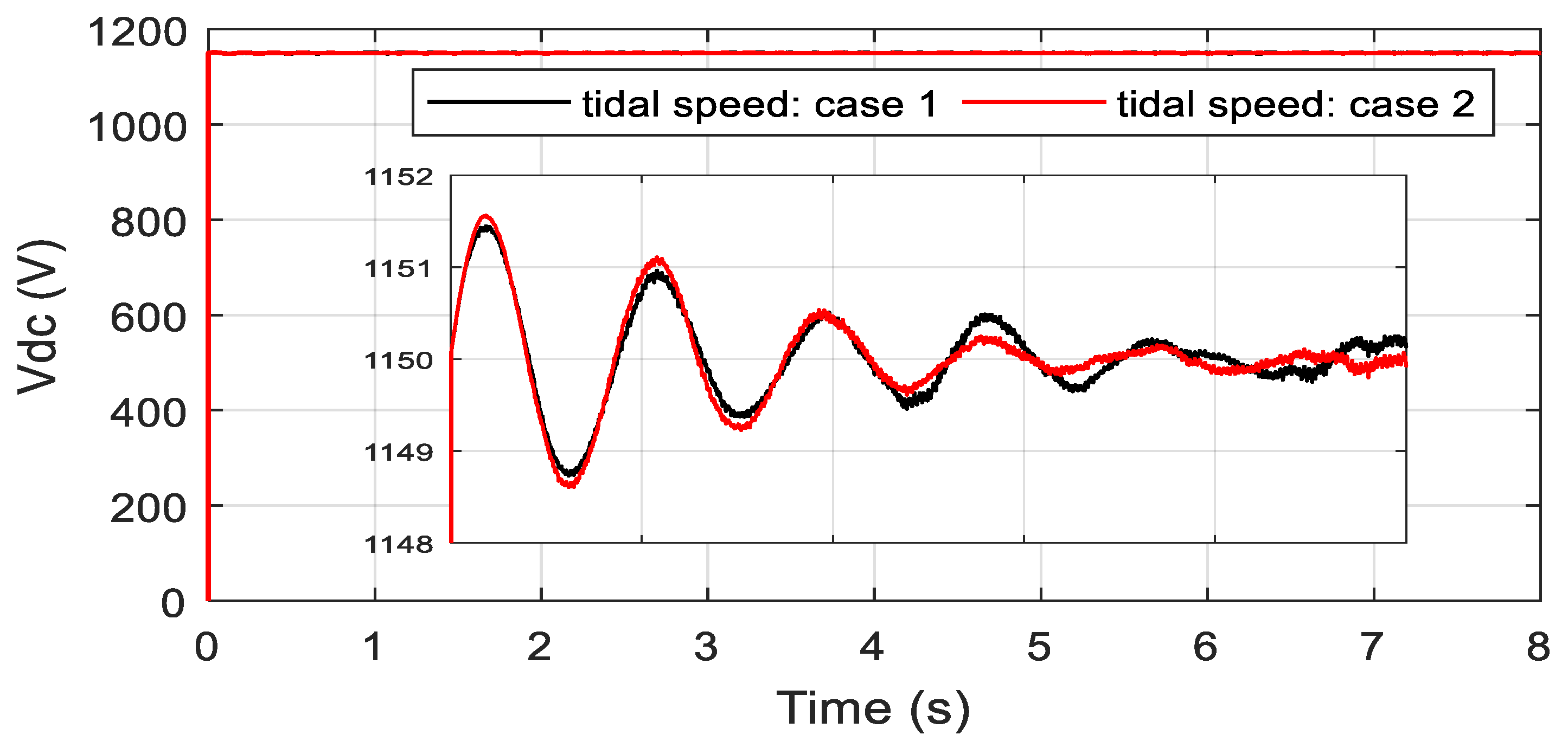
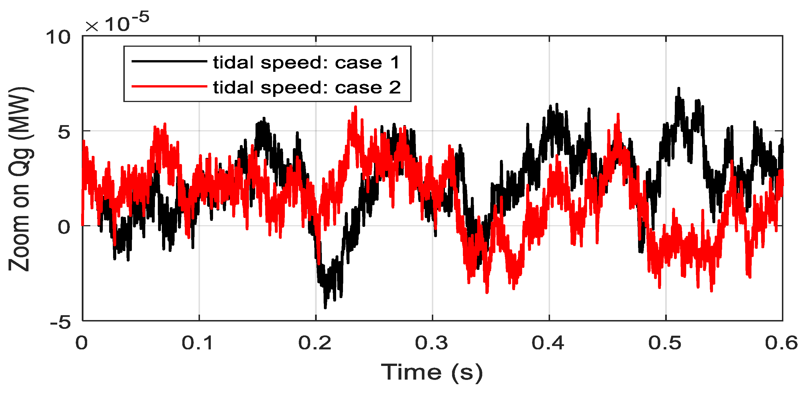
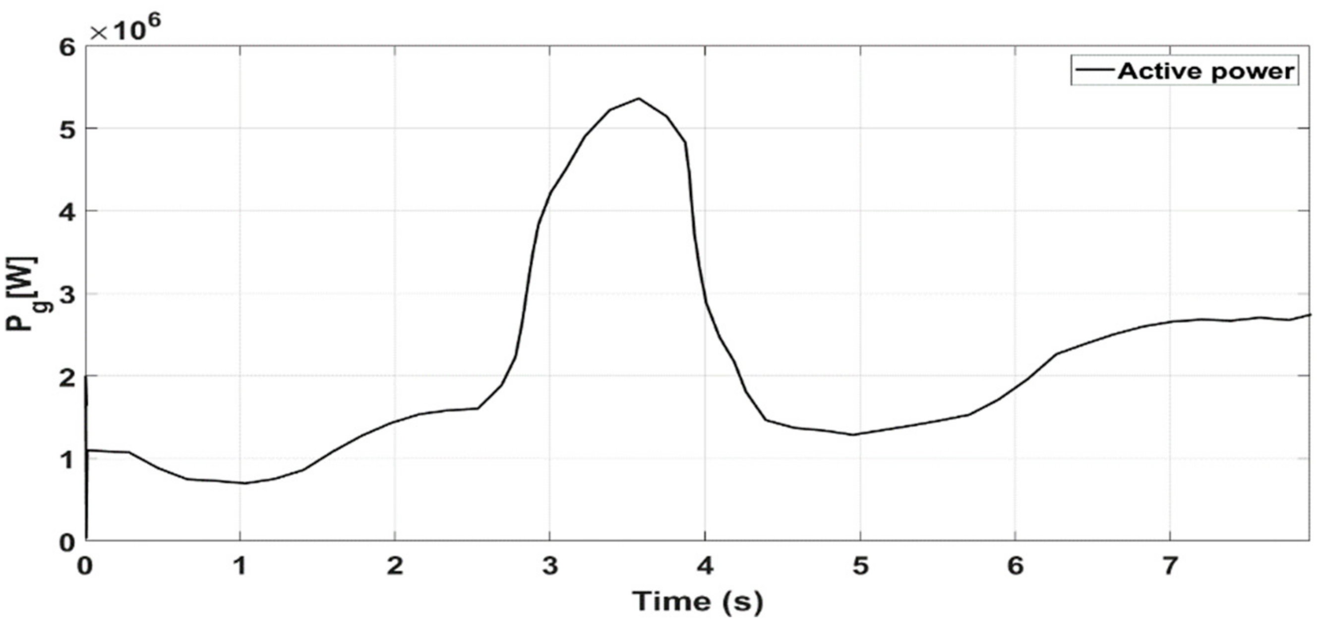
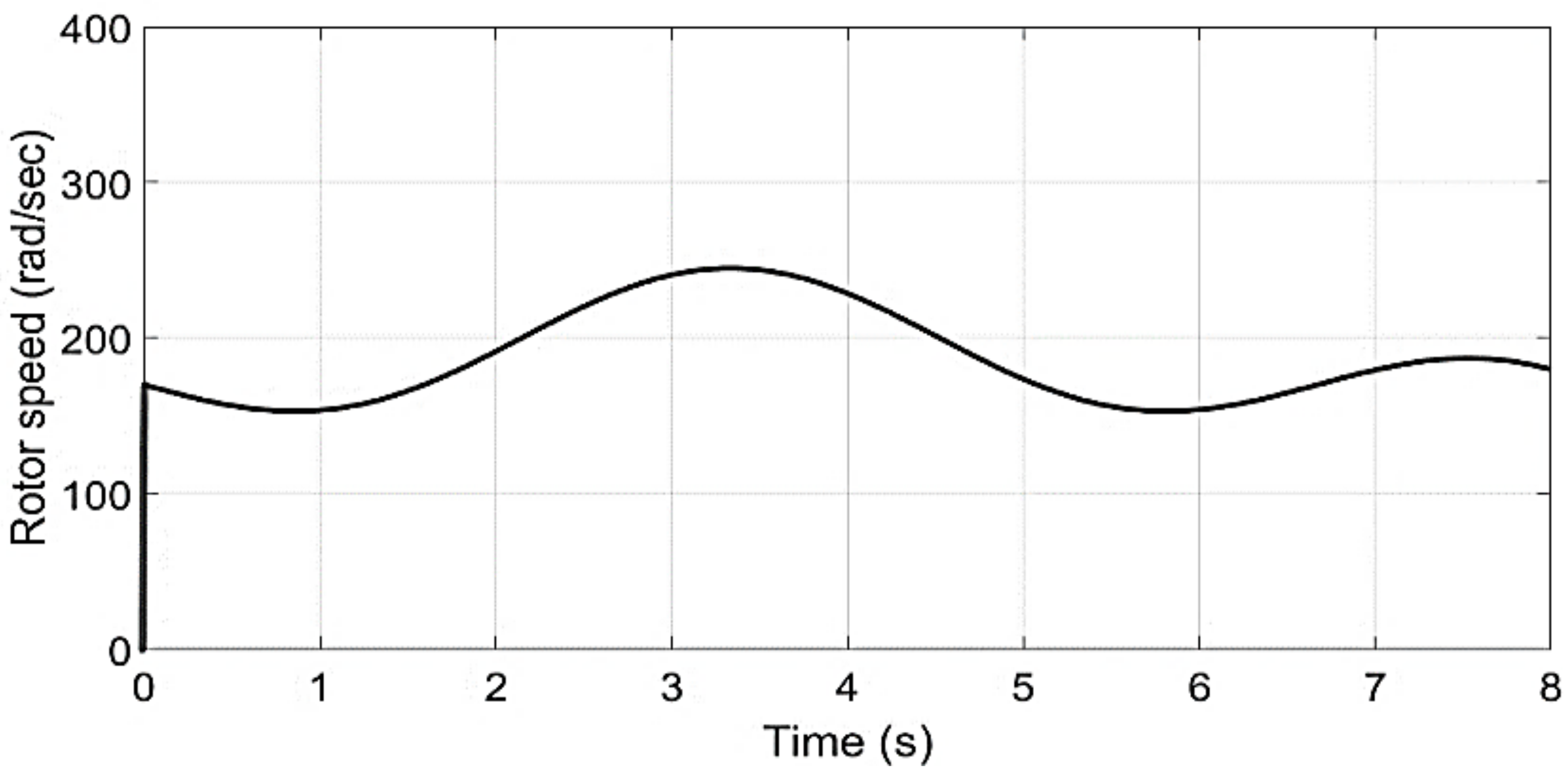
7.1. Fixed Parameters Analysis
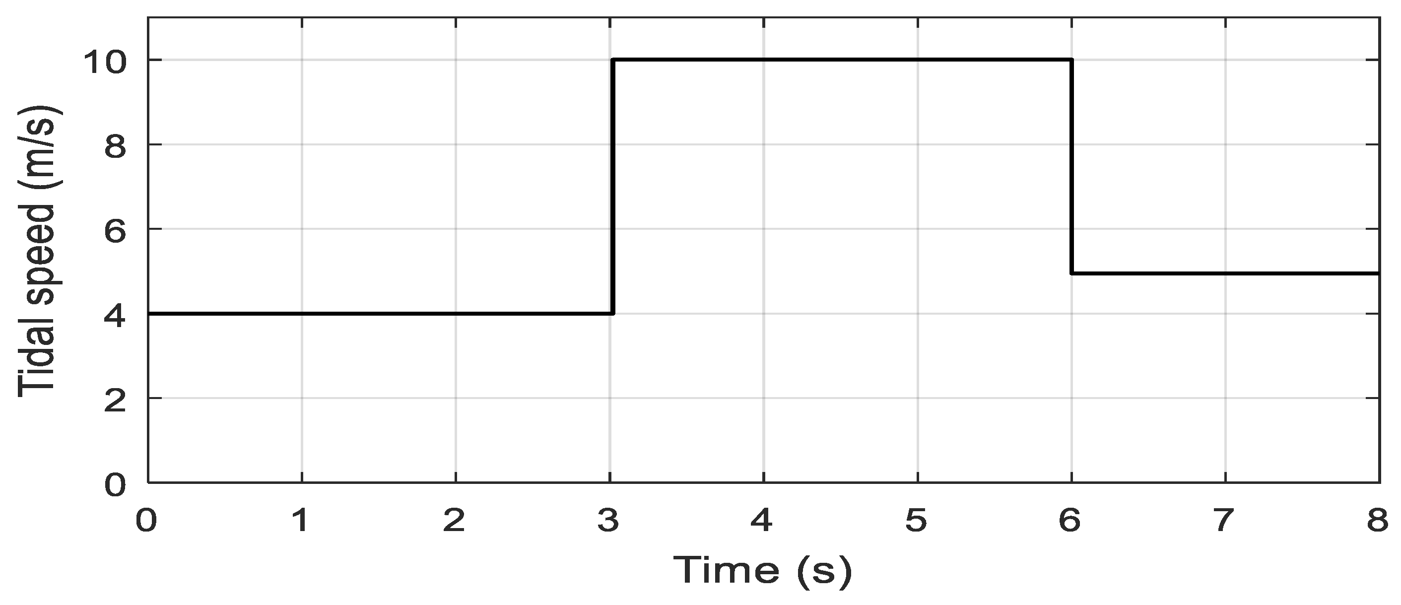
Case 1:
tidal speed with fast sudden variations
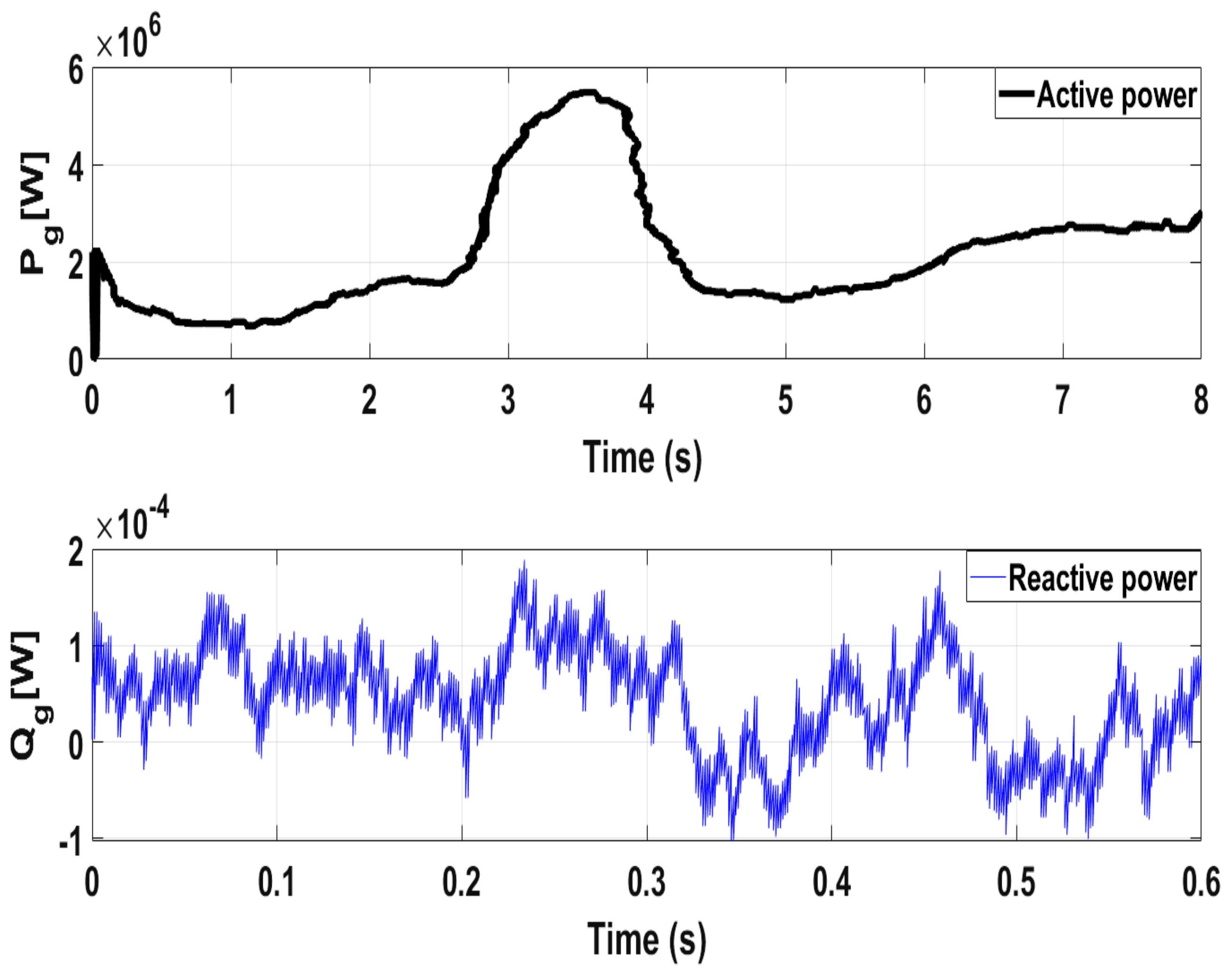
The simulated tidal velocity is shown by Figure 6. Figure 7 shows the electromagnetic toque with a perfect stabilized regime and fast convergence as compared to the SMC and PI strategies. It is worth mentioning that in the steady-state and with the proposed controller, the torque remains constant without any fluctuation. Figure 8 depicts the DC-link voltage tracking response and from the presented results it is obvious that, with the proposed controller, few transient oscillations are observed as compared to the SMC and PI controllers. Moreover, the settling time of the DC link voltage under the proposed controller scheme is shorter compared to the SMC and PI methods. Figure 9 represents the reactive power regulation, and it is well bounded with all three variants of control methods, i.e., the proposed control, the SMC, and PI. Furthermore, as can be seen, the proposed method is slightly better regarding the convergence criterion. Figure 10 shows active power response under the proposed SMC and PI control methods and from the presented results it is obvious that maximum active power is integrated into the grid using the proposed strategy.
Case 2:
Random tidal speed
In this case the simulated tidal speed is a new random profile shown in Figure 11. Figure 12 shows the electromagnetic toque tracking response under the proposed control method. From the given results it is obvious that the generated torque obtained is smooth and it follows the tidal speed profile. Figure 13 shows the DC-link voltage tracking response, and it can be observed from the presented results that the proposed controller provides almost the same response as in case 1. Figure 14 and Figure 15 show the reactive and active power responses and, from the results provided, it is evident that the speed profiles have no influence on the preferences of the proposed strategy. Figure 16 represents the rotational speed due to the random speed profile. Figure 17 clearly confirms that the turbine works at the optimal torque and extracts the maximum tidal power.
The above discussed results are summarized quantitatively and are listed in Table 3. From the quantitative comparisons, it can be concluded that, under fixed parameters, the proposed strategy successfully achieved the control objectives, with better performances than the mentioned conventional methods.

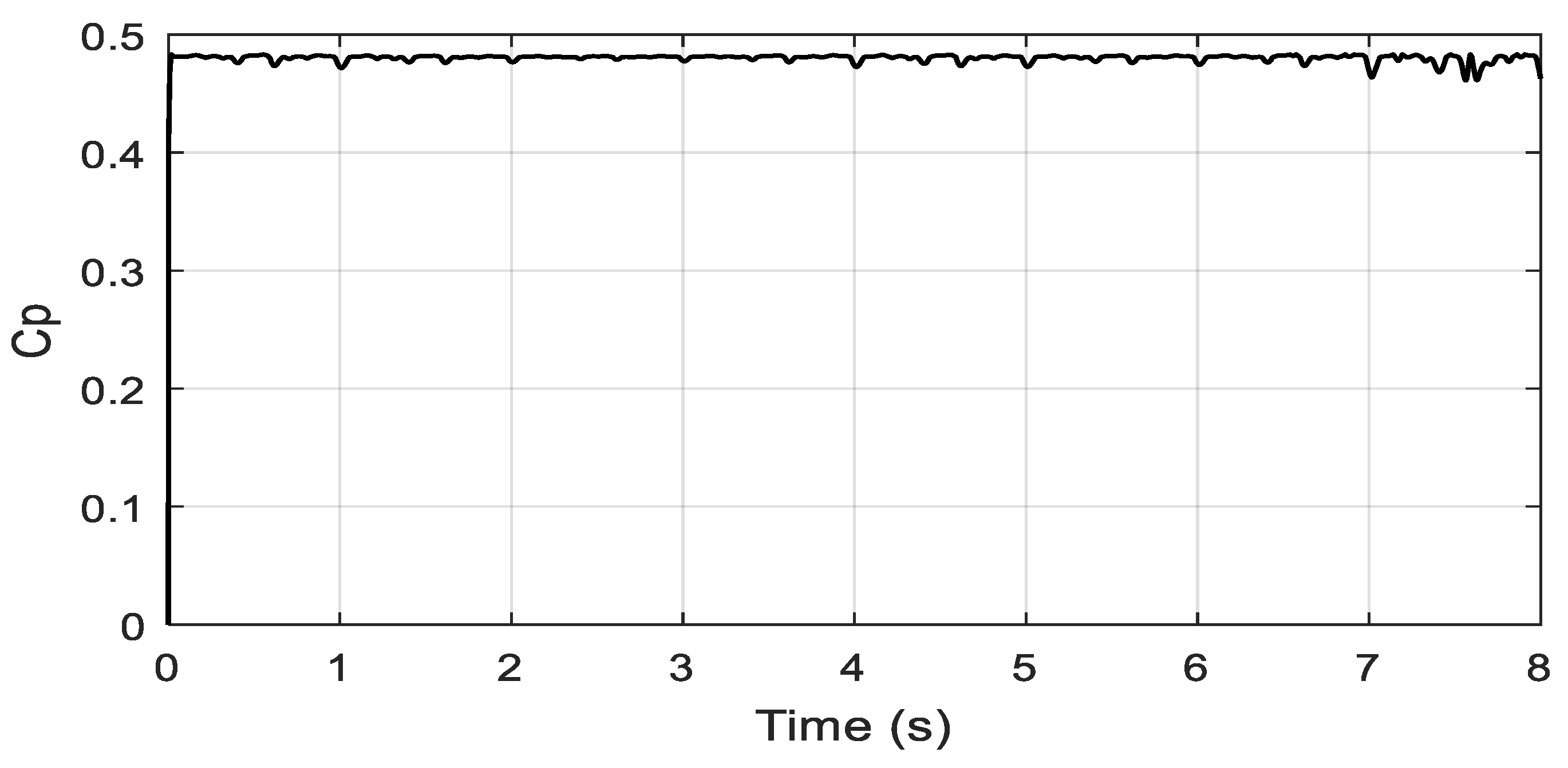
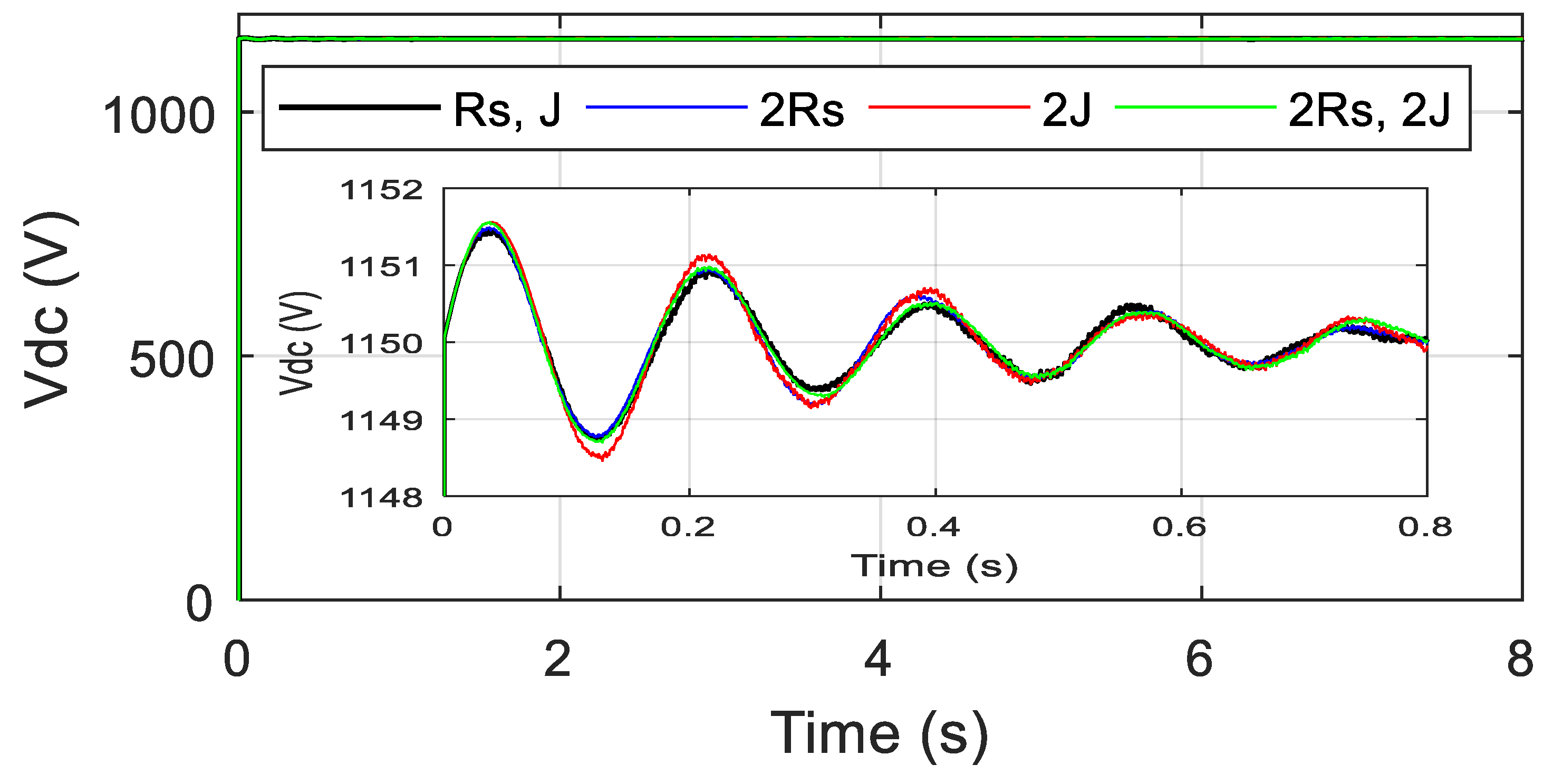
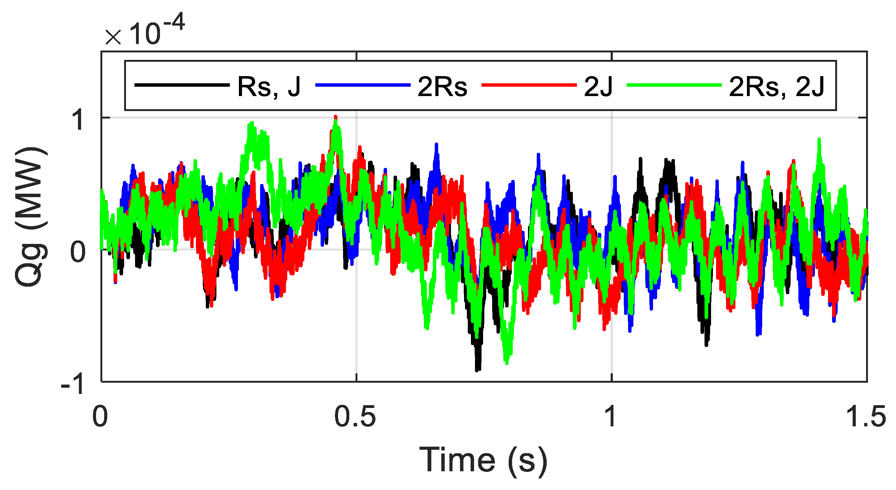
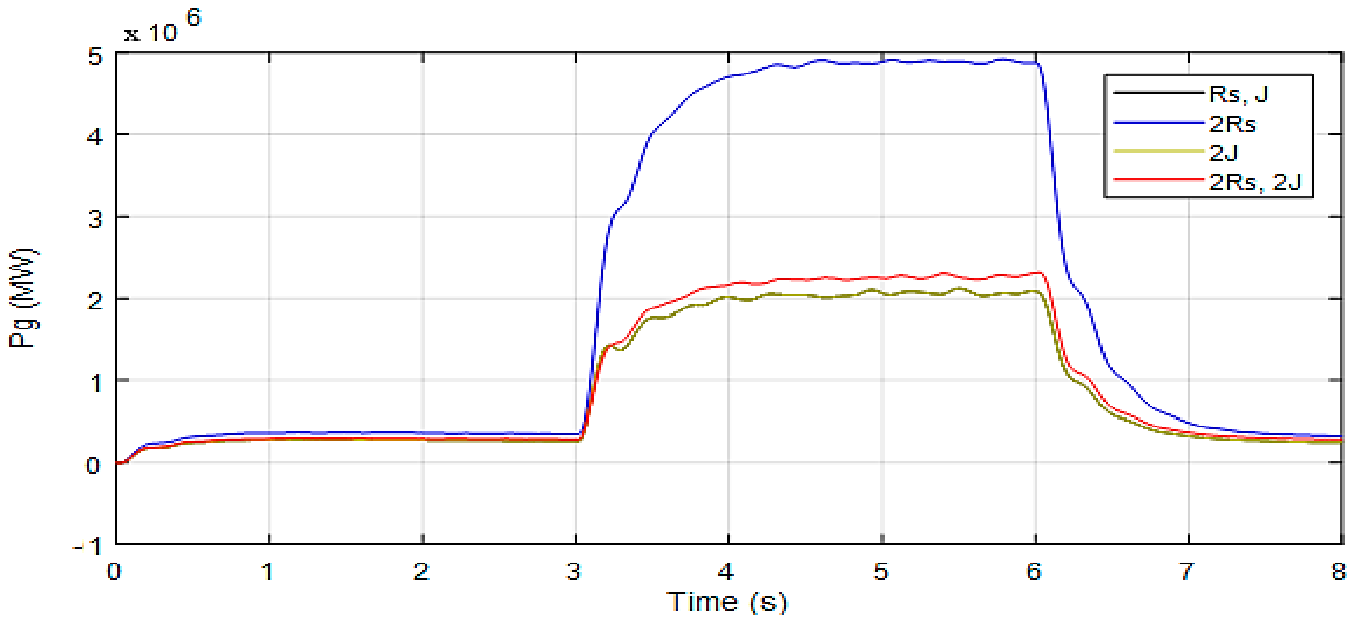
7.2. Robustenss Analysis

In this section the robustness of the proposed control method is verified, and the system is tested under parameter variations. A +100% of the stator resistance, +100% of the total inertia were simultaneously varied and the robustness test of the proposed controller for electromagnetic torque is presented in Figure 18. From the presented results, it is clear that the parameter variations do not influence the generated toque. Similar observations are recorded for the DC-link voltage tracking response given in Figure 19. Figure 20 also confirms the robustness of the proposed control method and the regulation error of reactive power is unchanged. Figure 21 shows the integrated active power to the grid and one can observe that, under parametric changes, the integrated power to the grid was not affected at all. In summary, the presented results confirm the robustness property of the proposed control scheme.

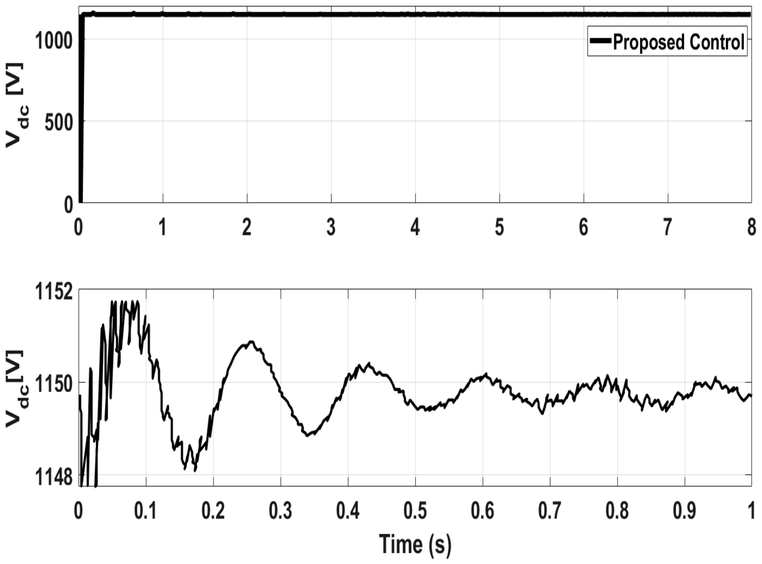
7.3. Processor in the Loop (PIL) Experimentation

Processor in the loop experimentation is a powerful tool which is utilized for validating the control system on a hardware processor, while the system plant is a software model. Thus, the control algorithm is tested in real time. More details about processor in the loop experimentation are reported in [28,29,30]. More importantly, the controller validated using PIL testing is equally efficient when it is tested on an actual hardware plant [28]. Thus, inspired from the above work, the proposed control schemes are tested using a processor in the loop (PIL) experiment and the block diagram of the setup is shown in Figure 22 and Figure 23. In the PIL experiment the digital signal processor (DSP) control card is physically integrated with the PMSG-based tidal conversion system model running in the Simulink environment. The studied conversion system is developed by using the SimPowerSystems blocks of the MTALAB/Simulink environment. The control schemes are implemented using a discrete time step of 5e−5 s. The control board consists of a dual core processor TMS320F379D which is programmed through the rapid prototyping method from the Simulink environment. Discrete versions of the discussed controllers are compiled from Simulink and the output or the hex file is programmed into the random access memory (RAM) of the processor. In the PIL experiment, the tidal turbine-based conversion system is not physical rather it is a Simulink environment, while the controller is working in real time. Data are exchanged between DSP control card and the software model using the high speed serial port.
Figure 24 shows the experimental response of the DC-link voltage. From the given results, it can be seen that the experimental results of the DC link voltage are very close to the numerical results shown in Figure 8. Figure 25 shows the active and reactive powers responses for test case1 and it closely matches the simulation responses of Figure 9 and Figure 10. Given the experimental results, it is clearly confirmed that the proposed controller can be released for real time implementation. Similarly, Figure 26 shows the active and reactive powers responses for test case2 and it closely matches the simulation responses of Figure 14 and Figure 15.

8. Conclusions

This article presents a novel adaptive passivity-based combined nonlinear observer–voltage control for a PMSG in Tidal a power conversion system through a fuzzy gains supervisor and high order sliding mode approaches. In comparison to other benchmark methods, the proposed strategy, exhibits the optimal performance for the maximum tidal power extraction, reactive power and DC-link voltage regulations. From the presented test cases, the robustness of the proposed control method is guaranteed. Furthermore, experimental validation has been conducted using a DSP control test bench. The experimental test confirms the feasibility of the proposed controller, where the results are very close to that provided by the numerical investigation.

Author Contributions

Conceptualization, Y.B. and N.U.; methodology, M.S.C.; software, Y.B.; validation, Y.B., A.A. and R.N.S.; formal analysis, N.U.; investigation, K.T.; resources, Y.B.; data curation, Y.B.; writing—original draft preparation, Y.B.; writing—review and editing, N.U.; M.S.C.; K.T. visualization, Y.B.; supervision, A.A.; project administration, A.A.; funding acquisition, N.U.; K.T. All authors have read and agreed to the published version of the manuscript.

Funding

This work was supported by Taif University Researchers Supporting Project number (TURSP-2020/144), Taif University, Taif, Saudi Arabia. This research was also supported by Grant 235 Number ENV6402012N from Prince of Songkla University.

Institutional Review Board Statement

Not applicable.

Informed Consent Statement

Not applicable.

Data Availability Statement

Author confirm the availability of all the supporting material and findings in the manuscript.

Acknowledgments

The authors acknowledge the funding support provided by Taif University Researchers Supporting Project number (TURSP-2020/144), Taif University, Taif, Saudi Arabia. Authors also acknowledge the Grant Number ENV6402012N from Prince of Songkla University.

Conflicts of Interest

The authors have no conflict of interest.

Appendix A. Proof of the Currents Error ε i Exponential Convergence

Consider Equation (14), which by the Rayleigh quotient and the matrix L α β positivity, guarantees the following inequality:
0 λ min L α β ε i 2 V f * ε i λ max L α β ε i 2  
where, λ max L α β and λ min L α β are the matrix L α β maximum and the minimum eigenvalues.
The time derivative of (14) along (A1) and (A2), which by the Rayleigh quotient and the dissipation term R α β + B i positivity, guarantees the following inequality:
V ˙ f * ε i = ε i T R α β + B i ε i λ min R α β + B i ε i 2 ,   t 0
where, λ min R α β + B i > 0 represents the matrix R α β + B i minimum eigenvalue. From (A1) and (A2), we deduce the following inequality:
V f * ˙ ε i = r 1 V f * ε i
where r 1 = λ min R α β + B i λ max L α β > 0 .
By integrating (A3), we obtain the following inequality:
V f * ˙ ε i V f * 0 e r 1 t
From A3 and A4 we obtain:
ε i   r 2 ε i e r 1 t
where r 2 = λ min L α β λ mix L α β > 0 .
Therefore, it can be deduced that with a rate of convergence r 1 the error ε i is exponentially decreasing.

Appendix B

Proof of the exponential stability of the speed tracking errors and the estimated current of the observer is given below.
Let us define the following desired Lyapunov function
V ob Ɛ = 1 2 Ɛ T D Ɛ
The time derivative of the function V ob Ɛ yields
V ˙ ob Ɛ = 1 2 Ɛ T W + K Ɛ
The observer estimated error Ɛ = 0 is asymptotically stable since K = K T > 0 .
Consider Equation (A8), which by the Rayleigh quotient and the matrix L α β positivity, guarantees the following inequality:
0 λ min L α β Ɛ 2 V ob Ɛ λ max L α β Ɛ 2  
The time derivative of (20) along (24) and (16), which by the Rayleigh quotient and the dissipation term W + K positivity, guarantees the following inequality:
V ˙ ob Ɛ = Ɛ T W + K Ɛ λ min W + K Ɛ 2 ,   t 0
where λ min W + K > 0 represents the matrix W + K minimum eigenvalue. From A8 and A9, we deduce the following inequality:
V ˙ ob Ɛ = r 3 V ob Ɛ
where r 1 = λ min W + K λ max L α β > 0 .
By integrating (A10) we obtain the following inequality:
V ˙ ob Ɛ V ob Ɛ 0 e r 3 t
From (A8) and (A11), we obtain:
Ɛ r 4 Ɛ e r 3 t
where r 3 = λ min W + K λ max L α β > 0 , and r 4 = λ min L α β λ mix L α β > 0 .
Then, it can be deduced that i ^ α β and ω ^ m of the observer are asymptotically stable.
Remark A1.
It is preferable to choose a high but limited value for this gain   b i , as it permits a good convergence rate of the parameter “ r 3 ” and to avoid divergence of   v α β . This limitation can be realized by simulation tests. The nonlinear observer can be shown as an optimal choice   b i = 250 .

References

  1. Zhou, Z.; Benbouzid, M.E.H.; Charpentier, J.F.; Scuiller, F.; Tang, T. Developments in large marine current turbine technologies—A Review. Renew. Sustain. Energy Rev. 2017, 71, 852–858. [Google Scholar] [CrossRef]
  2. Guo, B.; Wang, D.; Zhou, J.; Shi, W.; Zhou, X. Performance evaluation of a submerged tidal energy device with a single mooring line. Ocean Eng. 2020, 196, 106791. [Google Scholar] [CrossRef]
  3. Belkhier, Y.; Achour, A.Y. Fuzzy passivity-based linear feedback current controller approach for PMSG-based tidal turbine. Ocean Eng. 2020, 218, 108156. [Google Scholar] [CrossRef]
  4. Yin, X.; Lei, M.; Pan, H. Direct optimal power extraction control for a tidal turbine system based on fuzzy power tuning. Ocean Eng. 2018, 170, 426–433. [Google Scholar] [CrossRef]
  5. Belkhier, Y.; Achour, A.Y. Passivity-based voltage controller for tidal energy conversion system with permanent magnet synchronous generator. Int. J. Control Autom. Syst. 2020, 19, 1–11. [Google Scholar] [CrossRef]
  6. Toumi, S.; Elbouchikhi, E.; Amirat, Y.; Benbouzid, M.; Feld, G. Magnet failure-resilient control of a direct-drive tidal turbine. Ocean Eng. 2019, 187, 106207. [Google Scholar] [CrossRef]
  7. Gu, Y.-J.; Yin, X.-X.; Liu, H.-W.; Li, W.; Lin, Y.-G. Fuzzy terminal sliding mode control for extracting maximum marine current energy. Energy 2015, 90, 258–265. [Google Scholar] [CrossRef]
  8. Othman, A.M. Enhancement of tidal generators by superconducting energy storage jaya-based sliding-mode con-troller. Int. J. Energy Res. 2020, 44, 11658–11675. [Google Scholar] [CrossRef]
  9. Zhou, Z.; Elghali, B.S.; Benbouzid, M.E.H.; Amirat, Y.; Elbouchikhi, E.; Feld, G. Tidal stream turbine control: An active disturbance rejection control approach. Ocean Eng. 2020, 202, 107190. [Google Scholar] [CrossRef]
  10. Yin, X.; Zhao, X. ADV Preview based nonlinear predictive control for maximizing power generation of a tidal turbine with hydrostatic transmission. IEEE Trans. Energy Convers. 2019, 34, 1781–1791. [Google Scholar] [CrossRef]
  11. Yin, X.; Zhao, X. Sensorless maximum power extraction control of a hydrostatic tidal turbine based on adaptive extreme learning machine. IEEE Trans. Sustain. Energy 2020, 11, 426–435. [Google Scholar] [CrossRef]
  12. Gaamouche, R.; Redouane, A.; El harraki, I.; Belhorma, B.; El hasnaoui, A. Optimal feedback control of nonlinear var-iable-speed marine current turbine using a Two-Mass model. J. Mar. Sci. Appl. 2020, 19, 83–95. [Google Scholar] [CrossRef]
  13. Moon, S.H.; Park, B.G.; Kim, J.W.; Kim, J.M. Maximum power-point tracking control using perturb and observe algo-rithm for tidal current generation system. Int. J. Precis. Eng. Manuf. Green Technol. 2020, 7, 849–858. [Google Scholar] [CrossRef]
  14. Sahu, P.C.; Baliarsingh, R.; Prusty, R.C.; Panda, S. Novel DQN optimized tilt fuzzy cascade controller for frequency stability of a tidal energy based AC Microgrid. Int. J. Ambient Energy 2020, 1–13. [Google Scholar] [CrossRef]
  15. Yang, B.; Wu, Q.H.; Tiang, L.; Smith, J.S. Adaptive passivity-based control of a TCSC for the power system damp-ing improvement of a PMSG based offshore wind farm. In Proceedings of the IEEE International Conference on Renewable Energy Research and Applications ICRERA-2013, Madrid, Spain, 20–23 October 2013; pp. 1–5. [Google Scholar]
  16. Achour, A.Y.; Mendil, B.; Bacha, S.; Munteanu, I. Passivity-based current controller design for a permanent-magnet synchronous motor. ISA Trans. 2009, 48, 336–346. [Google Scholar] [CrossRef]
  17. Subramaniam, R.; Joo, Y.H. Passivity-Based Fuzzy ISMC for Wind Energy Conversion Systems With PMSG. IEEE Trans. Syst. Man Cybern. 2021, 51, 2212–2220. [Google Scholar] [CrossRef]
  18. Yang, B.; Yu, H.; Zhang, Y.; Chen, J.; Sang, Y.; Jing, L. Passivity-based sliding-mode control design for optimal power extraction of a PMSG based variable speed wind turbine. Renew. Energy 2018, 119, 577–589. [Google Scholar] [CrossRef]
  19. Zhou, Z.; Scuiller, F.; Charpentier, J.F.; Benbouzid, M.E.H.; Tang, T. Power smoothing control in a grid-connected marine current turbine system for compensating swell effect. IEEE Trans. Sustain. Energy 2013, 4, 816–826. [Google Scholar] [CrossRef] [Green Version]
  20. Yang, B.; Yu, T.; Shu, H.; Qiu, D.; Zhang, Y.; Cao, P.; Jiang, L. Passivity-based linear feedback control of permanent magnetic synchronous generator-based wind energy conversion system: Design and analysis. IET Renew. Power Gener. 2018, 12, 981–991. [Google Scholar] [CrossRef] [Green Version]
  21. Gonzalez, W.G.; Garces, A.; Fosso, A.O.B. Passivity-Based Control for Small Hydro-Power Generation With PMSG and VSC. IEEE Access 2020, 8, 153001–153010. [Google Scholar] [CrossRef]
  22. David, F.M.; Ortega, R. Adaptive passivity-based control for maximum power extraction of stand-alone windmill systems. Control Eng. Pract. 2012, 20, 173–181. [Google Scholar] [CrossRef]
  23. Cisneros, R.; David, F.M.; Ortega, R. Passivity-based control of a grid-connected small-scale windmill with limited control authority. IEEE J. Emerg. Sel. Top. Power Electron. 2013, 1, 247–259. [Google Scholar] [CrossRef]
  24. Hosseinzadeh, M.; Yazdanpanah, M.J. Robust adaptive passivity-based control of open-loop unstable affine non-linear systems subject to actuator saturation. IET Control Theory Appl. 2017, 11, 2731–2742. [Google Scholar] [CrossRef]
  25. Ghefiri, K.; Garrido, I.; Garrido, A.J.; Bouallègue, S.; Haggègs, J. Fuzzy gain scheduling of a rotational speed control for a tidal stream generator. In Proceedings of the 2018 International Symposium on Power Electronics, Electrical Drives, Automation and Motion (SPEEDAM), Amalfi, Italy, 20–22 June 2018; pp. 1003–1008. [Google Scholar]
  26. Lee, M.A.; Takagi, H. Dynamic control of genetic algorithms using fuzzy logic techniques. In Proceedings of the International Conference on Genetic Algorithms, San Mateo, CA, USA, 17–21 July 1993; pp. 76–83. [Google Scholar]
  27. Yubazaki, N.; Otami, M.; Ashid, T.; Hirota, K. Dynamic fuzzy control method and its application to positioning of induction motor. In Proceedings of the Fourth IEEE International Conference on Fuzzy Systems, Yokohama, Japan, 20–24 March 1995; pp. 1095–1102. [Google Scholar]
  28. Ullah, N.; Farooq, Z.; Sami, I.; Chowdhury, M.S.; Techato, K.; Alkhammash, H.I. Industrial Grade Adaptive Control Scheme for a Micro-Grid Integrated Dual Active Bridge Driven Battery Storage System. IEEE Access 2020, 8, 210435–210451. [Google Scholar] [CrossRef]
  29. Ullah, N.; Sami, I.; Chowdhury, M.S.; Techato, K.; Alkhammash, H. Artificial Intelligence Integrated Fractional Or-der Control of Doubly Fed Induction Generator-Based Wind Energy System. IEEE Access 2021, 9, 5734–5748. [Google Scholar] [CrossRef]
  30. Ullah, N.; Ullah, A.; Ibeas, A.; Herrera, J. Improving the Hardware Complexity by Exploiting the Reduced Dynam-ics-Based Fractional Order Systems. IEEE Access 2017, 5, 7714–7723. [Google Scholar] [CrossRef]
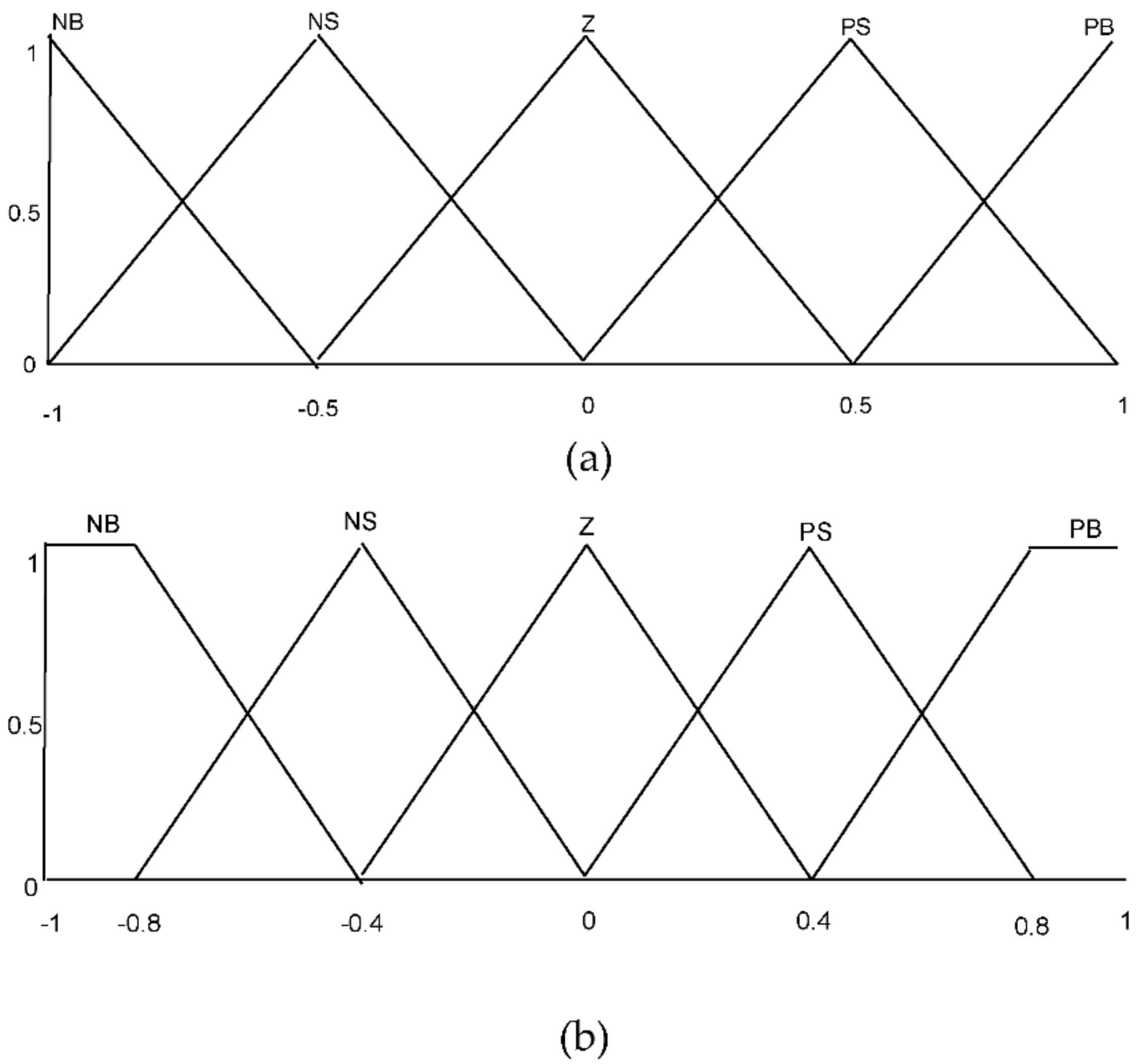
Figure 1. Tidal conversion system under Simulink.
Sustainability 13 03737 g001
Figure 2. Proposed Strategy design.
Sustainability 13 03737 g002
Figure 3. Desired torque design with the fuzzy supervisory-high order sliding mode controller (FS-HSMC).
Sustainability 13 03737 g003
Figure 4. The fuzzy controller configuration. (a) Inputs function (b) outputs function.
Sustainability 13 03737 g004
Figure 5. Grid-side converter (GSC) Proportional Integral (PI) controller schemas.
Sustainability 13 03737 g005
Figure 6. Tidal speed.
Sustainability 13 03737 g006
Figure 7. Electromagnetic torque.
Sustainability 13 03737 g007
Figure 8. DC-link voltages.
Sustainability 13 03737 g008
Figure 9. Zoom on Reactive power.
Sustainability 13 03737 g009
Figure 10. Active power.
Sustainability 13 03737 g010
Figure 11. Random tidal speed.
Sustainability 13 03737 g011
Figure 12. Electromagnetic torque.
Sustainability 13 03737 g012
Figure 13. DC-link voltage responses.
Sustainability 13 03737 g013
Figure 14. Reactive power.
Sustainability 13 03737 g014
Figure 15. Active power.
Sustainability 13 03737 g015
Figure 16. Rotor speed.
Sustainability 13 03737 g016
Figure 17. Power coefficient.
Sustainability 13 03737 g017
Figure 18. Electromagnetic torque with parameter changes.
Sustainability 13 03737 g018
Figure 19. DC-link voltage with parameter changes.
Sustainability 13 03737 g019
Figure 20. Zoom reactive power with parameter changes.
Sustainability 13 03737 g020
Figure 21. Active power with parameter changes.
Sustainability 13 03737 g021
Figure 22. Experimental digital signal processor (DSP) Board.
Sustainability 13 03737 g022
Figure 23. Experimental Step.
Sustainability 13 03737 g023
Figure 24. Experimental DC-link responses.
Sustainability 13 03737 g024
Figure 25. Experimental Active and Reactive power responses case1.
Sustainability 13 03737 g025
Figure 26. Experimental Active and Reactive power Response Case 2.
Sustainability 13 03737 g026
Table 1. Fuzzy logic rules of k Fp and k Fi .
ε m NBNSZPSPB
Δ ε m
NBNBNBNBNSZ
NSNBNSNSNSZ
ZNBNSZPSPB
PSZPSPSPSPB
PBZPSPBPBPB
Negative Big (NB), Negative Small (NS), Zero (Z), Positive Big (PB), and Positive Small (PS).
Table 2. System parameters.
PMSG (Permanent Magnet Synchronous Generator Parameter)Value
Water density ( ρ ) 1024 kg/m2
Stator resistance ( R s )0.006 Ω
Tidal turbine radius ( R )3.1 m
Stator inductance ( L d q )0.3 mH
Pole pairs number ( p )48
Flux linkage ( ψ f )1.48 Wb
Total inertia ( J )35,000 kg·m2
DC-link capacitor (C)
Grid voltage ( V g )
2.9 F
574 V
DC-link voltage ( V d c )1150 V
Grid-filter resistance ( R f )0.3 pu
Grid-filter inductance ( L f )0.3 pu
Table 3. Performance comparisons of the tested controls.
ControlsProposedSMC (Sliding-Mode Control)PI (Proportional Integral)
Convergence speedVery fast (0.8e−3 s)Fast (1.2e−3 s)Slow (2e−3 s)
Stability Very stable (fluctuations free)Stable (with fluctuations)Poor stability (with fluctuations)
Robustness High robustnessNot robust Not robust
PerformanceHigherlowlow
Publisher’s Note: MDPI stays neutral with regard to jurisdictional claims in published maps and institutional affiliations.

