Article

Optimal Operation of a Hydrogen Storage and Fuel Cell Coupled Integrated Energy System

School of Engineering, Cardiff University, Queen’s Buildings, The Parade, Cardiff CF24 3AA, Wales, UK
*
Author to whom correspondence should be addressed.
Sustainability 2021, 13(6), 3525; https://doi.org/10.3390/su13063525
Submission received: 9 February 2021 / Revised: 11 March 2021 / Accepted: 12 March 2021 / Published: 22 March 2021
(This article belongs to the Special Issue Sustainable Hydrogen Energy Systems: Electric Applications)

Abstract

:
Integrated energy systems have become an area of interest as with growing energy demand globally, means of producing sustainable energy from flexible sources is key to meet future energy demands while keeping carbon emissions low. Hydrogen is a potential solution for providing flexibility in the future energy mix as it does not emit harmful gases when used as an energy source. In this paper, an integrated energy system including hydrogen as an energy vector and hydrogen storage is studied. The system is used to assess the behaviour of a hydrogen production and storage system under different renewable energy generation profiles. Two case studies are considered: a high renewable energy generation scenario and a low renewable energy generation scenario. These provide an understanding of how different levels of renewable penetration may affect the operation of an electrolyser and a fuel cell against an electricity import/export pricing regime. The mathematical model of the system under study is represented using the energy hub approach, with system optimisation through linear programming conducted via MATLAB to minimise the total operational cost. The work undertaken showcases the unique interactions the fuel cell has with the hydrogen storage system in terms of minimising grid electricity import and exporting stored hydrogen as electricity back to the grid when export prices are competitive.

1. Introduction

Hydrogen is a possible solution for the decarbonisation of energy systems as it can be produced through zero-carbon renewable energy generation. Hydrogen itself, when used as an energy source, does not release CO2. At present, around 95% of the hydrogen produced throughout the world uses a chemical process called steam methane reformation [1]. Given that this process heavily relies on the use of fossil fuels, the case for producing hydrogen through an integrated energy system running on renewable resources such as wind and solar photovoltaics (PV) becomes attractive. For instance, the findings in [2] provide evidence for the possibility of green hydrogen production in Europe, as 88% of the regions with these capabilities have sufficient renewable energy resources. Significant insight towards fulfilling this potential can be gained through the comprehensive analyses of integrated energy systems considering hydrogen.
One of the main reservations of producing hydrogen from renewables is its cost. The low round trip efficiency of energy conversion causes significant energy and economic losses. Thus, for integrated energy systems geared for hydrogen production to have similar profitability as wind or solar PV systems, the selling price of electricity must be significantly high [3]. However, the continuously decreasing cost of renewable energy generation due to the fall in the cost of the technology itself is encouraging the use of hydrogen in the energy mix.
The case for hydrogen storage in integrated energy systems is compelling as it allows for greater system flexibility. Hydrogen can be stored for the provision of balancing services if there is a mismatch in electricity supply and demand. Hence, stored hydrogen becomes a sustainable source of dispatchable energy, reducing the reliance of having to import grid electricity, which may be produced from non-renewable energy sources. It can also be used to provide fuel to hydrogen vehicles. Hydrogen also has a low discharge rate and can store larger amounts of energy compared to other energy storage systems, such as batteries and compressed air energy storage [4].
There are numerous references in the literature studying integrated energy systems including hydrogen. For instance, [5,6,7] demonstrate the cost optimal operation of hydrogen-coupled integrated energy systems using the concept of energy hub, which enables a steady-state analysis of the systems under study. However, in these references, hydrogen is a biproduct of excess electricity generation as hydrogen demand is not defined. Thus, an understanding of how the integrated energy system could optimally dispatch hydrogen as an energy vector either for storage or direct consumption cannot be established.
An example of a system linking electricity, gas, and hydrogen as energy vectors is presented in [8]. An optimal energy flow problem formulation is employed to assess hydrogen economy issues such as production, distribution, and utilisation. Reference [9] showcases an integrated energy system including hydrogen and electricity as energy vectors. A hydrogen storage system and a fuel cell are considered. The problem is formulated as a mixed integer linear programming (MILP) optimisation problem, which is used to demonstrate what the model can do for the optimal management of the system. The mathematical modelling approach used in both references is based on energy hub modelling. However, [8] does not account for energy storage, and neither of these references look at electrolyser input and fuel cell output against electricity export and import prices.
Reference [9] demonstrates that introducing hydrogen into an integrated energy system allows for a higher penetration of renewable energy generation. Along the same line, [10] presents a study of an integrated energy system, which uses hydrogen for seasonal storage and assesses its variation depending on season. However, as opposed to [11], the optimisation exercise in [12] considers a fully renewable energy run system which is isolated from the main electrical grid supply. Furthermore, a buy-back period using operational, maintenance, and installation costs is considered. The robust scheduling of an integrated energy system is presented in [13], where it is found that operational costs are decreased by up to 7.8% when hydrogen is included. Similarly, an integrated energy system considering hydrogen is studied for optimisation in [14]. However, in both [13] and [14], the systems under study do not consider the use of fuel cells and, in addition, they look at a time scale of 24 h only, which may not be sufficient to provide a detailed assessment of system behaviour. Furthermore, reference [15] states that for hydrogen systems to be economically viable, they must have greater utilisation times. Hence, the more renewable energy available, the greater the utilisation times would be—resulting in a marked difference in the system’s total operational cost.
An essential reason for adding hydrogen into integrated energy systems as a means of energy storage is to avoid curtailment of renewable energy generation and, thus, maximise its potential. This is successfully demonstrated in [16,17]. This also allows for the energy system to be almost fully run with renewable energy only. However, the findings in [18] are important, as it is shown that the stored hydrogen available for conversion via a fuel cell cannot meet annual shortcomings in electrical supply. This causes the system to import 70% of electricity to make up for the shortcomings.
Reference [19] studies an integrated energy system used to charge a fleet of electric vehicles. The main idea behind the presented work is to assess the optimal dispatch of the available energy source for vehicle refuelling. A similar idea is demonstrated in [20], thus providing insight on the practical use of renewable energy resources for vehicle refuelling, where hydrogen is a biproduct of stored overgeneration. A hydrogen vehicle refuelling system within an integrated energy system is presented in [21], but there is no historical data available for comparison. All references mentioned in this paragraph are relevant as they involve the optimal management of renewable energy sources, where the energy hub is used as the modelling approach.
An important challenge faced by integrated energy systems is component sizing. Reference [22] looks at the optimal sizing and operational optimisation of an off-grid integrated energy system fully running on renewable energy. Similarly, for grid-connected systems featuring hydrogen, it is paramount to assess the suitability of the on-site renewable generation capacity and hydrogen storage and conversion systems. This helps determine the best way to operate the system and optimal system sizing to achieve 100% renewable energy generation.
In integrated energy systems, flexibility offers key advantages. For instance, the inclusion of hydrogen and hydrogen storage can help achieve an optimal system operation guaranteeing 100% renewable energy generation [9,23], which may be more challenging in systems only considering electrical energy storage. Reference [24] also looks at optimising the operation of an integrated energy system with hydrogen to achieve 100% renewable energy generation. However, a 24-h window is assessed in [24] only and as discussed previously, a longer optimisation horizon would be needed not only to fully understand system behaviour, but also to assess the ability of the system to conduct day-ahead scheduling. Day-ahead scheduling is important as it accounts for the uncertainty of intermittent renewable energy generation whilst still meeting energy demand.
References [20,25] are of great value, as they report work on practical projects where optimal system operation is addressed and historical data is used. They also provide insight into best practice in terms of the operation, sizing, and the cost minimisation of integrated energy systems featuring hydrogen.
Although the references discussed so far in the previous paragraphs provide a good understanding of integrated energy systems featuring hydrogen as an energy vector, the role that storage can have alongside the use of electrolysers and fuel cells deserves further attention. For instance, for an energy system considering renewable sources, energy could be suitably stored instead of being curtailed. From a practical standpoint, the behaviour of import and export prices of electricity could be considered to calculate buy-back periods. In addition, the use of hydrogen over a sustained period of time beyond a 24-h window, for both meeting hydrogen demand (e.g., hydrogen fuelled vehicles) and as a source for electricity generation, could be useful for an optimal day-ahead scheduling of hydrogen supply in a system.
In this paper, a grid-connected integrated energy system considering renewable electricity generation, hydrogen storage, and a fuel cell is studied. The main objective of this work is to demonstrate the use of hydrogen storage for electricity demand balancing, as well as fuel provision for a fleet of hydrogen fuelled vehicles. This is formulated as an optimal dispatch problem based on two main scenarios depicting variance of renewable energy generation and energy demand with respect to winter and summer seasons. Historical data is used from an existing integrated energy system in Scotland, enabling to accurately assess the operational behaviour of hydrogen storage and of the fuel cell. The consideration of import and export prices of electricity during system optimisation provides insight as to how the hydrogen storage system and fuel cell help satisfy energy demands while keeping total operational cost at a minimum. Total operational cost minimisation is expected to be achieved by maximising the usage of on-site renewable energy generation and hydrogen storage. This is considered a sustainable approach of operation as it minimises grid electricity imports to meet electricity demand and enables running the system almost fully on renewable energy.

2. Materials and Methods

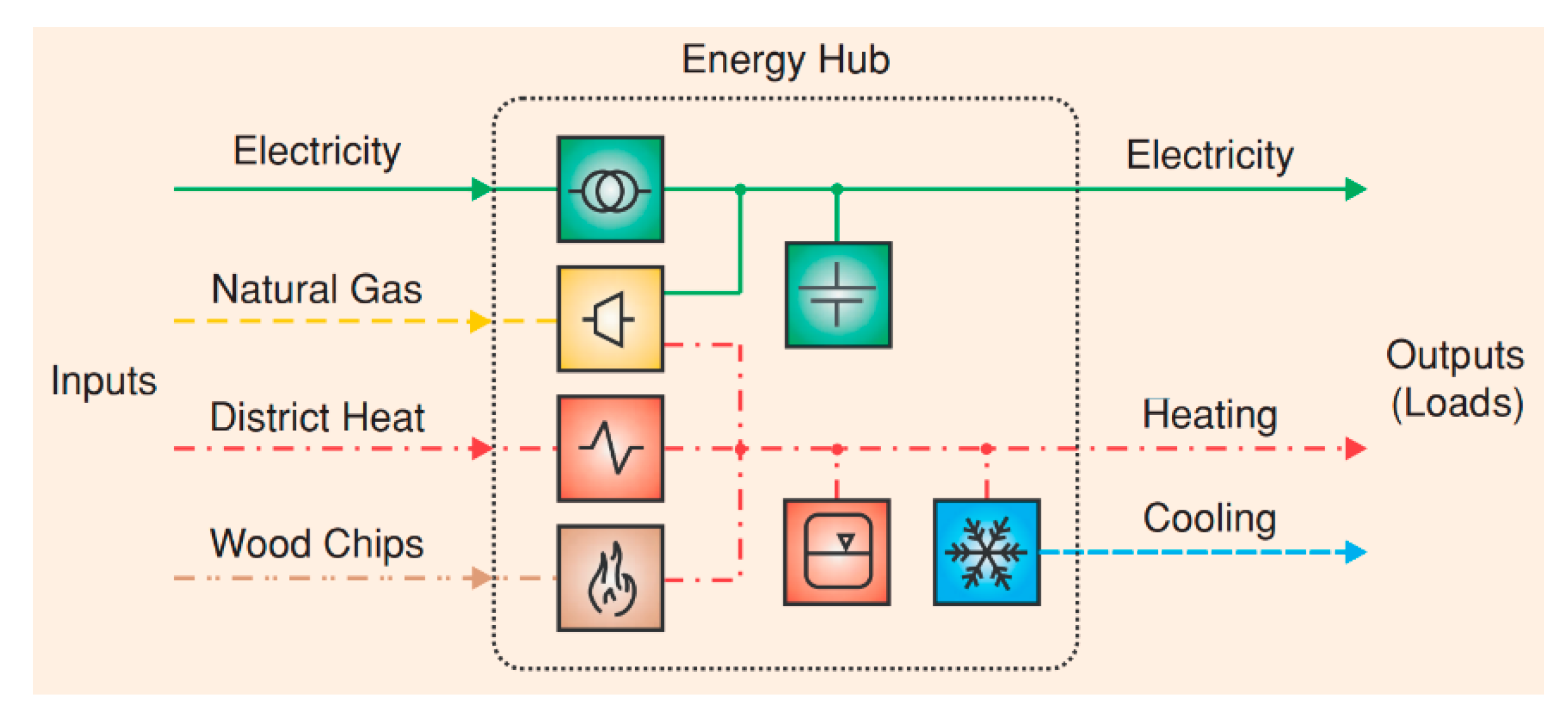
2.1. Energy Hub Modelling Approach

The modelling approach used in this paper is based on energy hub representations. This method allows for a steady-state representation of an integrated energy system by observing the conversion of a specific type of input energy in order to fulfil a specific load demand within a network that has different power delivery routes [15,26]. An example of an energy hub is shown in Figure 1.
As seen in Figure 1, the energy hub consists of input energy vectors, which can either be stored or converted (for example, heat energy from district heat is converted to a cooling energy output via an electric chiller) and released as output energy of a different form. In general, energy hubs comprise of three main elements [27]: direct connections, converters, and storage devices.
The direct connection serves the purpose of transporting an input energy vector to the output (demand/load) without having to convert it into a different form of energy. The converters transform a certain energy vector α into another form β to fulfil the energy demand of vector β. Alternatively, vector α can be stored in a storage device. Multiple storage devices can be installed for each type of energy vector.
Mathematically, the input-output notation of energy conversion in an energy hub can be expressed by the following equation:
E o u t β = η α / β E i n α
In Equation (1), E i n α is the input energy of vector α, η α / β is the conversion efficiency of converting input energy vector α to an output energy vector β, and E o u t β is an output energy of vector β.
An energy hub can be alternatively formulated in a matrix representation:
[ E o u t α E o u t β E o u t ζ ] E o u t = [ c α α c β α c ζ α c α β c β β c ζ β c α ζ c β ζ c ζ ζ ] C [ E i n α E i n β E i n ζ ] E i n
The purpose of the matrix representation in Equation (2) is to provide a compact form of the potential multiple input-output relationships in an energy hub. Matrix C is called the coupling matrix and it contains the converter efficiencies and/or dispatch factors, which are denoted as c i j .

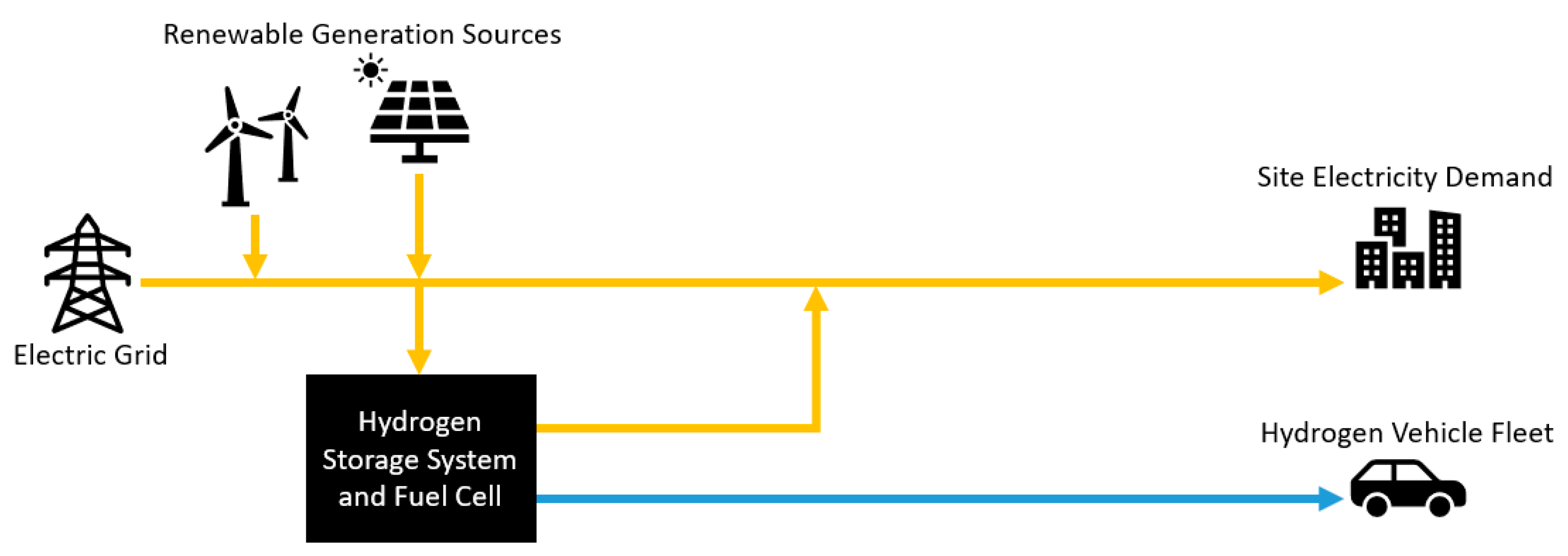
Description of the Test System

The test system under study is an integrated energy system incorporating electricity and hydrogen as energy vectors. It showcases the use of a hydrogen storage system to supply electricity to meet electricity demand of the building site for when electricity import prices are high or when there is not enough renewable energy generation. At the same time, hydrogen is also provided as fuel for a fleet of vehicles. Hydrogen is produced from renewable energy sources (wind and solar PV) at times when production of renewable energy generation exceeds electricity demand. The stored hydrogen can then either be dispatched back to the grid via the fuel cell or used to fuel the fleet of vehicles. The expectation of the system operation is that hydrogen will be produced when either the availability of renewable energy generation is high and/or when the import price of electricity is low. The fuel cell will then enter the operation mode when there is low renewable energy generation and high electricity export price. A simple block diagram depicting the system is shown in Figure 2.
In Figure 2, the yellow lines represent electricity, which can be sourced from either the electric grid, renewable generation sources, the fuel cell, or all at the same time. The blue line represents hydrogen, which is used to fuel the fleet of hydrogen fuelled vehicles.

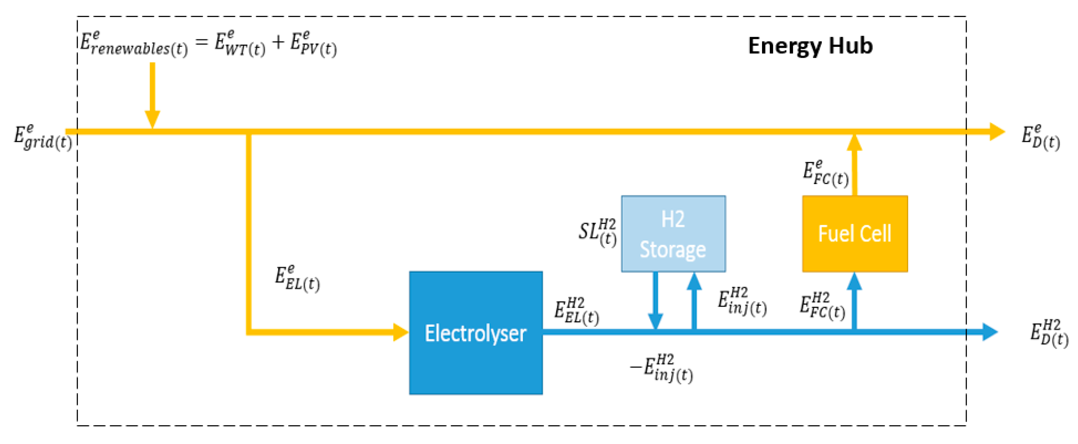
2.2. Problem Formulation

2.2.1. Constrained Optimisation and Mathematical Model

A simplified description of the test system shown in Figure 2 is provided in Figure 3, where
E g r i d ( t ) e : Grid electricity
E D ( t ) e : Electricity demand
E E L ( t ) e : Electrolyser input
E W T ( t ) e : Wind turbine output
E P V ( t ) e : Solar PV output
E F C ( t ) e : Fuel cell output
E D ( t ) H 2 : Hydrogen demand
E E L ( t ) H 2 : Electrolyser output
E F C ( t ) H 2 : Fuel cell input
E i n j   s t o r e ( t ) H 2 : Hydrogen injected/discharged from hydrogen storage system
S L H 2 ( t ) : Storage level
Table 1 summarises the maximum power outputs of the components present in the system under study. These figures are based on the capacities of similar components considered in the Levenmouth Community Energy Project [28,29].
The problem is formulated as a multi-time period optimal dispatch problem, which is solved through constrained optimisation. The objective of the optimisation is to operate the system at the lowest total cost for a certain duration of time. Renewable energy generation profiles, demand (electricity and hydrogen) profiles, and electricity export and import pricing regimes are pre-determined using real data provided by Toshiba Research Europe (from their Levenmouth Community Energy Project) [30].
The power of charging and discharging the hydrogen store is defined as the rate of energy being exchanged in the form of hydrogen gas flowing in and out of the storage tank. The mathematical problem is formulated to quantify the energy exchanged with the hydrogen storage tank at a particular period in a given time horizon. The maximum energy storage capacity of the hydrogen store was determined by multiplying the rated maximum hydrogen weight (specified as 100 kg) and the gravimetric energy density of hydrogen (33.33 kWh/kg), yielding 3333 kWh. As the optimisation is carried out in hourly time steps, the maximum rated power exchange of the hydrogen store is 3333 kW.
The objective function C (total cost) is defined as follows:
t = 1 n C = ( C g r i d ( t ) e × E g r i d ( t ) e )
where, assuming E g r i d e < 0 ,   C g r i d e is the hourly variable electricity export price and, if E g r i d e > 0 , C g r i d e is instead the hourly variable electricity import price.
The objective function given in Equation (3) is set against demand constraints (i.e., the energy balance equations), which are mathematically expressed as follows:
Electricity balance equation:
E d ( t ) e = E g r i d ( t ) e + E W T ( t ) e + E P V ( t ) e E E L ( t ) e + E F C ( t ) e
Hydrogen balance equation:
E D ( t ) H 2 = E E L ( t ) e η E L e / H 2 ± E i n j   s t o r e ( t ) H 2 E F C ( t ) e 1 η F C H 2 / e
where + E i n j   s t o r e ( t ) H 2 indicates that hydrogen storage is being charged, whereas E i n j   s t o r e ( t ) H 2 indicates that hydrogen storage is being discharged.
Equations (4) and (5) are compactly rewritten in matrix form as:
[ E D ( t ) e E W T ( t ) e E P V ( t ) e E D ( t ) H 2 ] = [ 1 1 1 0 η E L e / H 2 0 1 η F C H 2 / e 1 ]   [ E E L ( t ) e E g r i d ( t ) e E F C ( t ) e ± E i n j   s t o r e ( t ) H 2 ]
The efficiencies of the converter devices are as follows [7]:
η E L e / H 2 : Efficiency of electrolyser (85%)
η E L H 2 / e : Efficiency of fuel cell (55%)
The elements in Equation (6) are also subject to the following relationships:
E g r i d ( m i n ) e E g r i d e E g r i d ( m a x ) e
E E L ( m i n ) e E E L e E E L ( m a x ) e
E F C ( m i n ) e E F C e E F C ( m a x ) e
E i n j   s t o r e ( m i n ) H 2 E i n j   s t o r e H 2 E i n j   s t o r e ( m a x ) H 2
S L H 2 ( m i n ) S L H 2 S L H 2 ( m a x )
Equations (7)–(11) represent upper bound and lower bound constraints.
Storage level at the initial time step is chosen as a value lying between the minimum and maximum storage capacities. The corresponding storage levels at the subsequent time steps can be mathematically represented as:
S L H 2 ( t ) = S L H 2 ( t 1 ) + E i n j   s t o r e ( t ) H 2 E s t o r e   o u t ( t ) H 2
Equations (3)–(12) are programmed in MATLAB and the built-in ‘fmincon’ function is used to calculate optimal values for the variables in the energy input matrix at lowest total cost.
Note: It should be highlighted that the energy efficiency of a fuel cell depends on system loading and may influence the optimisation results. The energy efficiency of a fuel cell can be extrapolated using the Willans line approach [31], which shows the relationship between the energy input and the energy output of a converter [32]. However, a fixed efficiency value has been selected for the electrolyser and fuel cell operation in this paper to observe the variation of the energy dispatch within the energy system with respect to the loads and renewable energy generation. A detailed assessment of the electrolyser and fuel cell and their performance depending on the load characteristics, although of significance, falls out of the scope of this work.

2.2.2. Definition of Scenarios

The scenarios studied in this paper are described in Table 2.
The results to be presented in Section 3.1 represent the actual operation of the system. Section 3.2 shows the system operation under the constrained optimisation approach presented in Section 2.2.1, while Section 3.3 summarises the observations made in Section 3.1 and Section 3.2. The aim of the optimisation, with results presented in Section 3.2, is to study the optimal operation of the electrolyser and the fuel cell and the energy management of the hydrogen storage unit. The results of optimal operation are compared with the baseline scenario to elucidate opportunities for an improvement in system operation. The motivation behind the scenarios is that a variation in renewable energy generation profiles should result in different operational behaviours for the electrolyser, hydrogen storage, and fuel cell systems. These scenarios will enable to assess the positive impact of renewable energy generation on the integrated energy system by reducing total operational costs and carbon emissions.
It should be highlighted that electricity and hydrogen demand profiles for the different scenarios are kept the same as in the baseline case. Specifically, the hydrogen demand is derived from the refuelling data of seven vehicles as this information is available from the historical datasets. This is done so that the difference in behaviour of the different technologies within the energy system becomes apparent.
The optimisation problem considers supplying the specified electricity and hydrogen demands as system constraints at minimum site energy cost. Therefore, the optimisation results reflect a dynamic decision-making process on how to manage energy flows within the energy hub for optimal operation considering forecasted renewable generation and grid prices. This is in contrast to the power dispatch method adopted in [6,7], where hydrogen production is directly connected to the availability of excess renewable electricity.
Electricity export and import price profiles are also kept the same for the same reason and reflect typical prices in the UK. Each scenario is run for two weeks within the model at hourly time granularity. A period of one week comprising the optimisation results of the second week has been extracted to avoid start-stop effects of the optimisation in the first week. This was done to prevent bias in the data analysis.
The optimisation results for a week presented in this study are chosen from a two-week simulation period for removing edge effects of the numerical solution. Simulating a week period as opposed to a 24-h period [18], [19] is important as the system employs hydrogen storage and captures variable conditions for energy management. Here observing the differences between weekdays and weekends is of interest as electricity and hydrogen consumption vary as the demands are based on a commercial site with primary demand during weekdays.

3. Results and Discussion

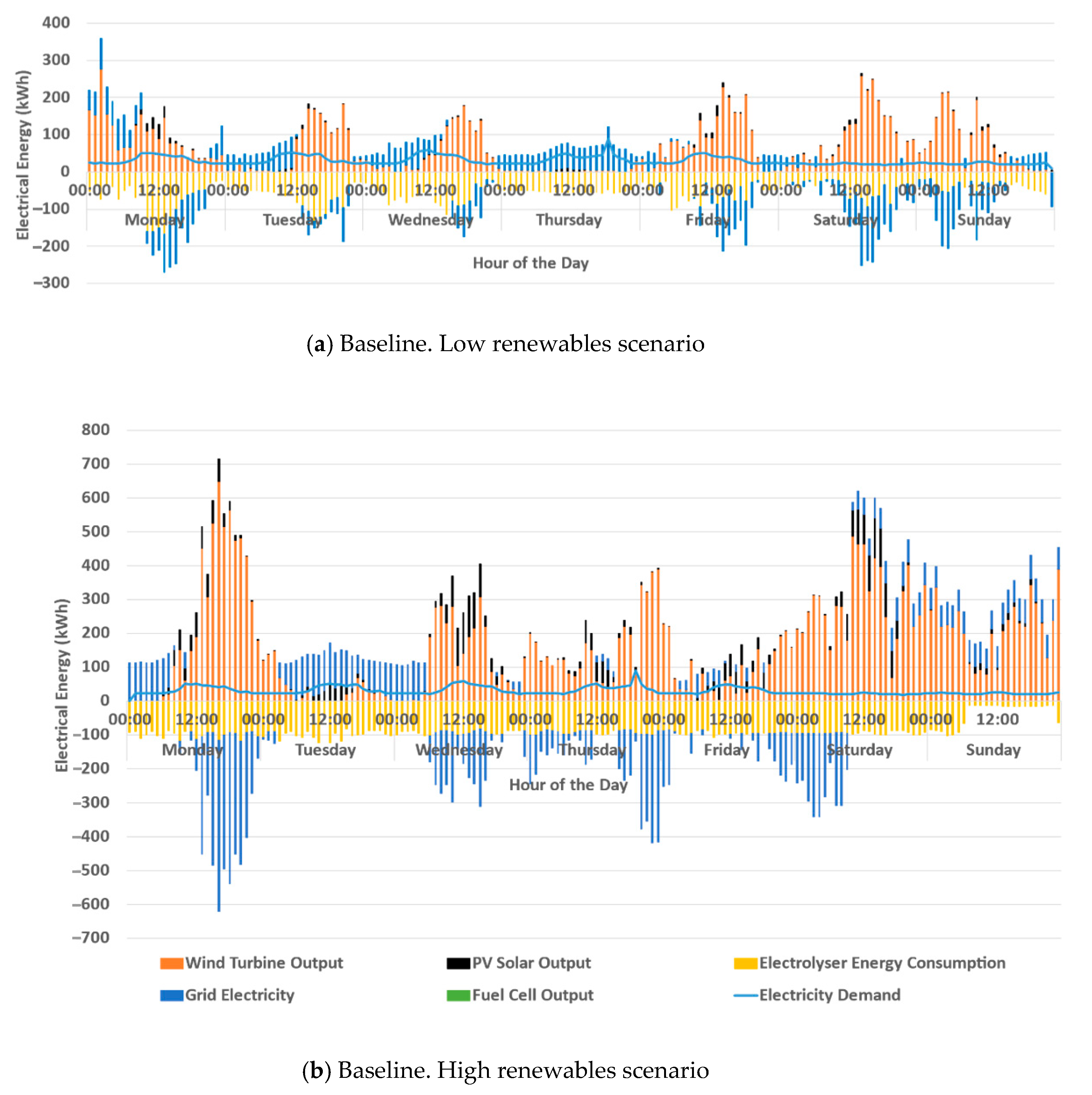
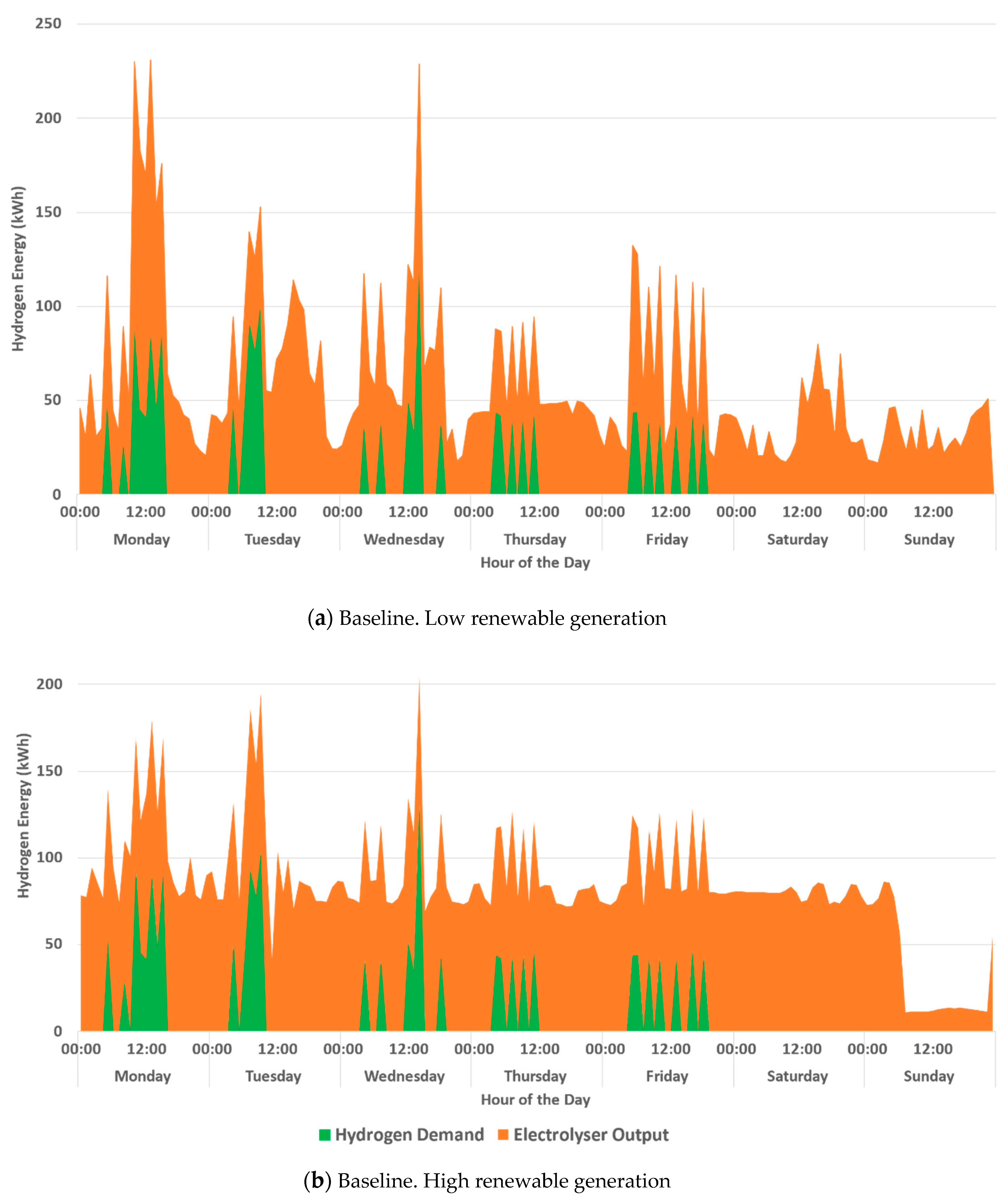
3.1. Baseline Scenarios

As highlighted in Table 2, the baseline scenario is based on real historical data from the Levenmouth Community Energy Project [30]. Figure 4 shows relevant operational data of the electricity system on-site. It should be emphasised that when grid electricity is on the negative Y-axis, this denotes that electricity is being exported back to the grid, whereas when it is on the positive Y-axis, electricity is being imported from the grid.
The historical data indicates that the electrolyser is operated throughout the study period. During certain periods (for instance on Thursday), grid electricity is used to produce hydrogen using the electrolyser and also to meet the on-site electricity demand. Significant quantities of electricity exports are observed particularly during periods with high renewable generation.
Figure 5 shows the operational data on hydrogen production and consumption on-site.
It is relevant to note that on-site hydrogen storage information was not available. Therefore, the analysis of hydrogen storage and its impact is presented and discussed in Section 3.2. Observing the differences in Figure 5a,b, it is evident that the higher and more consistent electrolyser output levels are attributed to the higher renewable energy generation. The electricity and hydrogen demand profile shown in Figure 4a,b, as discussed in Section 2.2.2, will be the same in subsequent studies.

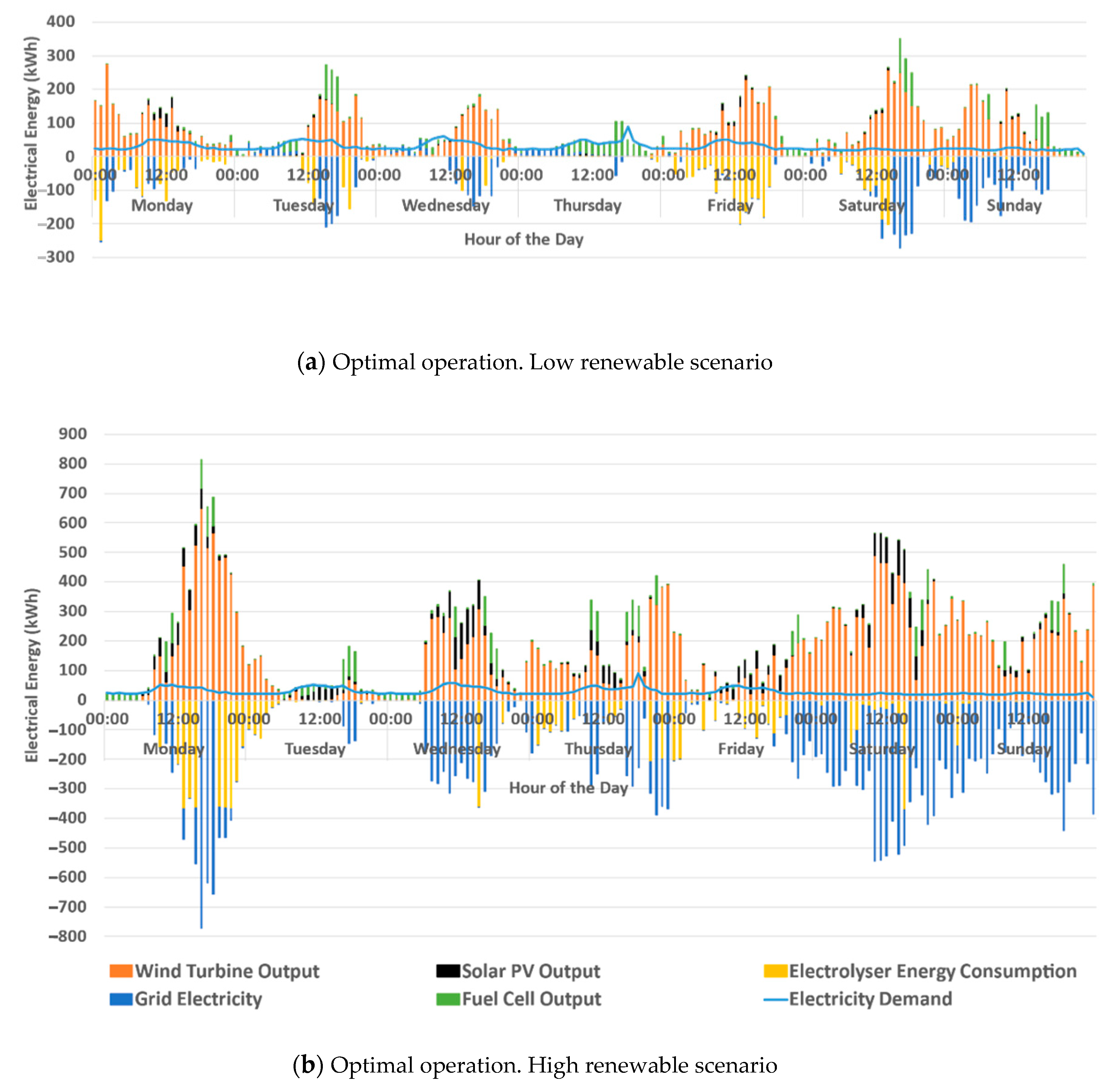
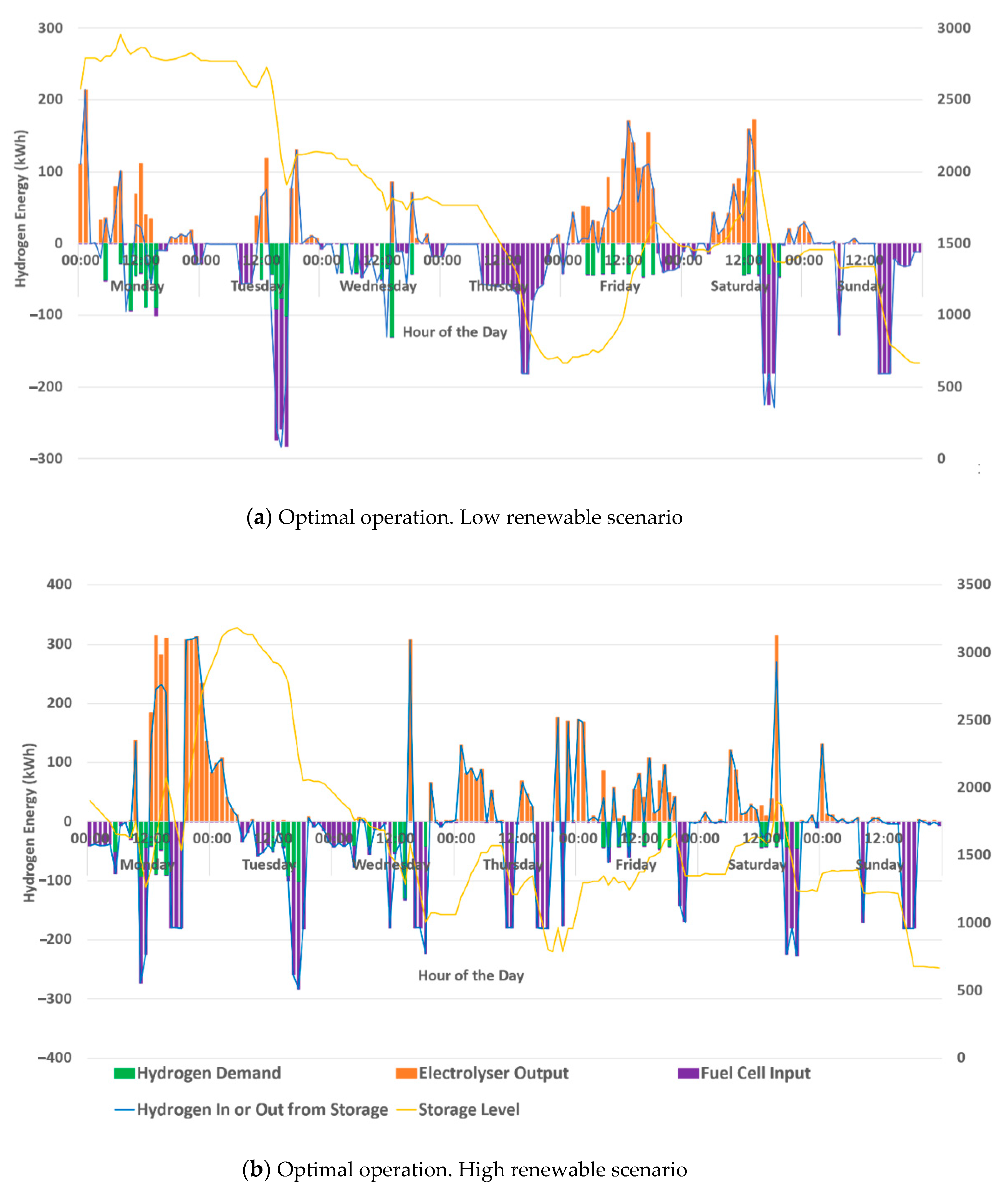
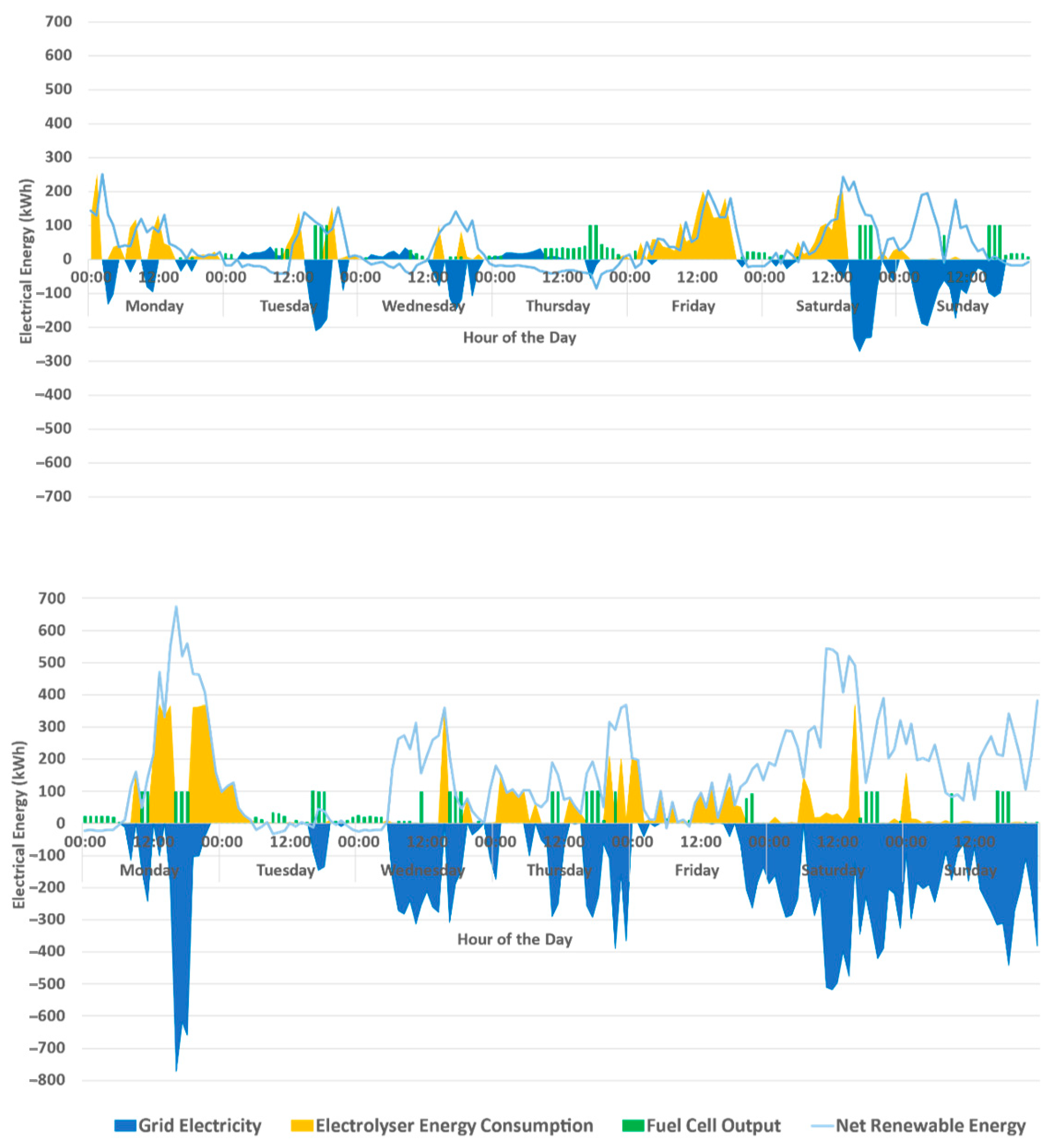
3.2. Optimal Cost Operation for Low and High Renewable Energy Generation Scenarios

These scenarios demonstrate the optimal operation of the test system during a week for both on-site low and high renewable energy generation. Figure 6 shows the optimisation results for the electricity system in these scenarios.
Looking at Figure 6a,b, when the renewable power outputs are high, the electrolyser load increases at the same time (see Figure 6a, Friday, between the hours of 4 am and 6 pm). This is because the system converts excess renewable generation into hydrogen for storage. The fuel cell output follows high electricity import/export prices (16:00–19:00 h) to reduce costs and increase electricity export revenues, and it also compensates for periods with lower renewable energy generation on-site. This is seen on Thursday in Figure 6a, as there is continuous fuel cell utilisation between the hours of 08:00 to 22:00. Having foresight of a low renewable energy generation period triggers the fuel cell to consume stored hydrogen for electricity load balancing purposes so as to avoid importing electricity from the grid.
There is a noticeable difference in the availability of renewable energy generation in Figure 6b compared to Figure 6a. Consequently, higher amounts of electricity are being exported in a high renewable energy generation compared to the low generation scenario, where the highest amount of electricity export is around 250 kWh. In the high renewables scenario, electricity export averages around 500 kWh instead.
Figure 7a,b show the optimisation results for the hydrogen system in the optimal operation scenarios.
As shown in Figure 7a, the hydrogen storage level is at a minimum on Thursday due to utilisation of the fuel cell for electricity generation during the low renewables period. The storage system then re-charges again on Friday when there is significant excess renewable energy generation. In Figure 7b, the behaviour of the hydrogen storage system is consistent with the behaviour shown in Figure 7a, where hydrogen is stored during periods of excess renewable electricity available and is discharged to cover high electricity price periods and periods of low renewable generation. Figure 7b shows the higher availability of renewable energy generation allows for a steadier storage level to be maintained throughout the period of optimisation.
Figure 8 shows the behaviour of the electrolyser and fuel cell and grid electricity against the import and export prices of electricity. In addition, the renewable energy available after serving the site electricity load (net renewable energy) is shown in the graphs as a measure of how much electricity can potentially be used for the electrolyser energy consumption or as electricity export to the grid.
In Figure 8, the electrolyser energy consumption peaks coincide with high levels of net renewable generation. The maximum electrolyser energy consumption at a single instance is observed in the high renewable energy generation scenario. This is expected as there is more net renewable energy available in this scenario. In the low renewable energy generation on Thursday, where there is a period of low renewable energy generation, the system imports electricity between 00:00 to 11:00 h. This period coincides when electricity import prices are low. After 11:00, the system starts using the stored hydrogen in the fuel cell to convert it to electricity. Figure 8 also shows that peaks in import and export prices coincide with one another most of the time. This constrains the site operation to export electricity during these high price periods. The system exports electricity during the peak of electricity export price on each day.

3.3. Summary of Baseline and Optimal Cost Operation Scenarios

Table 3 presents a summary of the results for the different scenarios studied.
From these results, it can be observed that there is more than 2.5 times renewable energy generation available in the high renewables scenario compared to the low renewables scenario. The reason behind this is that electricity and hydrogen demand followed a fixed profile to facilitate the performance comparison of system operation for the different scenarios.
There is a significant reduction in electricity imports in the optimal cost operation compared to the baseline for both low renewables (87% reduction) and high renewables (almost 100%) scenarios. This is due to smart energy management within the site by storing available excess renewable generation using hydrogen storage and its reconversion to electricity using the fuel cell when renewable energy is not available. The significant reduction in electricity imports translate to avoided costs. In addition, electricity imports are reduced, and system revenue is maximised by exporting electricity from excess renewable energy and fuel cell output to make use of high export prices (during 16:00–19:00 hrs). The amount of electricity exported was 4.5 times more in the high renewables scenario compared to the low renewables case.
The electrolyser utilisation was optimised in the optimal cost operation scenarios and showed lower utilisation compared to the baseline cases. It is evident that in the baseline scenarios the electrolyser also uses electricity imported from the grid at a high cost, which is mostly avoided in the optimal cost operation.
The fuel cell plays an important role in balancing the system. It has shown it can help provide electricity to meet electricity demands when renewable generation is not available and, in addition, support revenue generation. The high renewables scenario shows higher utilisation of the fuel cell compared to the low renewables scenario, as expected.
Hydrogen storage is a key enabler for the integrated electricity-hydrogen energy balancing system and has shown that, when designed with the correct capacities, is able to support storage of excess renewable electricity, meet hydrogen demand, and discharge to the fuel cell to convert back to electricity when required. The overall system hinges on the smart management of the hydrogen storage to facilitate energy-cost and carbon savings. Therefore, the ability to better forecast electricity prices and renewable generation ahead of time is an important need for realising this optimised operation.
Note: It should be emphasised that the optimal sizing of equipment and investment analysis of such a system falls outside the scope of the study presented in this paper. However, these aspects should be considered for practical projects as the capital cost of renewable energy technologies and hydrogen technologies are considered a key challenge for commercialisation [33]. However, it is worth noting that the capital cost of electrolysers, fuel cells, and hydrogen storage technologies is decreasing [34,35], which would make such projects economically viable.

4. Conclusions

A method for characterising the operation of an integrated renewable-electricity-hydrogen energy system suitable for decarbonising energy and transport demands of a commercial site has been demonstrated in this paper. The method is suitable for studying the techno-economic and environmental behaviour of energy systems of specific sites to characterise operation with new technologies for cost and carbon minimisation. Real operation data available from an actual project, the Levenmouth Community Energy Project, is demonstrated to gain valuable insights on the electricity demand and the energy demands of a hydrogen vehicle fleet and the potential for renewable energy generation. Data and information from real electricity-hydrogen energy systems are rare in published literature, so this paper also contributes an interesting real case study and actual operational data for the wider research community.
The results show that by integration of renewable technologies, electrolyser, hydrogen storage, and fuel cell technologies, the site energy system can gain significant operational cost and carbon savings particularly during periods of high renewable generation. The results indicate the need for operation scheduling and advanced control of the integrated system considering forecasts of renewable generation and electricity prices to ensure that low periods of renewable generation and high electricity price periods are managed effectively. The results show that optimum operation involves modulating the electrolyser to follow on-site renewable generation and modulating the fuel cell output to reduce electricity imports and generate revenue during periods of high prices. Hydrogen storage is a central part of the overall electricity and hydrogen system integration and to the ability to time-shift renewable energy to periods of electricity and hydrogen demands. It is important to note that actual operation savings may deviate from the results shown as this study assumes perfect foresight of system conditions.
The methodology presented is transferrable and scalable to sites of similar structure and the general findings will be applicable. The optimisation results shown are applicable to the UK conditions where time-varying import and export prices are utilised. The grid prices are a determining external factor for site operation and should reflect the local conditions when applied.

Author Contributions

O.U. conducted the research reported in this paper and led the writing exercise, worked on the optimisation model, and the literature review. M.A. and C.E.U.-L. contributed to the writing of the paper. They act as research supervisors of the first author (O.U.). All authors have read and agreed to the published version of the manuscript.

Funding

The research presented in this paper was supported in part by FLEXIS—a project part-funded by the European Regional Development Fund (ERDF) through the Welsh Government.

Data Availability Statement

The data presented in this study may be available on request from the corresponding author. The data are not publicly available as they belong to a 3rd party (Bristol Toshiba Research and Innovation Laboratory).

Acknowledgments

The authors acknowledge the support from Bristol Toshiba Research and Innovation Laboratory who made available the data for this study. The test system data and system configuration related information used in this paper have been collected as part of the Levenmouth Community Energy Project (LCEP), which has received funding from the Scottish government and industrial participants. The project partners are Bright Green Hydrogen Ltd., Fife Council, Leven Valley Development Trust (LVDT), Fife College, Green Business Fife (GBF), Scottish Hydrogen and Fuel Cell Association (SHFCA), Toshiba, BOC, and Community Energy Scotland (CES).

Conflicts of Interest

The authors declare no conflict of interest.

References

  1. The Royal Society. Options for Producing Low-Carbon Hydrogen at Scale; The Royal Society: London, UK, 2018. [Google Scholar]
  2. Kakoulaki, G.; Kougias, I.; Taylor, N.; Dolci, F.; Moya, J.; Jäger-Waldau, A. Green hydrogen in Europe—A regional assessment: Substituting existing production with electrolysis powered by renewables. Energy Convers. Manag. 2020, 228, 113649. [Google Scholar] [CrossRef]
  3. Moore, J.; Shabani, B. A Critical Study of Stationary Energy Storage Policies in Australia in an International Context: The Role of Hydrogen and Battery Technologies. Energies 2016, 9, 674. [Google Scholar] [CrossRef]
  4. Xiang, Y.; Cai, H.; Liu, J.; Zhang, X. Techno-economic design of energy systems for airport electrification: A hydrogen-solar-storage integrated microgrid solution. Appl. Energy 2021, 283, 116374. [Google Scholar] [CrossRef]
  5. Cheng, Y.; Liu, M.; Chen, H.; Yang, Z. Optimization of multi-carrier energy system based on new operation mechanism modelling of power-to-gas integrated with CO2-based electrothermal energy storage. Energy 2021, 216, 119269. [Google Scholar] [CrossRef]
  6. Ding, X.; Sun, W.; Harrison, G.P.; Lv, X.; Weng, Y. Multi-objective optimization for an integrated renewable, power-to-gas and solid oxide fuel cell/gas turbine hybrid system in microgrid. Energy 2020, 213, 118804. [Google Scholar] [CrossRef]
  7. Hajimiragha, A.; Canizares, C.; Fowler, M.; Geidl, M.; Andersson, G. Optimal Energy Flow of integrated energy systems with hydrogen economy considerations. In Proceedings of the 2007 iREP Symposium-Bulk Power System Dynamics and Control-VII. Revitalizing Operational Reliability, Charleston, SC, USA, 19–24 August 2007; pp. 1–11. [Google Scholar]
  8. Kholardi, F.; Assili, M.; Lasemi, M.A.; Hajizadeh, A. Optimal Management of Energy Hub with Considering Hydrogen Network. In Proceedings of the 2018 International Conference on Smart Energy Systems and Technologies (SEST), Seville, Spain, 10–12 September 2018; IEEE: Piscataway, NJ, USA, 2018; pp. 1–6. [Google Scholar]
  9. Farahani, S.S.; Bleeker, C.; van Wijk, A.; Lukszo, Z. Hydrogen-based integrated energy and mobility system for a real-life office environment. Appl. Energy 2020, 264, 114695. [Google Scholar] [CrossRef]
  10. Mansour-Saatloo, A.; Agabalaye-Rahvar, M.; Mirzaei, M.A.; Mohammadi-Ivatloo, B.; Abapour, M.; Zare, K. Robust scheduling of hydrogen based smart micro energy hub with integrated demand response. J. Clean. Prod. 2020, 267, 122041. [Google Scholar] [CrossRef]
  11. Mansour-Saatloo, A.; Mirzaei, M.A.; Mohammadi-Ivatloo, B.; Zare, K. A Risk-Averse Hybrid Approach for Optimal Participation of Power-to-Hydrogen Technology-Based Multi-Energy Microgrid in Multi-Energy Markets. Sustain. Cities Soc. 2020, 63, 102421. [Google Scholar] [CrossRef]
  12. Akhoundzadeh, M.H.; Raahemifar, K.; Panchal, S.; Samadani, E.; Haghi, E.; Fraser, R.; Fowler, M. A Conceptualized Hydrail Powertrain: A Case Study of the Union Pearson Express Route. World Electr. Veh. J. 2019, 10, 32. [Google Scholar] [CrossRef] [Green Version]
  13. Zhao, G.; Nielsen, E.R. Social Impact Assessment of BIG HIT: A Report into the Societal Impact of the Project; Department of Energy Conversion and Storage, Technical University of Denmark: Kongens Lyngby, Denmark, 2018. [Google Scholar]
  14. Arat, H.T.; Sürer, M.G. State of art of hydrogen usage as a fuel on aviation. Eur. Mech. Sci. 2017, 2, 20–30. [Google Scholar] [CrossRef]
  15. Geidl, M. Integrated Modeling and Optimization of Multi-Carrier Energy Systems. Ph.D. Thesis, ETH Zurich, Zurich, Switzerland, 2007. [Google Scholar] [CrossRef]
  16. Zhang, W.; Han, N.; Sun, W.; Li, H.; Tan, Y.; Yan, Z.; Dong, X. Optimal operation of wind-solar-hydrogen storage system based on energy hub. In Proceedings of the 2017 IEEE Conference on Energy Internet and Energy System Integration (EI2), Beijing, China, 26–28 November 2017; pp. 1–5. [Google Scholar]
  17. Alrafea, K.; Fowler, M.; Elkamel, A.; Hajimiragha, A. Integration of renewable energy sources into combined cycle power plants through electrolysis generated hydrogen in a new designed energy hub. Int. J. Hydrog. Energy 2016, 41, 16718–16728. [Google Scholar] [CrossRef]
  18. Daraei, M.; Campana, P.E.; Thorin, E. Power-to-hydrogen storage integrated with rooftop photovoltaic systems and combined heat and power plants. Appl. Energy 2020, 276, 115499. [Google Scholar] [CrossRef]
  19. Mendes, P.R.D.C.; Normey-Rico, J.E.; Alba, C.B. Economic Energy Management of a Microgrid Including Electric Vehicles. In Proceedings of the 2015 IEEE PES Innovative Smart Grid Technologies Latin America (ISGT LATAM), Montevideo, Uruguay, 5–7 October 2015; pp. 869–874. [Google Scholar]
  20. Proietto, R.; Arnone, D.; Bertoncini, M.; Rossi, A.; La Cascia, D.; Miceli, R.; Sanseverino, E.R.; Zizzo, G. Mixed heuristic-non linear optimization of energy management for hydrogen storage-based multi carrier hubs. In Proceedings of the 2014 IEEE International Energy Conference (ENERGYCON), Dubrovnik, Croatia, 13–16 May 2014; pp. 1019–1026. [Google Scholar]
  21. Gökçek, M.; Kale, C. Optimal design of a Hydrogen Refuelling Station (HRFS) powered by Hybrid Power System. Energy Convers. Manag. 2018, 161, 215–224. [Google Scholar] [CrossRef]
  22. Geng, S.; Vrakopoulou, M.; Hiskens, I.A. Optimal Capacity Design and Operation of Energy Hub Systems. Proc. IEEE 2020, 108, 1475–1495. [Google Scholar] [CrossRef]
  23. Chicco, G.; Riaz, S.; Mazza, A.; Mancarella, P. Flexibility from Distributed Multienergy Systems. Proc. IEEE 2020, 108, 1496–1517. [Google Scholar] [CrossRef]
  24. Nosratabadi, S.M.; Jahandide, M.; Nejad, R.K. Simultaneous planning of energy carriers by employing efficient storages within main and auxiliary energy hubs via a comprehensive MILP modeling in distribution network. J. Energy Storag. 2020, 30, 101585. [Google Scholar] [CrossRef]
  25. Vian, A.; Bignucolo, F.; De Carli, M. Modelling and Optimization Approach of Residential Energy Hub: The GHOTEM Project. In Proceedings of the 2019 1st International Conference on Energy Transition in the Mediterranean Area (SyNERGY MED), Cagliary, Italy, 28–30 May 2019; pp. 1–6. [Google Scholar]
  26. Geidl, M.; Andersson, G. Optimal Power Dispatch and Conversion Systems with Multiple Energy Carriers. In Proceedings of the Power Systems Computation Conference, Liege, Belgium, 22–26 August 2005. [Google Scholar]
  27. Geidl, M.; Koeppel, G.; Favre-Perrod, P.; Klockl, B.; Andersson, G.; Frohlich, K. Energy hubs for the future. IEEE Power Energy Mag. 2007, 5, 24–30. [Google Scholar] [CrossRef]
  28. Farnham, T. Using Telemetry Data for Optimising Dual Fuel Hydrogen/Diesel Vehicle Fleets. In Proceedings of the 2018 International Conference on Smart Energy Systems and Technologies (SEST), Seville, Spain, 10–12 September 2018; pp. 1–6. [Google Scholar]
  29. Levenmouth Community Energy Project. Fife, n.d. Available online: https://www.brightgreenhydrogen.org.uk/levenmouth-community-energy-project/ (accessed on 19 January 2021).
  30. Pzip—Data Repository Site. Available online: ftp://ldr.toshiba-trel.com/1073 (accessed on 19 January 2021).
  31. Rizzoni, G.; Guzzella, L.; Baumann, B. Unified modeling of hybrid electric vehicle drivetrains. Asme Trans. Mechatron. 1999, 4, 246–257. [Google Scholar] [CrossRef]
  32. Pachernegg, S.J. A Closer Look at the Willans-Line. Sae Tech. Pap. Ser. 1969. [Google Scholar] [CrossRef]
  33. Ball, M.; Weeda, M. The Hydrogen Economy—Vision or Reality? In Compendium of Hydrogen Energy; Energy Series; Ball, M., Basile, A., Veziroğlu, T.N., Eds.; Woodhead Publishing: Sawston, UK, 2016; pp. 237–266. [Google Scholar]
  34. Cloete, S.; Ruhnau, O.; Hirth, L. On capital utilization in the hydrogen economy: The quest to minimize idle capacity in renewables-rich energy systems. Int. J. Hydrog. Energy 2021, 46, 169–188. [Google Scholar] [CrossRef]
  35. Khzouz, M.; Gkanas, E.I.; Shao, J.; Sher, F.; Beherskyi, D.; El-Kharouf, A.; Al Qubeissi, M. Life Cycle Costing Analysis: Tools and Applications for Determining Hydrogen Production Cost for Fuel Cell Vehicle Technology. Energies 2020, 13, 3783. [Google Scholar] [CrossRef]
Figure 1. Example of an energy hub [27].
Sustainability 13 03525 g001
Figure 2. Simplified block diagram of the system under study.
Sustainability 13 03525 g002
Figure 3. Energy hub representation of the integrated energy system under study.
Sustainability 13 03525 g003
Figure 4. Electricity system data for baseline scenarios: (a) low renewables; (b) high renewables.
Sustainability 13 03525 g004
Figure 5. Hydrogen system data for baseline scenarios: (a) low renewables; (b) high renewables.
Sustainability 13 03525 g005
Figure 6. Electricity system data for optimal operation: (a) low renewables; (b) high renewables.
Sustainability 13 03525 g006
Figure 7. Hydrogen system data for optimal operation: (a) low renewables; (b) high renewables (hydrogen storage level on right-hand side Y-axis).
Sustainability 13 03525 g007
Figure 8. Fuel cell and electrolyser operation against electricity import and export prices.
Sustainability 13 03525 g008aSustainability 13 03525 g008b
Table 1. Maximum power output capacities of system components.
System ComponentRated Maximum Power Capacity (kW)
Wind Turbine750
Solar PV200
Electrolyser370
Fuel Cell100
Hydrogen Storage3333
Table 2. Description of scenarios.
ScenarioDescription
Baseline performance for one week operation of a real system with both low and high renewable energy generation • Actual operation data from the Levenmouth Community Energy Project for a similar system configuration is used [29]. The data was made available by Toshiba Bristol Research and Innovation Labs [30]. This is used to establish the electricity and hydrogen demands and the renewable generation profiles for subsequent scenarios.
• On-site hydrogen storage data is not available.
• Fuel cell is not in operation.
One week cost optimal operation of the test system with low renewable energy generation.• Electricity demand accounts for 42% of the on-site renewable energy generation.
• Electricity and hydrogen demand as in base scenario.
• Electrolyser, hydrogen storage and fuel cell operated for cost minimisation.
One week cost optimal operation of the test system with high renewable energy generation. • Electricity demand accounts for 16% of the on-site renewable energy generation.
• Electricity and hydrogen demand as in base scenario.
• Electrolyser, hydrogen storage and fuel cell operated for cost minimisation.
Table 3. Summary of baseline and optimisation results.
Low RenewablesHigh Renewables
BaselineOptimal OperationBaselineOptimal Operation
Site Electricity Demand (kWh)5228.375228.375051.715051.71
Site Hydrogen Demand (kWh)1722.411722.411722.411722.41
Renewable Energy Available (kWh)11,981.6611,981.6631,734.6031,734.60
Electrolyser energy consumption (kWh)9526.214280.0814,629.357437.03
Fuel Cell energy output (kWh)-2049.66-3231.74
Stored Hydrogen (kWh)-2846.2-5643.5
Discharged Hydrogen (kWh)-4657.2-6920.3
Total Electricity Imports (kWh)4081.20515.8263720.03
Total Electricity Exports (kWh)5061.205066.2010,71822,858
Total cost of operation (£)-−239.8-−1118
Publisher’s Note: MDPI stays neutral with regard to jurisdictional claims in published maps and institutional affiliations.

