
Natural Clay Minerals as a Starting Material for Matrices for the Immobilization of Radioactive Waste from Pyrochemical Processing of SNF

 ,
,
Abstract
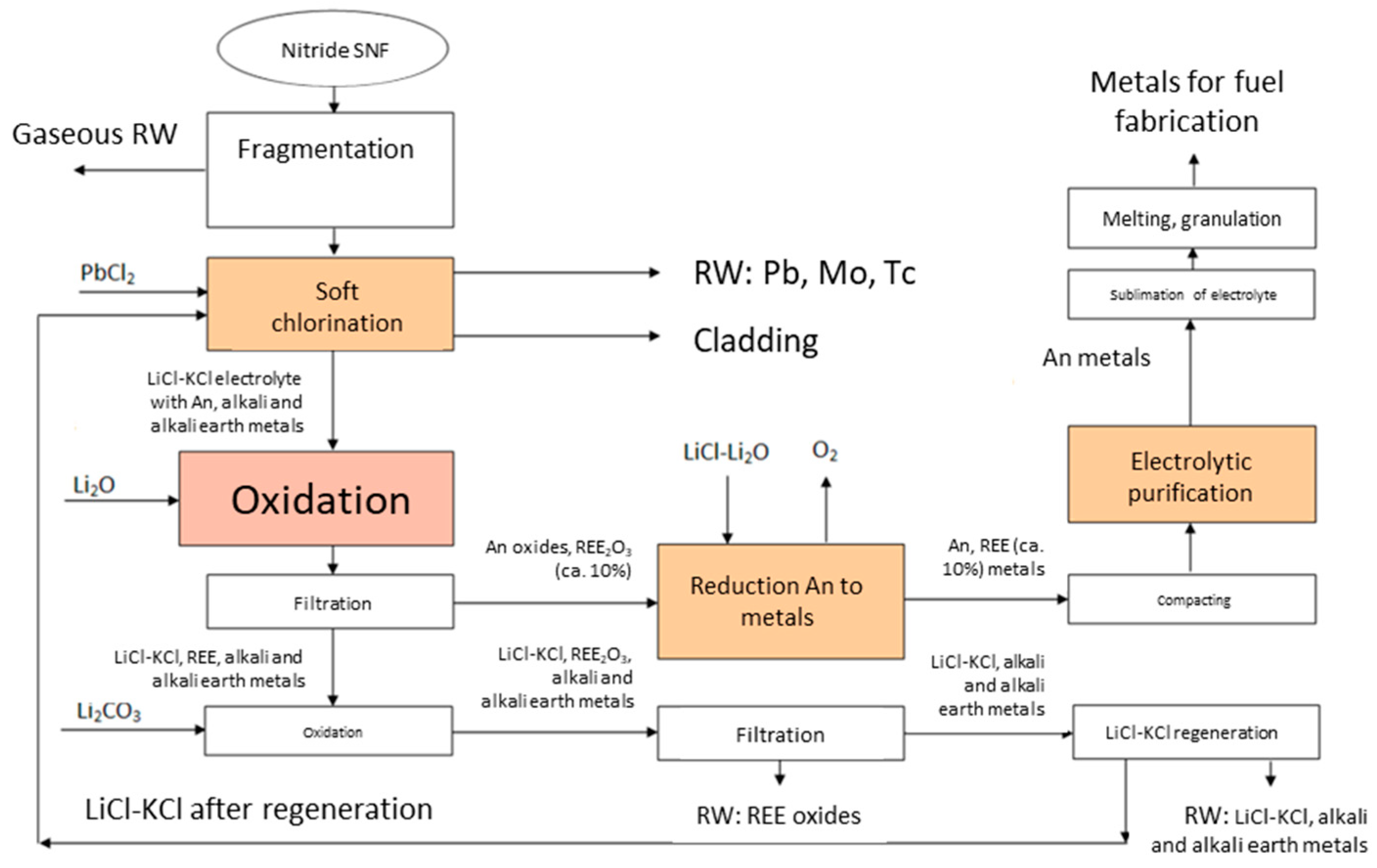
:1. Introduction
2. Materials and Methods
3. Results and Discussion
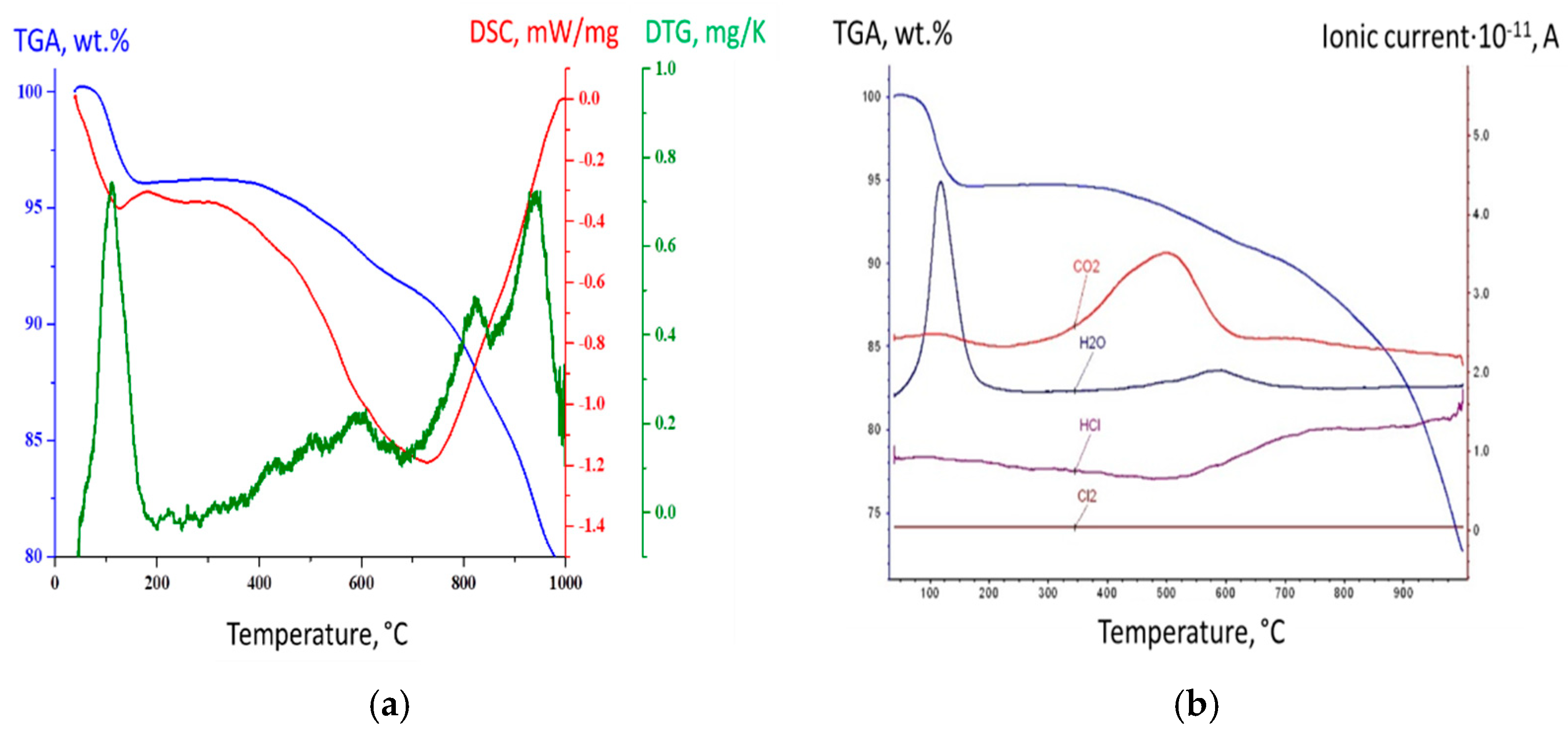
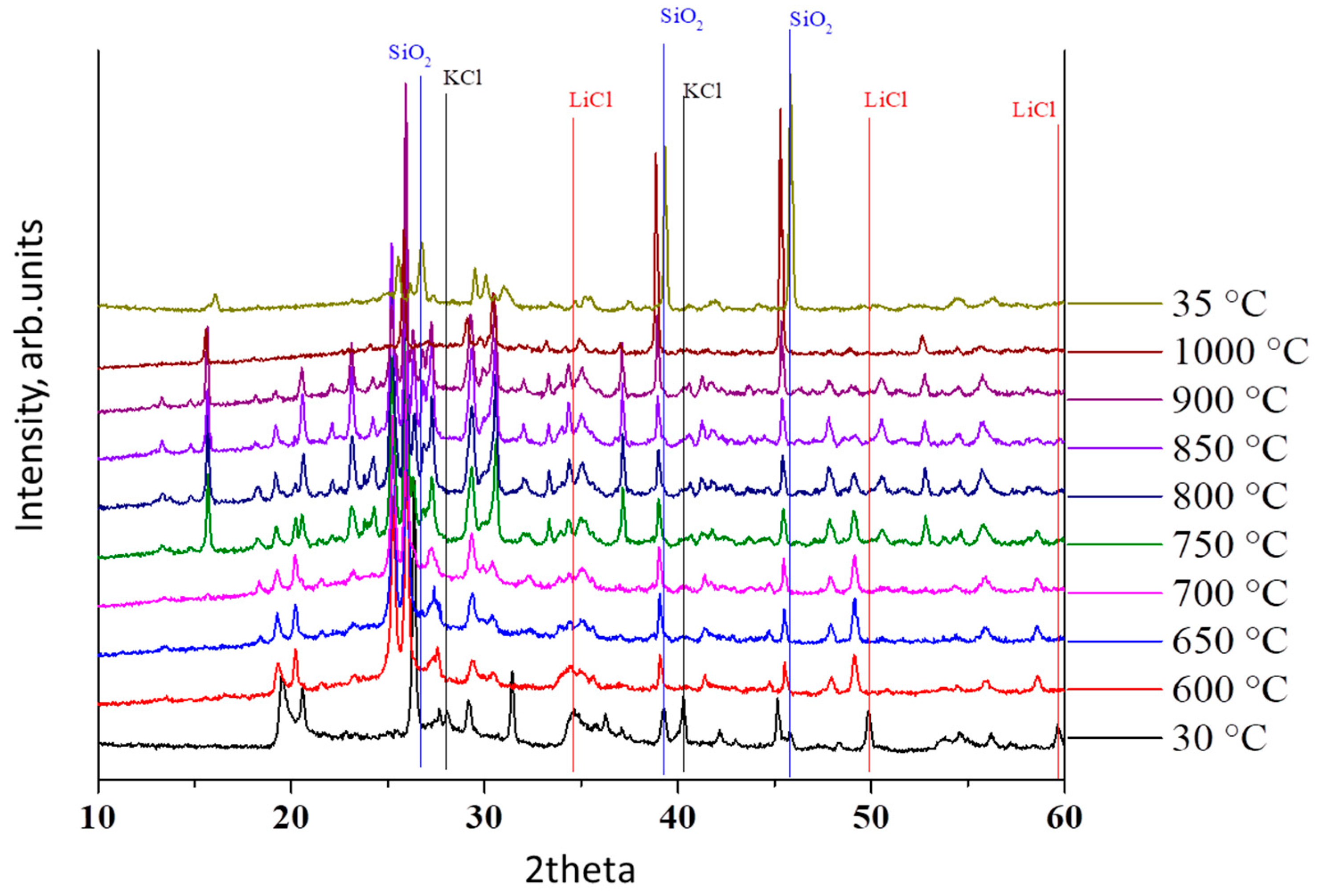
3.1. Thermal Analysis
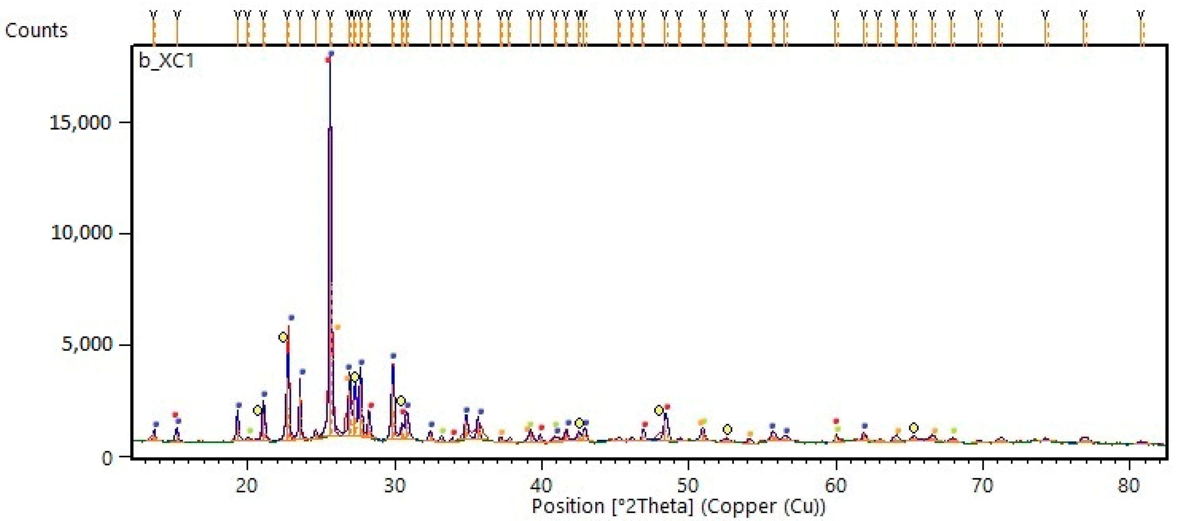
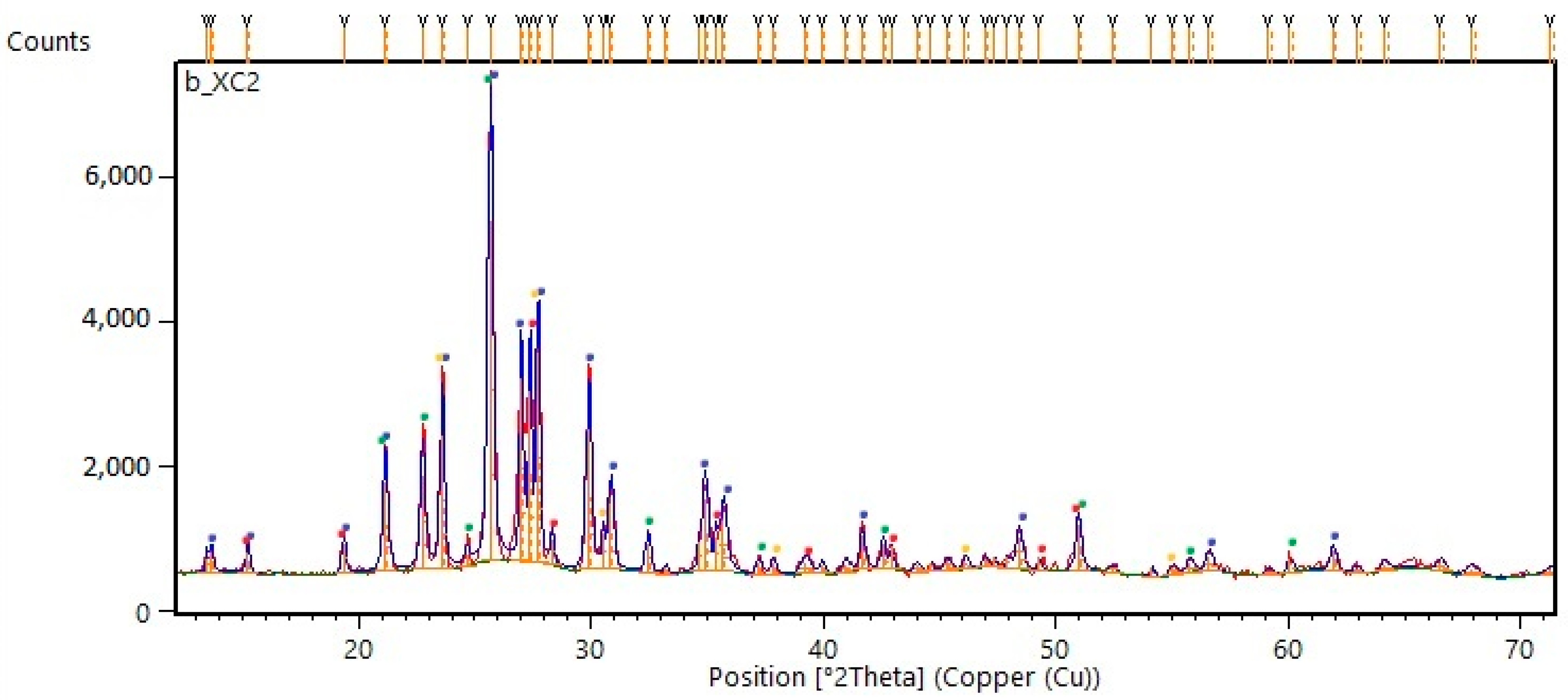
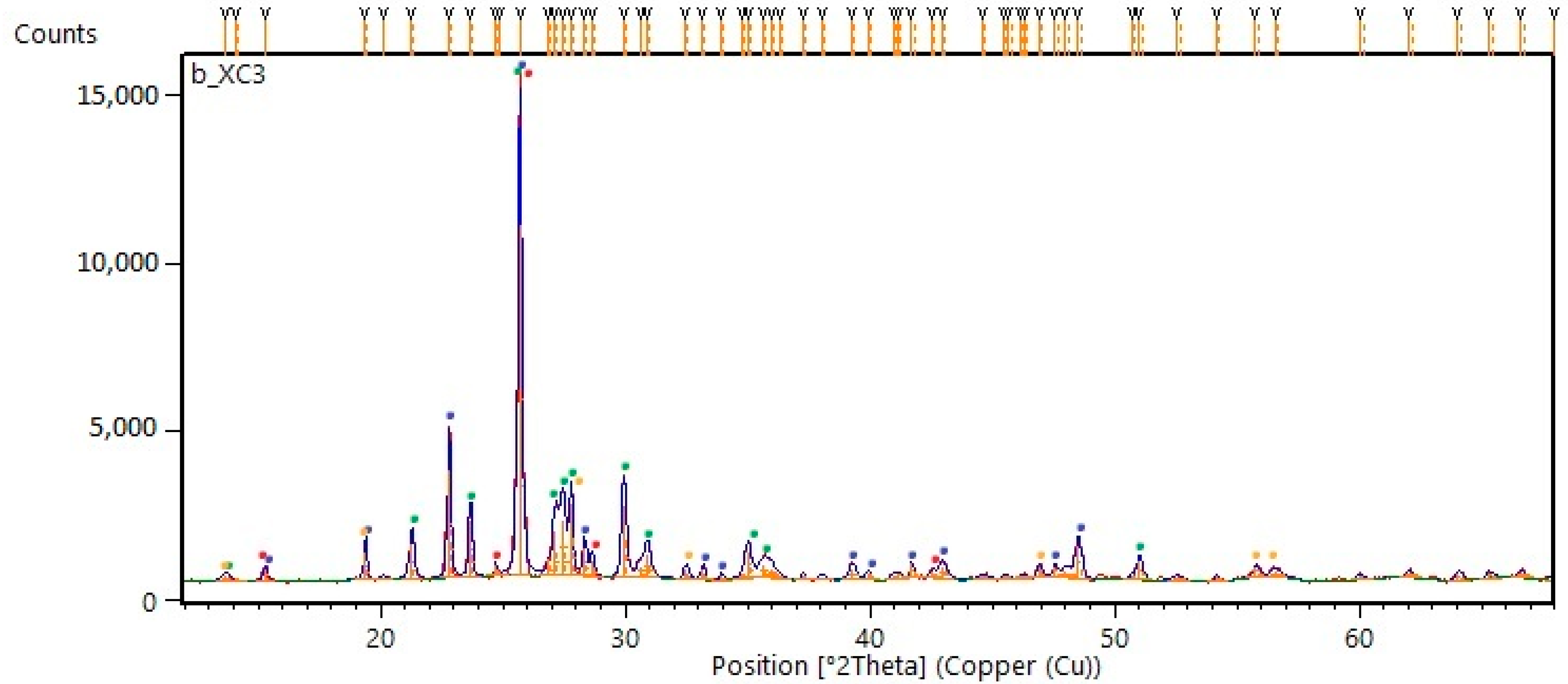
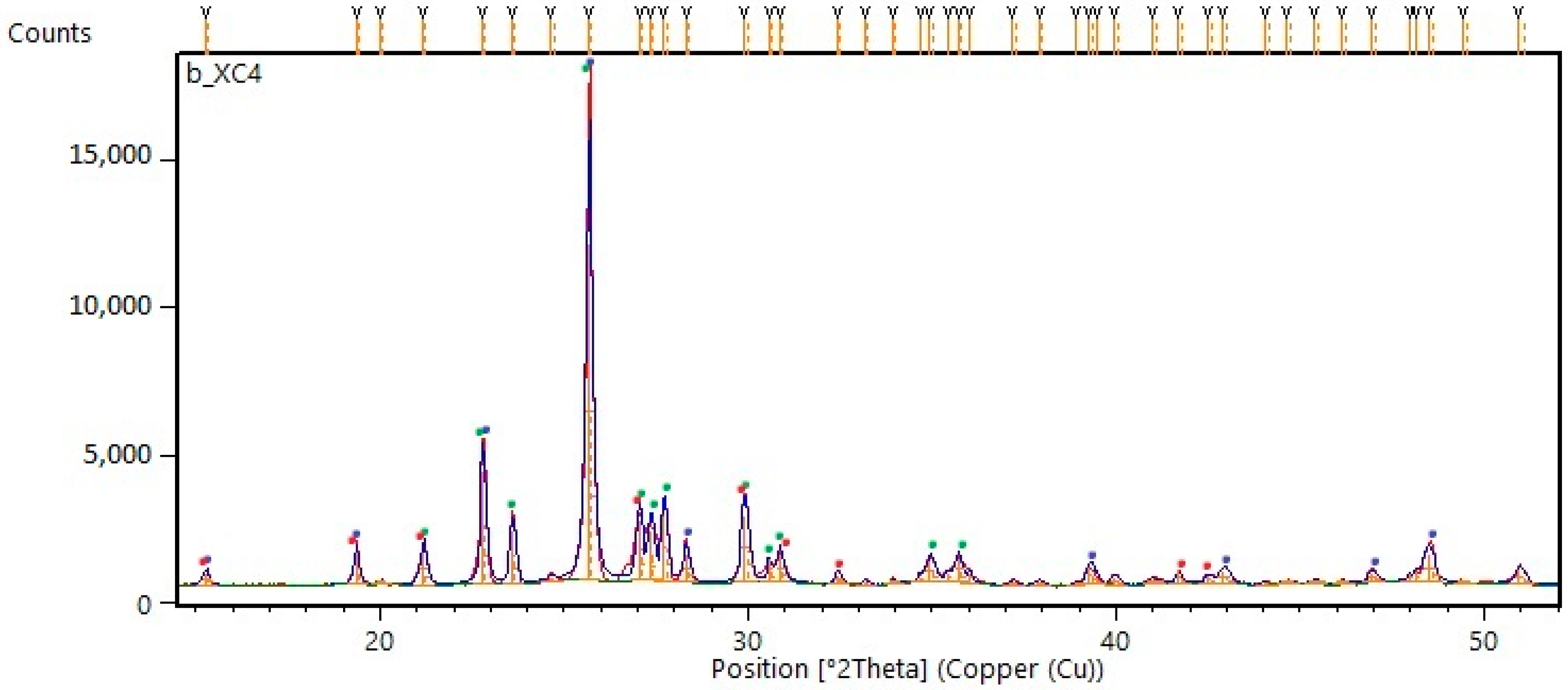
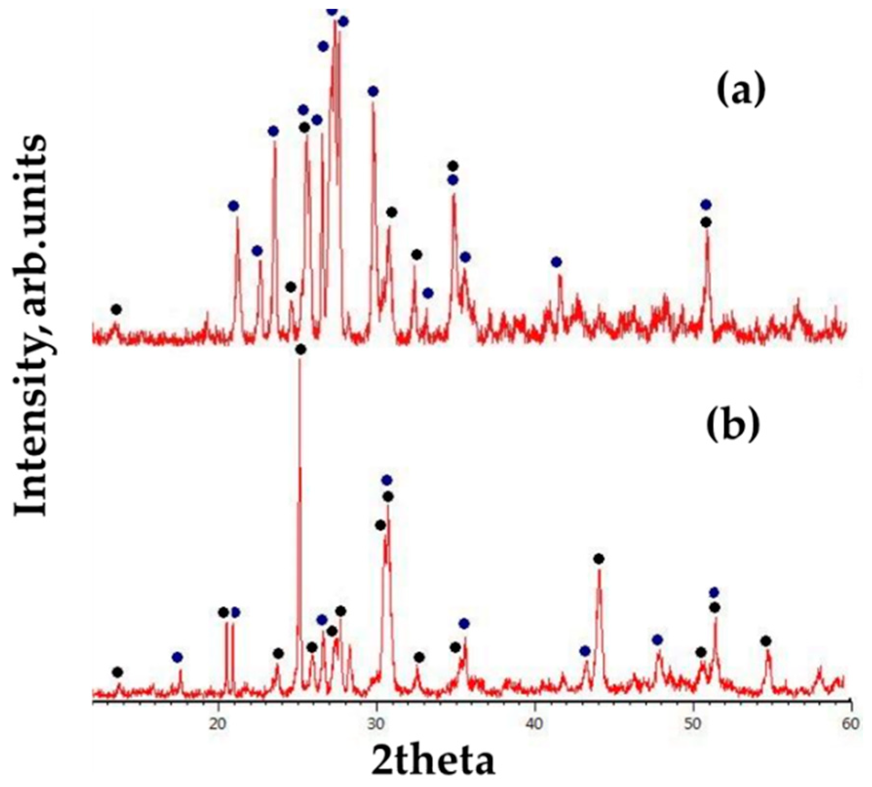
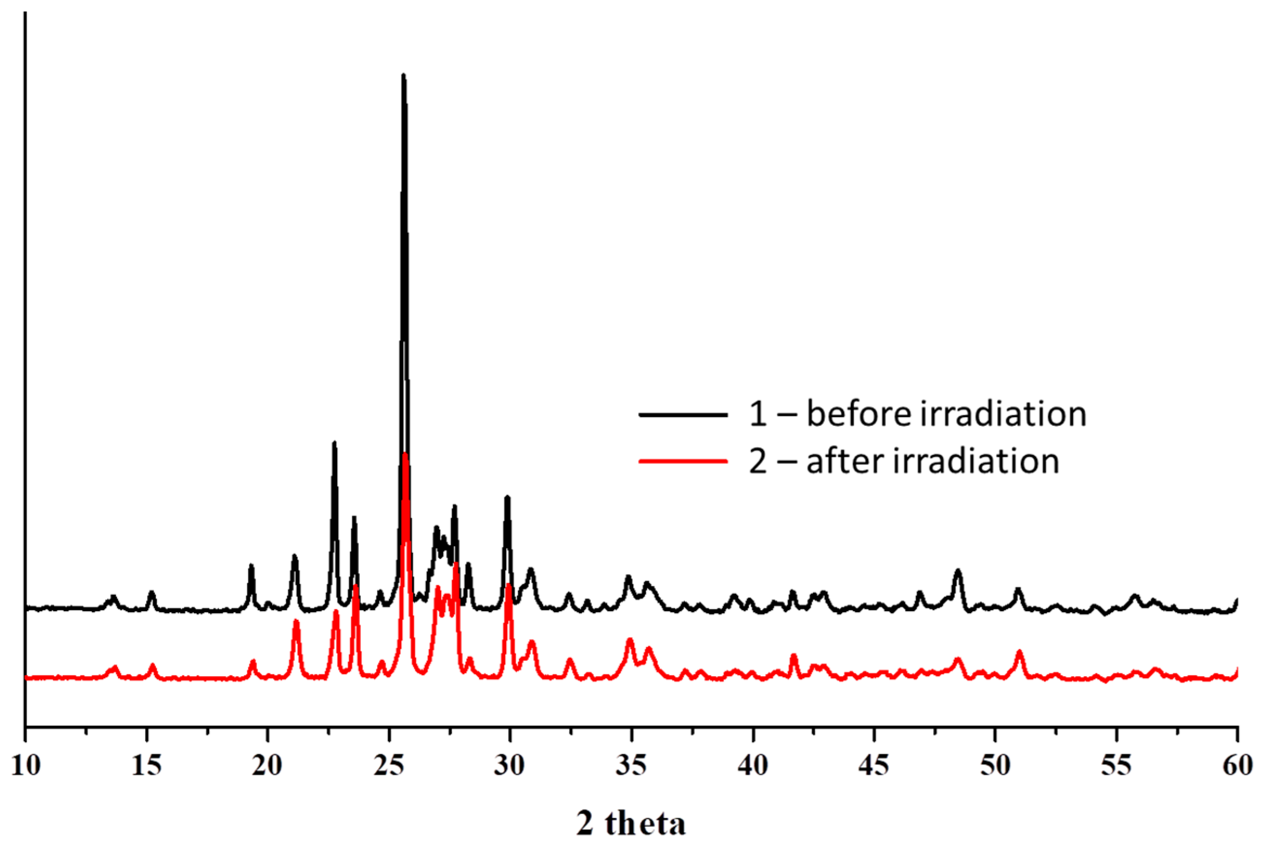
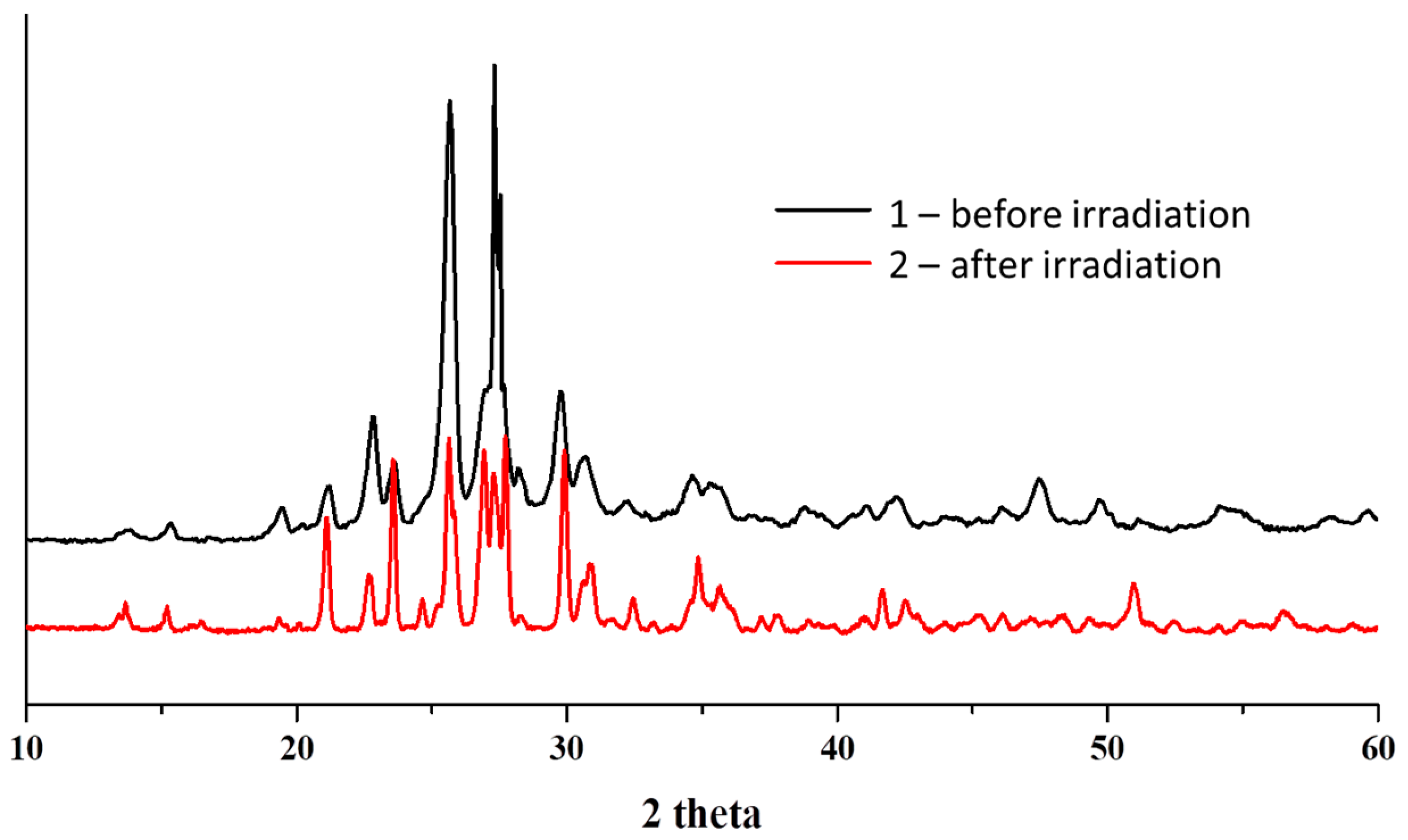
3.2. X-ray Diffraction Analysis
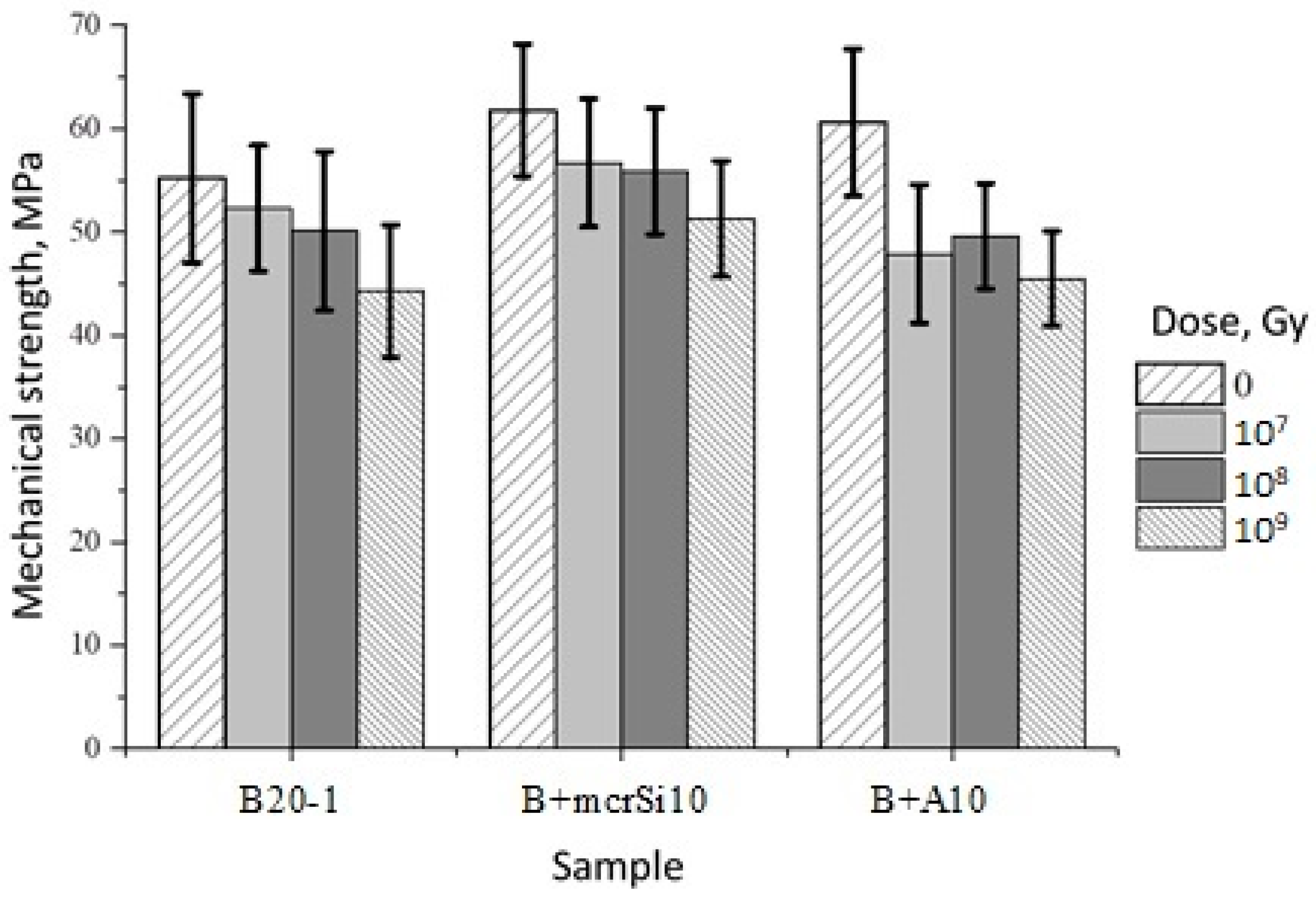
3.3. Mechanical Compressive Strength
3.4. Hydrolytic Stability
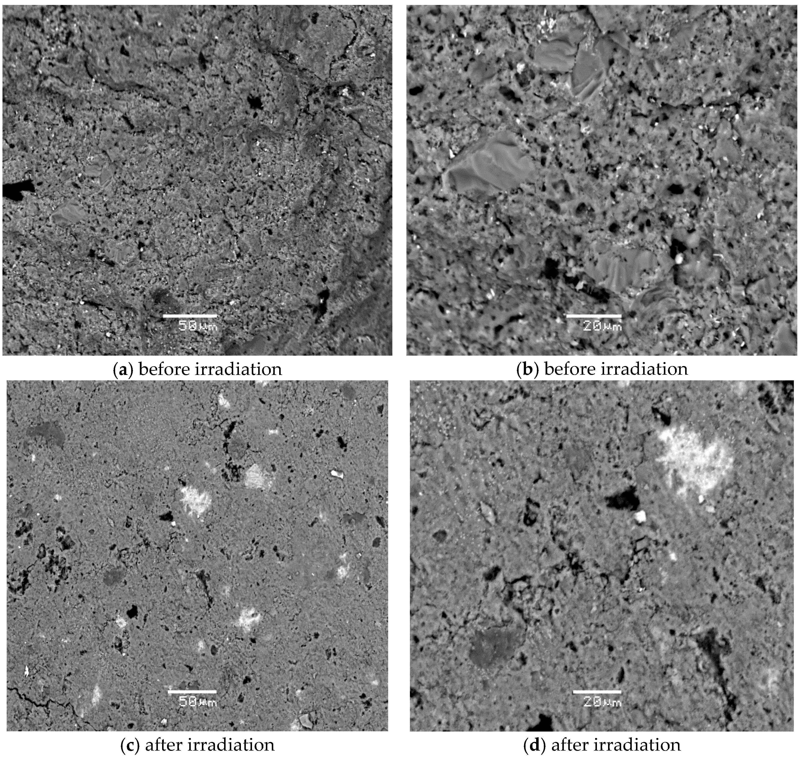
3.5. Effect of Irradiation on the Characteristics of the Samples
4. Conclusions
- Specific mechanical characteristics (compressive strength ≥10 MPa);
- Radiation resistance (without changes in mechanical strength and structure at an absorbed dose of up to 109 Gy);
- Leaching rate (for all components ≤10−6 g/(cm2·day)).
Author Contributions
Funding
Data Availability Statement
Conflicts of Interest
References
- Jantzen, C.M. Development of glass matrices for high level radioactive wastes. In Handbook of Advanced Radioactive Waste Conditioning Technologies; Ojovan, M.I., Ed.; Woodhead Publishing Limited: Cambridge, UK, 2011; pp. 230–292. [Google Scholar]
- Mochalov, Y.S. Report on the Project Direction “Proryv”: “Place and Advantages of the Project in the Development of the World Energy System”, 7–8, June 2016. Available online: http://proryv2020.ru/en/opinion/(accessed on 13 September 2021).
- Sobolev, I.A.; Ozhovan, M.I.; Shcherbatova, T.D.; Batyukhnova, O.G. Glasses for Radioactive Waste; Energoatomizdat: Moscow, Russia, 1999. [Google Scholar]
- Lee, K.R.; Riley, B.J.; Park, H.S.; Choi, J.H.; Han, S.Y.; Hur, J.M.; Peterson, J.A.; Zhu, Z.; Schreiber, D.K.; Kruska, K.; et al. Investigation of physical and chemical properties for upgraded SAP (SiO2Al2O3P2O5) waste form to immobilize radioactive waste salt. J. Nucl. Mat. 2019, 515, 382–391. [Google Scholar] [CrossRef]
- Lavrinovich, Y.G.; Kormilitsyn, M.V.; Konovalov, V.I.; Tselishchev, I.V.; Tomilin, S.V.; Chistyakov, V.M. Vitrification of chloride wastes in the pyroelectrochemical method of reprocessing irradiated nuclear fuel. At. Energy 2003, 95, 781–785. [Google Scholar] [CrossRef]
- Leturcq, G.; Grandjean, A.; Rigaud, D.; Perouty, P.; Charlot, A.M. Immobilization of fission products arising from pyrometallurgical reprocessing in chloride media. J. Nucl. Mat. 2005, 347, 1–11. [Google Scholar] [CrossRef]
- Lutze, W.; Ewing, R.C. Radioactive Waste Forms for the Future; Elsevier Science Pub. Co. Inc.: New York, NY, USA, 1988; p. 712. [Google Scholar]
- Weber, W.J. Radiation and Thermal Ageing of Nuclear Waste Glass. Proc. Mat. Sci. 2014, 7, 237–246. [Google Scholar] [CrossRef] [Green Version]
- Stanek, C.R.; Uberuaga, B.P.; Scott, B.L.; Feller, R.K.; Marks, N.A. Accelerated chemical aging of crystalline nuclear waste forms. Curr. Opin. Solid State Mat. Sci. 2012, 16, 126–133. [Google Scholar] [CrossRef]
- Leinekugel-le-Cocq-Errien, A.Y.; Deniard, P.; Jobic, S.; Gautier, E.; Evain, M.; Aubin, V.; Bart, F. Structural characterization of the hollandite host lattice for the confinement of radioactive cesium: Quantification of the amorphous phase taking into account the incommensurate modulated character of the crystallized part. J. Solid State Chem. 2007, 180, 322–330. [Google Scholar] [CrossRef]
- Marra, J.; Billings, A.; Brinkman, K.; Fox, K. Development of Ceramic Waste Forms For An Advanced Nuclear Fuel Cycle (No. SRNL-STI--2010-00622). Savannah River Site 2010. Available online: https://digital.library.unt.edu/ark:/67531/metadc834515/(accessed on 13 September 2021).
- Zaripov, A.R.; Orlova, V.A.; Pet’kov, V.I.; Slyunchev, O.M.; Galuzin, D.D.; Rovnyi, S.I. Synthesis and study of phosphate Cs2Mn0.5Zr1.5(PO4)3. Russ. J. Inorg. Chem. 2009, 54, 45–51. [Google Scholar] [CrossRef]
- Yudintsev, S.V. Complex Oxides of the Structural Types of Pyrochlore, Garnet and Murataite—Matrices for Immobilization of Actinide Waste from Nuclear Power. Ph.D. Thesis, Russian Academy of Sciences, Moscow, Russia, 2009. [Google Scholar]
- Kryukova, A.I.; Kulikov, I.A.; Artemyeva, G.Y. Crystalline phosphates of the family NaZr(PО4)3—Radiation resistance. Radiochemistry 1992, 34, 194–200. [Google Scholar]
- Oota, T.; Yamai, I. Thermal Expansion Behavior of NaZr2(PO4)3Type Compounds. J. Am. Ceram. 1986, 69, 1–6. [Google Scholar] [CrossRef]
- Orlova, A.I.; Kemenov, D.V.; Samoilov, S.G.; Kazantsev, G.N.; Pet’kov, V.I. Thermal expansion of NZP-family alkali-metal (Na, K) zirconium phosphates. Inorg. Mat. 2000, 36, 830–834. [Google Scholar] [CrossRef]
- Pet’kov, V.I.; Dorokhova, G.I.; Orlova, A.I. Architecture of phosphates with {[L2(PO4)3]p−}3∞ frameworks. Crystallogr. Rep. 2000, 46, 76–81. [Google Scholar]
- Kim, E.; Kim, J.; Kim, J.; Yoo, J.; Lee, J. Method for Preparing Immobilization Product of Waste Chloride Salts Using Zeolite Only. Korea Patent 0089993, 7 September 2007. [Google Scholar]
- Koyama, T. Method to Synthesize Dense Crystallized Sodalite Pellet for Immobilizing Halide Salt Radioactive Waste. U.S. Patent 5340506, 23 August 1994. [Google Scholar]
- Lewis, M.A.; Pereira, C. Method of Preparing Sodalite from Chloride Salt Occluded Zeolite. U.S. Patent 5613240, 18 March 1997. [Google Scholar]
- Babad, H.; Strachan, D.M. Method for Immobilizing Radioactive Iodine. U.S. Patent 4229317, 10 September 1980. [Google Scholar]
- Toshiyuki, N.; Kenichi, O.; Shinzo, U. Production Method for Sodalite Type Waste Solid, and its Baking Device. Japan Patent 255083, 2002. [Google Scholar]
- Hiroyasu, K.; Toshiyuki, N.; Kenichi, O.; Wataru, S.; Shinzo, U. Synthesizing Method of Sodalite Type Radioactive Waste Solidified Body. Japan Patent 346994, 1996. [Google Scholar]
- Belousov, P.E.; Krupskaya, V.V.; Zakusin, S.V.; Zhigarev, V.V. Bentonite clays from 10th khutor deposite: Features of genesis, composition and adsorption properties. RUDN J. Eng. Res. 2017, 18, 135–143. [Google Scholar] [CrossRef] [Green Version]


| Sample Code | Composition of the Ceramic Base | Content, wt.% | |||||
|---|---|---|---|---|---|---|---|
| LiCl | KCl | CsCl | SrCl2 | CeCl3 | ZrOCl2 | ||
| B20-0 | Bentonite + 20 wt.% LiCl–KCl eutectic | 44 | 56 | - | - | - | - |
| B20-1 | Bentonite + 20 wt.% ClM1 | 40 | 50 | 10 | - | - | - |
| B20-2 | Bentonite + 20 wt.% ClM2 | 40 | 50 | 5 | 5 | - | - |
| B20-3 | Bentonite + 20 wt.% ClM3 | 40 | 50 | 3 | 3 | 4 | - |
| B20-4 | Bentonite + 20 wt.% ClM4 | 40 | 50 | 3 | 3 | - | 4 |
| B + mcrSi3 | Bentonite + 3 wt.% microcryst.silica + 20 wt.% ClM | 44 | 56 | - | - | - | - |
| B + mcrSi5 | Bentonite + 5 wt.% microcryst.silica + 20 wt.% ClM | 44 | 56 | - | - | - | - |
| B + mcrSi10 | Bentonite + 10 wt.% microcryst.silica + 20 wt.% ClM | 44 | 56 | - | - | - | - |
| B + NaSi3 | Bentonite + 3 wt.% Na2SiO3 + 20 wt.% ClM | 44 | 56 | - | - | - | - |
| B + NaSi5 | Bentonite + 5 wt.% Na2SiO3 + 20 wt.% ClM | 44 | 56 | - | - | - | - |
| B + NaSi10 | Bentonite + 10 wt.% Na2SiO3 + 20 wt.% ClM | 44 | 56 | - | - | - | - |
| B + A3 | Bentonite + 3 wt.% AEROSIL + 20wt.% ClM | 44 | 56 | - | - | - | - |
| B + A5 | Bentonite + 5 wt.% AEROSIL + 20wt.% ClM | 44 | 56 | - | - | - | - |
| B + A10 | Bentonite + 10 wt.% AEROSIL + 20 wt.% ClM | 44 | 56 | - | - | - | - |
| № | Sample Code | Phase Composition |
|---|---|---|
| 1 | B + mcrSi3 | LiAlSi3O8, KAlSi3O8 |
| 2 | B + mcrSi5 | LiAlSi3O8, KAlSi3O8 |
| 3 | B + mcrSi10 | Li2O·Al2O3·7.5SiO2, KAlSi3O8, Al2.806O22.08Si8.878 |
| 4 | B + NaSi3 | LiAlSi3O8, LiAlSi2O6, K0.831Na0.169AlSi3O8, KAlSi3O8 |
| 5 | B + NaSi5 | LiAlSi2O6, K0.831Na0.169AlSi3O8, K11.7Al1.8Si34.2O72 |
| 6 | B + NaSi10 | LiAlSi2O6, K0.831Na0.169AlSi3O8, KAlSi3O8, (Li2O·Al2O3·7.5SiO2) |
| 7 | B + A3 | KAlSi3O8, LiAlSi3O8 |
| 8 | B + A5 | KAlSi3O8, LiAlSi3O8 |
| 9 | B + A10 | KAlSi3O8, LiAlSi3O8 |
| № | Sample Code | Mechanical Strength, MPa |
|---|---|---|
| 1 | B20-3 | 60.17 |
| 2 | B20-4 | 61.08 |
| 3 | B + mcrSi3 | 61.93 |
| 4 | B + mcrSi10 | 57.29 |
| 5 | B + NaSi10 | 17.77 |
| 6 | B + A10 | 55.36 |
| № | Sample Code | Component Leaching Rate on the Last (28th) Day of the Study, g/cm2·Day | ||||||
|---|---|---|---|---|---|---|---|---|
| K | Li | Sr | Cs | Al | Si | Cl− | ||
| 1 | B20-1 | 2.0 × 10⁻⁶ | 9.4 × 10⁻⁶ | - | 7.5 × 10⁻⁸ | 3.3 × 10⁻⁸ | 5.4 × 10⁻⁶ | 2.2 × 10⁻⁷ |
| 2 | B20-2 | 2.4 × 10⁻⁶ | 2.7 × 10⁻⁵ | 1.6 × 10⁻⁷ | 6.6 × 10⁻⁸ | 7.6 × 10⁻⁸ | 2.8 × 10⁻⁶ | 5.3 × 10⁻⁷ |
| 3 | B20-3 | 2.5 × 10⁻⁶ | 3.7 × 10⁻⁵ | 4.1 × 10⁻⁶ | 6.3 × 10⁻⁷ | 7.1 × 10⁻⁸ | 3.6 × 10⁻⁶ | 1.2 × 10⁻⁷ |
| 4 | B20-4 | 2.2 × 10⁻⁶ | 2.3 × 10⁻⁵ | 8.0 × 10⁻⁷ | 8.1 × 10⁻⁸ | 7.4 × 10⁻⁸ | 3.0 × 10⁻⁶ | 3.0 × 10⁻⁷ |
| 5 | B + mcrSi3 | 3.2 × 10⁻⁶ | 4.7 × 10⁻⁵ | - | - | 7.6 × 10⁻⁸ | 3.1 × 10⁻⁶ | 2.9 × 10⁻⁷ |
| 6 | B + mcrSi5 | 2.7 × 10⁻⁶ | 2.6 × 10⁻⁵ | - | - | 9.6 × 10⁻⁹ | 2.0 × 10⁻⁶ | 2.7 × 10⁻⁷ |
| 7 | B + mcrSi10 | 2.7 × 10⁻⁶ | 2.0 × 10⁻⁵ | - | - | 7.8 × 10⁻⁹ | 1.6 × 10⁻⁶ | 2.8 × 10⁻⁷ |
| 8 | B + NaSi3 | 2.3 × 10⁻⁶ | 4.4 × 10⁻⁵ | - | - | 2.4 × 10⁻⁷ | 3.6 × 10⁻⁶ | 1.9 × 10⁻⁷ |
| 9 | B + NaSi5 | 3.0 × 10⁻⁶ | 7.7 × 10⁻⁵ | - | - | 5.9 × 10⁻⁷ | 8.5 × 10⁻⁶ | 1.8 × 10⁻⁶ |
| 10 | B + NaSi10 | 5.6 × 10⁻⁶ | 7.7 × 10⁻⁵ | - | - | 1.1 × 10⁻⁷ | 7.4 × 10⁻⁶ | 1.8 × 10⁻⁵ |
| 11 | B + A3 | 3.2 × 10⁻⁶ | 4.8 × 10⁻⁵ | - | - | 7.5 × 10⁻⁸ | 8.3 × 10⁻⁶ | 2.4 × 10⁻⁷ |
| 12 | B + A5 | 2.8 × 10⁻⁶ | 3.6 × 10⁻⁵ | - | - | 3.2 × 10⁻⁸ | 5.2 × 10⁻⁶ | 2.6 × 10⁻⁷ |
| 13 | B + A10 | 5.4 × 10⁻⁶ | 1.6 × 10⁻⁴ | - | - | 3.9 × 10⁻⁷ | 2.0 × 10⁻⁵ | 2.3 × 10⁻⁷ |
Publisher’s Note: MDPI stays neutral with regard to jurisdictional claims in published maps and institutional affiliations. |
© 2021 by the authors. Licensee MDPI, Basel, Switzerland. This article is an open access article distributed under the terms and conditions of the Creative Commons Attribution (CC BY) license (https://creativecommons.org/licenses/by/4.0/).
Share and Cite
Matveenko, A.V.; Varlakov, A.P.; Zherebtsov, A.A.; Germanov, A.V.; Mikheev, I.V.; Kalmykov, S.N.; Petrov, V.G. Natural Clay Minerals as a Starting Material for Matrices for the Immobilization of Radioactive Waste from Pyrochemical Processing of SNF. Sustainability 2021, 13, 10780. https://doi.org/10.3390/su131910780
Matveenko AV, Varlakov AP, Zherebtsov AA, Germanov AV, Mikheev IV, Kalmykov SN, Petrov VG. Natural Clay Minerals as a Starting Material for Matrices for the Immobilization of Radioactive Waste from Pyrochemical Processing of SNF. Sustainability. 2021; 13(19):10780. https://doi.org/10.3390/su131910780
Chicago/Turabian StyleMatveenko, Anna V., Andrey P. Varlakov, Alexander A. Zherebtsov, Alexander V. Germanov, Ivan V. Mikheev, Stepan N. Kalmykov, and Vladimir G. Petrov. 2021. "Natural Clay Minerals as a Starting Material for Matrices for the Immobilization of Radioactive Waste from Pyrochemical Processing of SNF" Sustainability 13, no. 19: 10780. https://doi.org/10.3390/su131910780