Article

New Insights of Grouting in Coal Mass: From Small-Scale Experiments to Microstructures

1
Key Laboratory of Deep Coal Resource Mining, Ministry of Education of China, School of Mines, China University of Mining and Technology, Xuzhou 221116, China
2
School of Civil and Transportation Engineering, Hebei University of Technology, Tianjin 300401, China
3
School of Design and the Built Environment, Curtin University, Perth, WA 6102, Australia
4
Institute of Geotechnics, TU Bergakademie Freiberg, Gustav-Zeuner-Str. 1, 09599 Freiberg, Germany
*
Authors to whom correspondence should be addressed.
Sustainability 2021, 13(16), 9315; https://doi.org/10.3390/su13169315
Submission received: 23 July 2021 / Revised: 11 August 2021 / Accepted: 14 August 2021 / Published: 19 August 2021
(This article belongs to the Special Issue Advances in Rock Mechanics and Geotechnical Engineering)

Abstract

:
Pre-grouting as an effective means for improving the stability of roadways can reduce maintenance costs and maintain safety in complex mining conditions. In the Guobei coal mine in China, a cement pre-grouting technique was adopted to enhance the overall strength of soft coal mass and provide sufficient support for the roadway. However, there are very limited studies about the effect of grouting on the overall strength of coal in the laboratory. In this paper, based on the field observation of a coal-grout structure after grouting, a series of direct shear tests were conducted on coal and grouted coal specimens to quantitatively evaluate the quality improvement of grouted coal mass. The results showed that the peak and residual shear strength, cohesion, friction angle and the shear stiffness of grouted coal were significantly improved with the increase of the diameter of grout column. Linear regression models were established for predicting these mechanical parameters. In addition, three failure models associated with coal and grouted coal specimens were revealed. According to microstructure and macroscopic failure performance of specimens, the application of the proposed models and some methods for further improving the stability of grouted coal mass were suggested. The research can provide the basic evaluation and guideline for the parametric design of cement pre-grouting applications in soft coal mass.

1. Introduction

The stability of tunnel projects is seriously affected by complex geological conditions such as water inflow, loose soil, fractured rock, etc. Grouting technique as an effective way to improve the integrity and continuity of geomaterials has been widely used in such poor conditions [1,2,3]. Among all grouting methods, the pre-grouting is commonly applied to ensure excavations safely and effectively, when tunneling in fractured rock mass or loose stratum [4]. The main function of pre-grouting is to increase the mechanical properties such as the overall strength (cohesion and friction angle) and stiffness of soft soil and rock mass before excavating tunnels [5]. The injected grout can fill the fractures in the rock and the voids in the soil, obstructing the penetration of water and enhancing the bearing capacity of surrounding strata [6]. Normally, cement-based grouts are used more often than any other materials in tunnel injection due to their characteristics of high strength, durability, ample source, and low costs [7].
Different from tunnels in rock or near-surface geotechnical level, roadways driven in coal seams for returning air and transporting coal out of the panel in deep underground coal mines are always exposed to worse surrounding conditions [8,9,10,11,12]. The structural and mechanical properties of coal mass are dramatically degraded by the widely developed fractures, especially under deep burial and tectonic activities conditions [13]. In the Guobei coal mine in China, coal seams were subjected to complicated geological movements in the history yielding in substantial fractures and cracks in coal mass, which engendered extremely soft raw coal with low strength [14]. During the progress of the roadway excavation, the disturbance on soft coal mass results in collapse and localized failure at the driving face [15]. In the case of supporting such soft strata, the conventional supporting methods such as the bolting system, U-shaped steel with shotcrete could not control the large deformation effectively [16]. To address this problem, as per the experience of pre-grouting reinforcement in coal panels [17], and preventing groundwater inflow in the roadway [18] and jet grouting enhancement [19,20,21], a cement pre-grouting method was adopted to improve the overall strength of the soft coal mass and provide sufficient support for the roadway (shown in Figure 1). The strength improvement of soft coal mass after cement pre-grouting is a significant indicator to evaluate the grouting effect, which can be used for guiding the design of grouting parameters.
There are some studies on the evaluation of rock or soil improvement owing to cement grouting. Several researchers focused on conceptual consolidated models after cement injection [22]. Besides, other studies were interested in the quantitative evaluation of quality improvement of grouted rock and soil by field and laboratory tests [23,24,25]. For example, in situ dilatometer tests were conducted in rock before and after grouting to quantitatively examine the deformability of rock [26]. The shear strength of rock joint filled with injected cement was studied in the laboratory to assess the overall strength development [27]. The strength properties of soil after grouting treatment were investigated experimentally [28]. However, according to the diffusion of cement grout in soft coal mass in the field (Figure 1), to the authors’ knowledge, quantitative research on the strength development of the formed coal mass-grout column is very limited. An effective way to estimate the strength of such a coal-grout structure is a shear test in the laboratory because it can comprehensively reflect the structures’ stress conditions and easily obtain mechanical parameters such as cohesion and friction angle.
Therefore, according to the field observation of cement grouting to soft coal mass, this study focuses on investigating the grouting effect on the overall strength improvement of soft coal in a quantitative way. Different coal-grout models were designed and examined by laboratory shear tests. The shear properties (failure modes, deformation characteristics, shear strength, and shear stiffness) of coal and grouted coal specimens were examined. A set of linear regression formulas were proposed to predict the cohesion, friction angle and stiffness of grouted coal mass. Besides, the microscopic structure of the coal-grout interface and its effect on the failure characteristics were discussed. Based on the experimental results and microscopic observation, some methods for further improving the overall strength and stiffness of grouted coal mass were suggested.

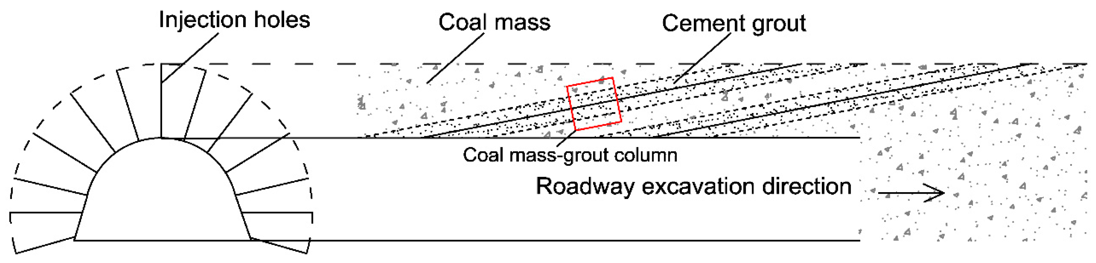
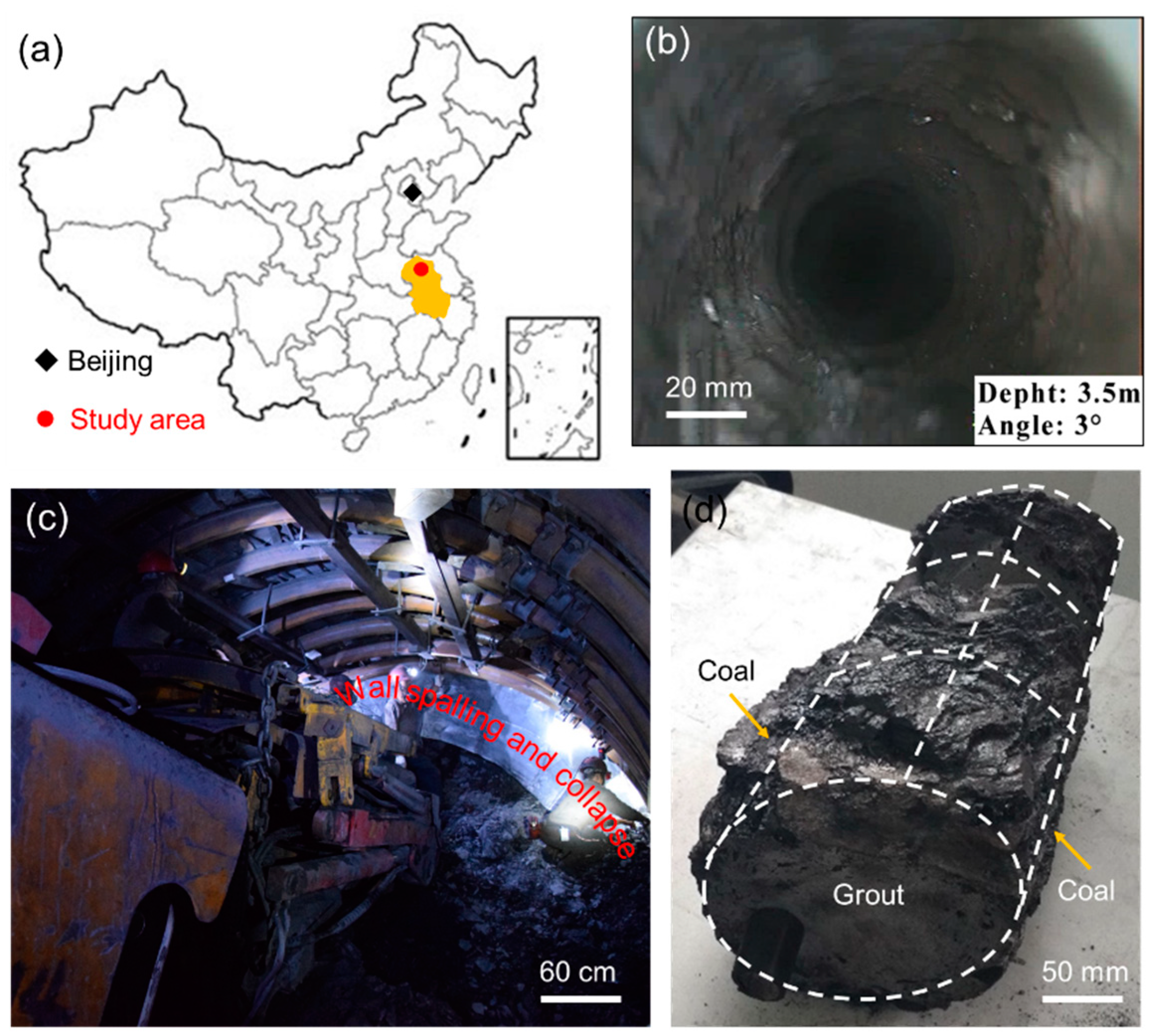
2. Field Observation

The Guobei coal mine is located in the Huaibei Coalfield, in East China (Figure 2a) [29]. The extremely soft coal mass was observed in the No. 8 seam with the burial depth around 800 m, which is full of fractures and cracks (Figure 2b). The phenomenon of coal spalling and collapse was normally encountered at roadway working face because of the driving-induced stress and the poor quality of coal mass (Figure 2c) [30]. In addition, the present U-shaped shed support scheme cannot control the large displacement of roadway effectively, resulting in high maintenance costs. Accordingly, a pre-grouting technique was used to try to improve the strength of coal mass before driving the roadway in the field. The grouting material was P.O.325 with a water–cement ratio of 0.7 [31]. The grouting pressure was less than 4 MPa, normally around 2 MPa. After excavation, the typical consolidated structure of the coal-grout pile is shown in Figure 2d, indicating that the grout into such soft coal mass is compaction grouting instead of permeation grouting. The grouting diffusion radius was limited, but the coal around the grout was compacted. A schematic diagram of soft coal mass after grouting is shown in Figure 3. Hence, to qualitatively evaluate the effect of grouting for such coal mass, a reasonable model containing coal boundary and grout was presented, and its overall strength was assessed by direct shear tests.

3. Experimental Methodology

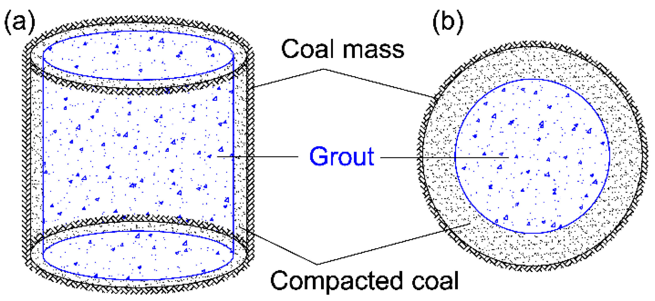
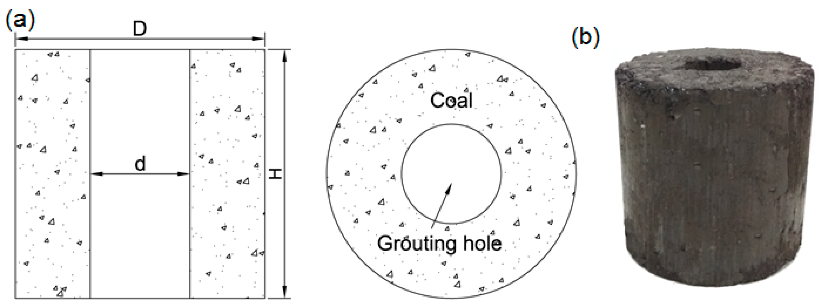
3.1. Sample Preparation

Considering the field observation of cement grouting, a composite of the coal-grout specimen was designed and prepared to investigate the influence of grouting on soft coal mass. The specimen before grouting is shown in Figure 4. Both the outside diameter (D) and the height (H) of specimens are constant, 50 mm. The diameter of the inner grouting hole (d) is varied from 0 to 50 mm, in which it will be filled with cement grout (Figure 4a). To construct the external annulus of specimens (Figure 4b), a vertical load equivalent to in situ stress condition was applied to the fine-size coal collected from the driving roadway. Although the model we used may not perfectly represent the field conditions, it still provides a comparable way to investigate the reinforcement effect of compacting grouting on coal mass. To assess this, the grouting ratio (d/D) was defined, expressing the ratio of grout diameter (d) to the outside diameter (D) of the specimen.

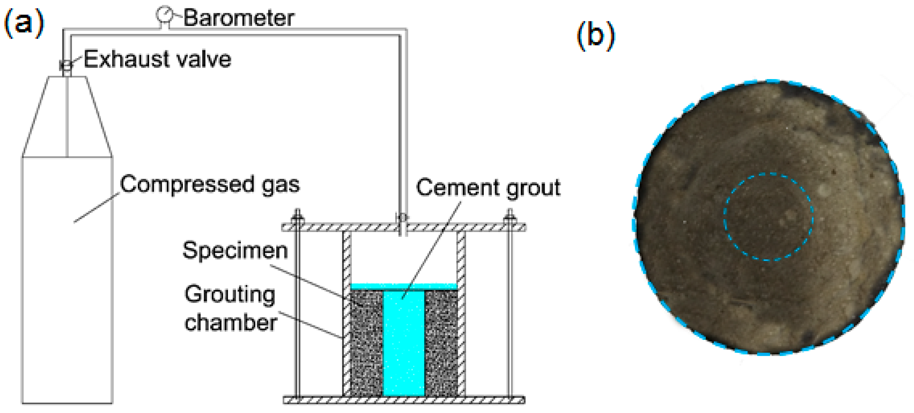
3.2. Grouting Procedure

To inject the cement grout into coal samples with pressure, an indoor grouting test system composed of a grouting chamber and pressure source was designed (Figure 5a). The grouting chamber was assembled by steel plates and bolts. Rubber seal was used for ensuring the airtightness between the steel plates. The pressure source was a nitrogen cylinder filled with compressed air to provide pressure for grouting. The cement used in this study was a locally available P.O. 325 with water reducer to improve the fluidity of the mix. The water–cement ratio (w:c) of the grout was 0.7. The coal sample was loaded into the grouting chamber, and then the prepared cement paste was poured into the inner hole until covering the top surface of the coal sample. After that, the grouting chamber was closed and sealed by bolts. The exhaust valve was opened, and the high-pressure gas entered the grouting chamber for further improving the consolidation of the grout. The pressure was kept at 1 MPa for 1 h. After grouting, the samples were cured for 28 days in a curing room at constant temperature and humidity (Figure 5b). The basic experiment of coal and grout such as compression tests was conducted. The compressive strength (UCS) of coal and cement paste (28 days’ strength) is 2.5 MPa and 7.2 MPa, respectively.

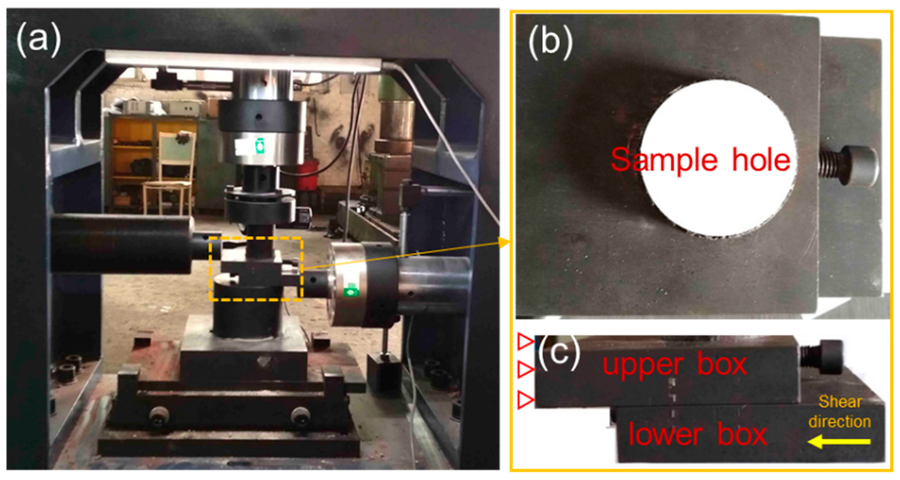
3.3. Shear Tests Design

The shear tests of coal and grouted coal specimens were conducted using a servo-hydraulic direct shear apparatus (Figure 6a). The maximum horizontal shear displacement of the machine is 20 mm, gauged by a sensor with an accuracy of 0.001 mm. The normal/horizontal loading rate and their corresponding velocities can be chosen in the range of 0.01–2 kN/s, 0.001–2 mm/s, respectively. A special shear box was designed and manufactured to be used for shear test (Figure 6b,c). During the tests, the upper box is fixed and the lower box can be moved.
The shear tests of pure coal and grouted coal specimens were examined according to Table 1. To reveal the effect of grouting ratio (d/D) on the shear behavior of reinforced samples, the different diameters of grouting holes were designed as 0, 10, 20, 30, 50 mm, corresponding to grouting ratio, d/D of 0, 20, 40, 60, 100%, respectively. During the shear tests, normal loading was applied at 0.05 kN/s to a set value, then held constant. The magnitude of the normal load was divided into three catalogs, i.e., 1.0 kN, 1.5 kN, and 2.0 kN (given in Table 1). A shear load subsequently was applied with displacement control at a rate of 0.05 mm/s. All calculations have been done based on the standard test method for performing laboratory direct shear tests (ASTM D5607).

4. Experimental Results

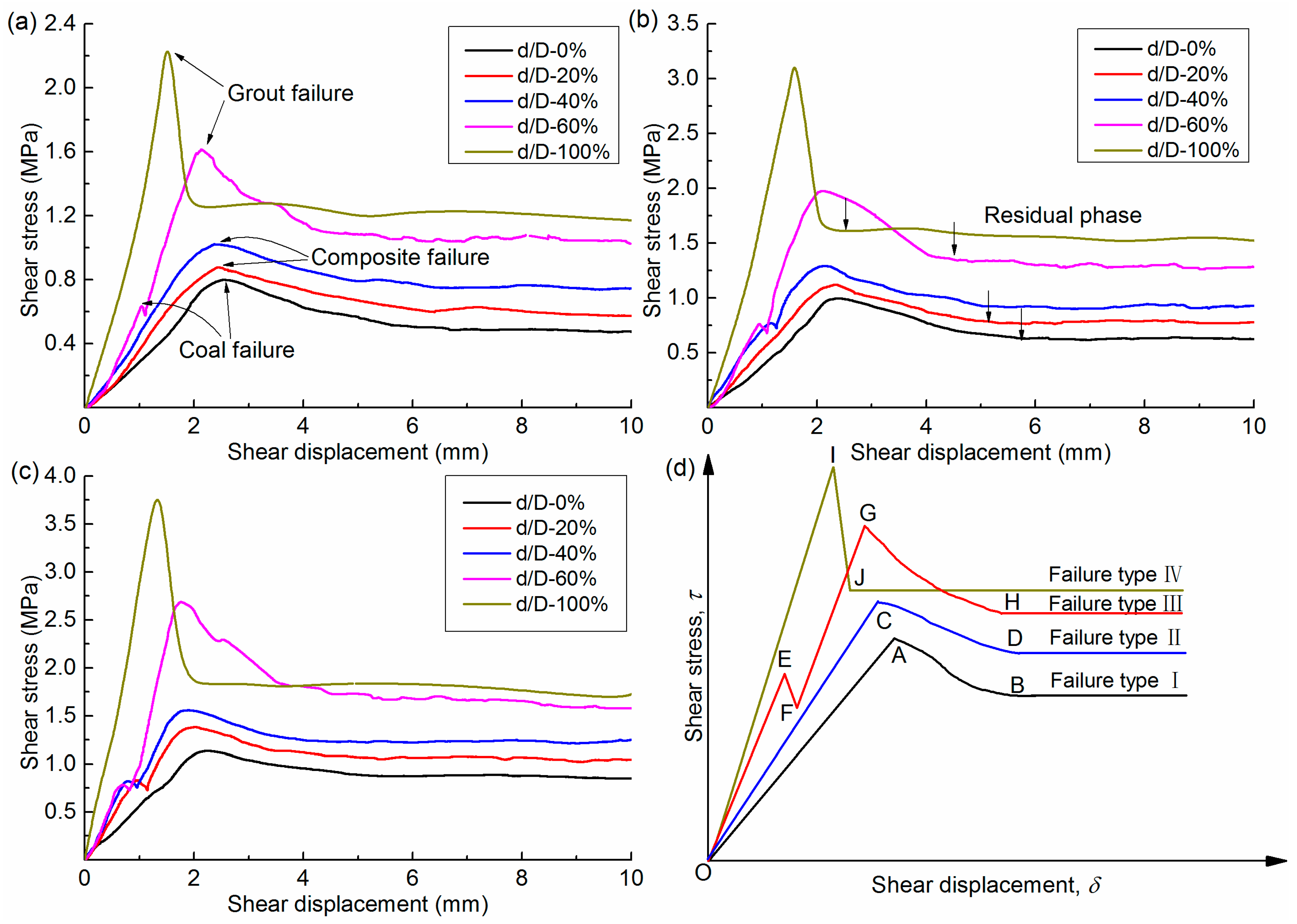
4.1. Shear Behavior and Failure Modes

The shear stress versus shear displacement curves for different grouting ratios (d/D) under different normal stresses is illustrated in Figure 7. In general, both the peak and residual shear stress increased and the peak shear displacement decreased with increasing d/D and normal stress. Figure 7a depicts the shear stress-displacement curves under lower normal stress σn, 0.51 MPa. The shear stresses in the curves of d/D, 0%, 20%, 40% rose slowly until peak stress and then decreased gradually to a residual level. The peak shear stresses for pure coal samples and coal-grout samples signified the coal failure and composite failure, respectively. As the grouting ratio increased, even for lower normal stress, multi-stage failure can be observed. For the high d/D, 60%, there were two peak stress values, showing the non-simultaneous failure properties for grouted coal samples. The first and the second peak shear stress correspond to the failure of coal and failure of grout, respectively. Under the normal stress 0.51 MPa, the maximum peak shear stresses were 0.79, 0.88, 0.99, 1.61, 2.24 MPa for d/D, 0, 20, 40, 60, and 100%, respectively. Figure 7b (σn, 0.77 MPa) and Figure 7c (σn, 1.02 MPa) exhibited similar trends like that in Figure 7a. However, the number of curves of multi-stage failure modes increased with increasing normal stress. In Figure 7b, the maximum shear stresses of d/D, 0, 20, 40, 60, 100% were 0.99, 1.12, 1.29, 1.97, 3.18 MPa, respectively. Under the normal stress of 1.02 MPa, compared with shear stresses for grouting ratio d/D, 0%, the shear stress values of d/D, 20, 40, 60, 100% increased by 13.1, 27.1, 118, 241%, respectively. It should be pointed out that, though it is difficult to inject 100% cement grout into soft coal mass in real condition, testing the strength properties of pure grout samples (with grouting ratio of 100%) is helpful to understand the failure mechanism of coal-grout structure. It can be seen that, with the increase of the normal stress, the peak shear stress and residual stress increase.
A simplified sketch is depicted in Figure 7d to highlight key features in the shear stress-displacement curves. Three typical failure modes of coal and grouted coal were revealed. The failure type I represented the single-stage instability that can be observed in pure coal samples only. The shear stress increased to peak shear stress (A), then it declined to a residual value (B). During this process, coal was the only medium to resist the shear force. Type II had a trend similar to the first failure mode, but it had a higher peak shear stress (C) with lower displacement (D). It can be observed in the grouted coal specimen when normal stress and/or grouting ratio decreased. In this case, the coal and grout resisted the shear force and failed as a stable combination (composite failure). The failure type III was characterized by two peak shear stresses that can be observed, especially when normal stress and/or grout percentage increased. In the third type (multi-stage failure), the shear stress increased steeply to the first peak stress (E), wherein it represented the occurrence of the coal failure, and stress dropped suddenly (F). Then the sample continued to resist the shearing. Shear stress increased sharply again until the second peak stress value (G), owing to the grout failure, followed by a decreasing phase to the ultimate shear strength (H). As for failure type IV, it represents the pure grout failure during shear. The shear stress increases quickly within small shear displacement to the peak point (I) and then drops sharply to residual point (J).
To understand the rupture of the coal-grout structure clearly, a classical division of rupture mechanism (shown in Figure 8) was introduced according to the recommendation in the previous literature [32,33]. From Figure 8, the generalization rupture classification is dependent on the ratio of normal stress to compressive strength, i.e., σn/UCS. Normally, the rupture criteria of hard rock (UCS = 54 MPa) by the direct shear test are defined as follows: at low ratios (σn/UCS < 0.16), specimens rupture in a predominantly tensile splitting mode as Class T; at medium ratios (0.17 < σn/UCS < 0.41), shear rupture via en echelon tensile fracture arrays as Class ET; at high ratios (0.41 < σn/UCS < 0.46), specimens rupture progressively in a mixed-mode or transition between Class T and ET, as Class M [34].
The coal-grout structure may exhibit distinctive rupture modes, because the UCS of the specimen (coal and cement grout) is much smaller than the rock. It is important to classify the rupture modes of coal and grout clearly in this study. According to the test results in Figure 7, the rupture of coal (0.19 < σn/UCS < 0.41) belongs to Class M. Its idealized load-displacement shows that the load transfers from slightly strain-weakening behavior to elastic-plastic behavior. For the grout in coal-grout structure, the σn/UCS is from 0.003 to 0.051, and its rupture modes belong to Class ET (shown in Figure 7). As we can see, the rupture of coal and grout is different from that of rock. The possible reason can be summarized as follows: the combination of the coal-grout structure is different from the rock materials. Based on the experiments, the coal normally fails firstly, and during its failure process, the microfractures in grout have developed, propagated and even coalesced. Then, after the coal rupture, more fractures would occur and be connected, but the grout rupture would not be sudden, as the fractures have already connected slightly during the process of coal failure. Hence, the rupture of grout in this study exhibits a strain-weakening with a less rapid stress drop post-peak. As for coal in coal-grout structure, due to the strength being too low, the residual strength could not drop obviously, leading to the idealized load-displacement behavior transitioning from slightly strain-weakening to elastic-plastic. Based on the shear test curves of pure grout (Figure 7), the rupture of pure grout (0.071 < σn/UCS < 0.142) belongs to Class T, its idealized load-displacement behavior shows a sudden drop when reaching peak shear stress, exhibiting a tensile splitting mode. The failure modes and rupture mechanism of the specimens observed from the direct shear tests are summarized in Table 2.
Besides, it should be pointed out that, in this study, the shear behavior and failure modes of the coal-grout structure were obtained under constant normal load (CNL) condition. As we can see from Figure 7, the normal stress was set as a constant during each test (i.e., 0.51 MPa, 0.77 MPa, and 1.02 MPa). However, the shear strength of the coal-grout structure could be also influenced by constant normal stiffness (CNS) boundary condition. When suffering shear stress, the surrounding coal mass in the underground may exhibit an obvious dilatant deformation, but the deformation of coal mass may be restrained by support structures, leading to an increase of normal (i.e., confining) stress. This phenomenon can be represented by the CNS boundary condition. In this case, the shear strength of the coal-grout structure measured in CNS direct shear would be much larger compared with that measured in CNL shear according to the results in the literature [35]. Besides, the stress-displacement curves in CNS shear may exhibit a clear yield behavior and elastic behavior dominated prior to the yield stage, while stress-displacement curves of CNL shear exhibited none or small yield strength before peak shear strength based on the previous study [36].

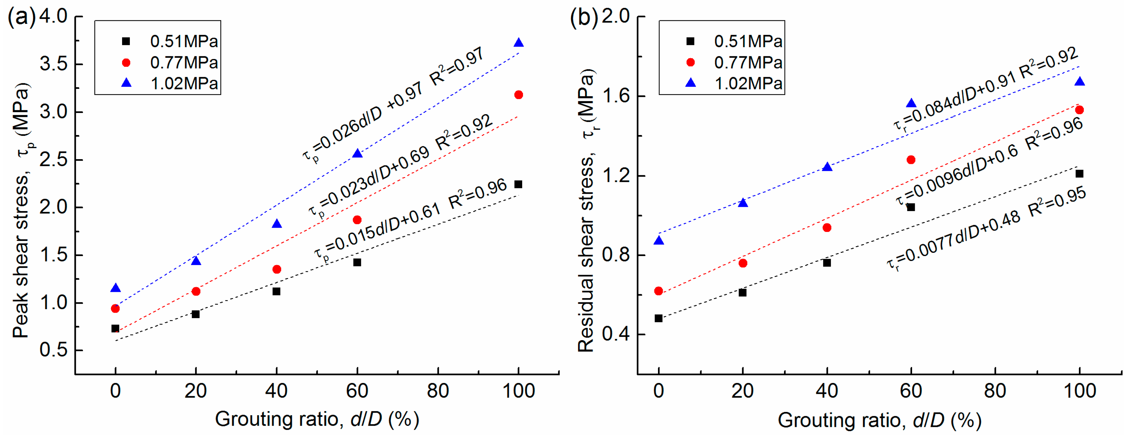
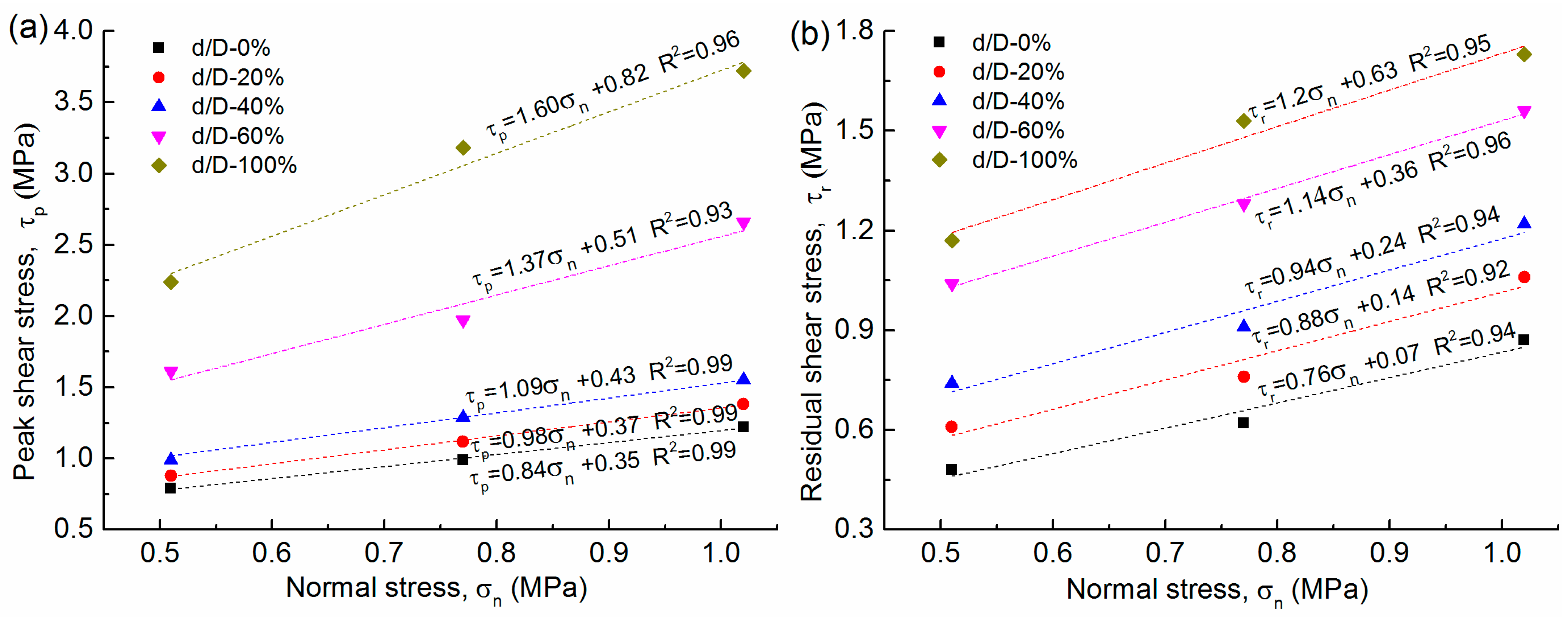
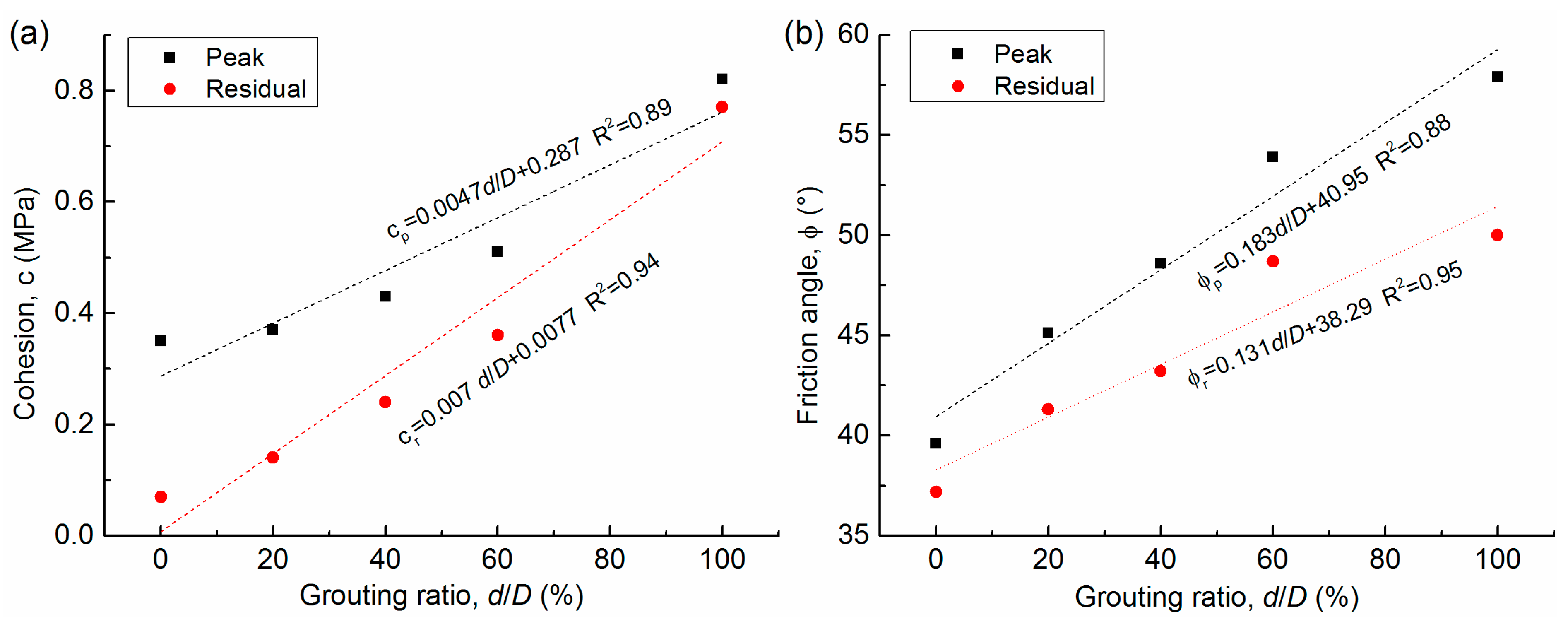
4.2. Shear Strength Characteristics

The effect of grout on peak and residual shear stress of specimen for different normal stresses is shown in Figure 9. It can be observed that both the maximum peak and residual shear stress increased with the increase in the grouting ratio under different normal stress levels (0.51 MPa, 0.77 MPa, and 1.02 MPa). A linear regression analysis was carried out to investigate the relation between shear stress and the grouting ratio. The coefficients R2 of fitting lines were greater than 0.9, showing a strong relevance.
Figure 10 shows the shear test results grouped by different grouting ratios in the shear stress-normal stress space. The relation between both peak/residual shear stresses and normal stresses was linearly fitted by the Mohr–Coulomb failure envelope. (Equations (1) and (2))
τp = σn·tan(φp) + cp
τr = σn·tan(φr) + cr
where τp, τr, φp, φr, cp, cr and σn are the peak shear stress, residual shear stress, peak friction angle, residual friction angle, peak cohesion, residual cohesion, and normal stress component, respectively.
According to the linear fitting data in Figure 10a,b, the coefficients of determination were greater than 0.92, illustrating that the failure of coal, pure grout and grouted coal specimen followed the Mohr–Coulomb failure criterion well when they suffered the normal and shear stresses. The calculated peak and residual cohesion and friction angle are summarised in Table 3.
To quantify the relations between the amount of grout and shear strength for coal and grouted specimens, simple regression models were conducted (shown in Figure 11). The results indicated that there was a strong correlation between grout percent d/D and the peak/residual strength parameters (cohesion and friction angle). The established formulas for the prediction of peak/residual cohesion and friction angle are shown in Figure 11a,b, respectively. With the increase in the amount of grout, the cohesion and friction angle of composite samples increased evidently, quantitatively implying that grouting can significantly enhance the strength of coal mass. The relevance mechanism of strength improvement by grouting can be concluded as follows:
For failure type II, the coal and grout suffer the shear strength together and the combined effect of the non-homogeneous coal and grouted column plays a key role in this process. As for failure type III, before the coal failure, the coal and grout bear the shear stress together and then with the increase of the shear displacement, the coal fails and the grout suffers the shear strength only. Due to the relative higher strength of the grout, the overall strength of the coal-grout exhibits higher shear stress.

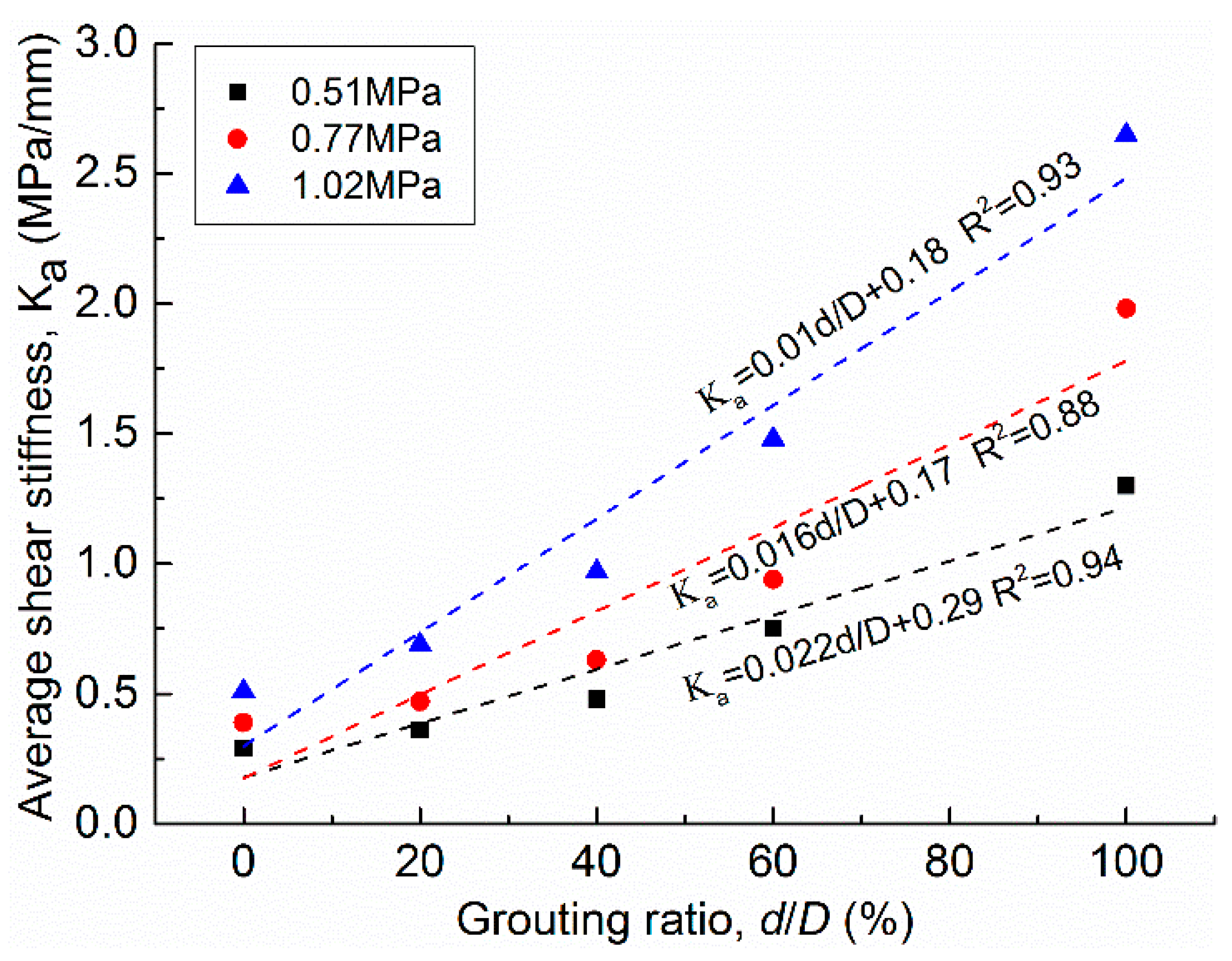
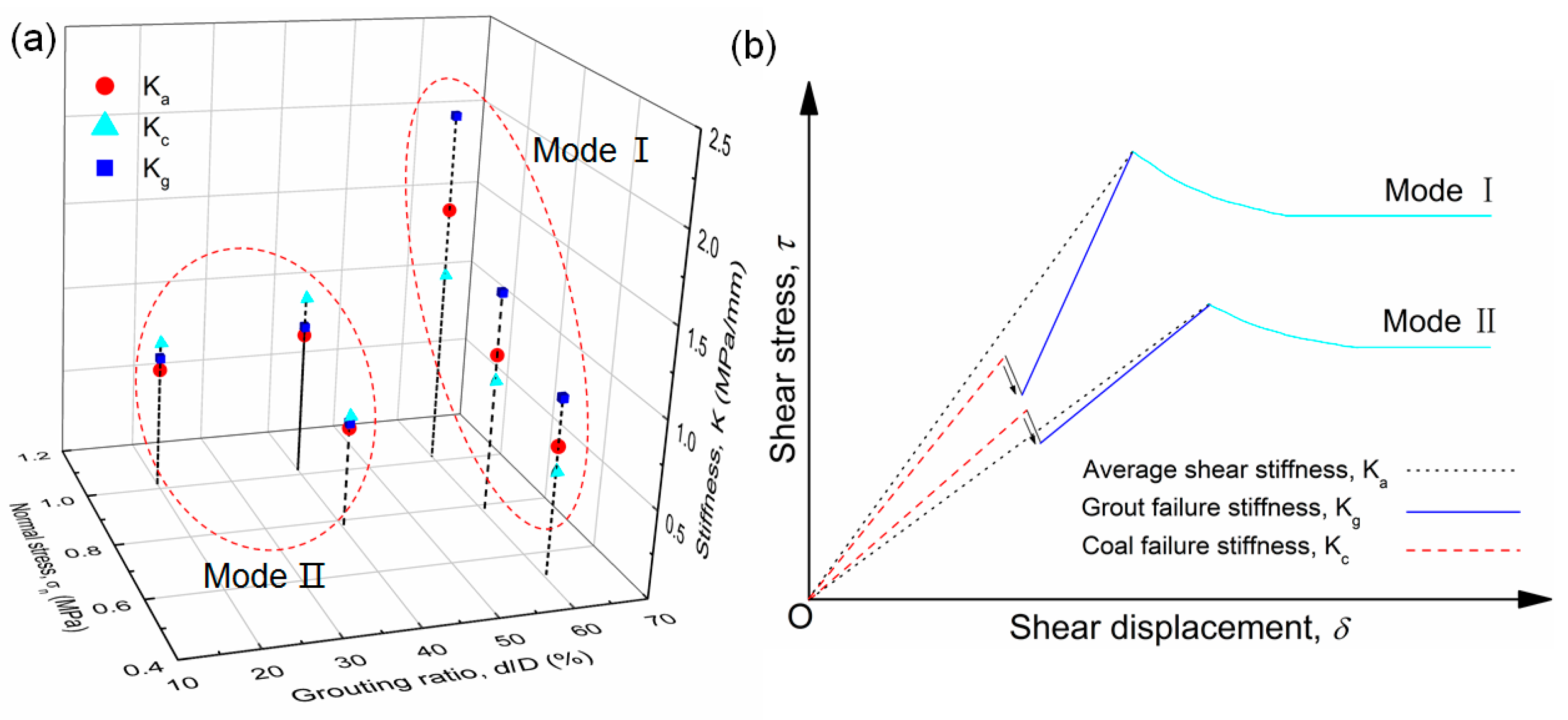
4.3. Shear Stiffness Properties

The deformation behavior of coal and grout coal composite can be characterized by its shear stiffness. It represents the capacity of resistance in shearing. The average shear stiffness Ka is defined as follows: The maximum shear stress divides by the corresponding displacement. The relation between grouting ratio (d/D) and Ka for coal and grouted coal specimens is illustrated in Figure 12. A linear relation between Ka and d/D was illustrated by fitting lines. The coefficients of determination show that they were in strong relevance.
Furthermore, the shear stiffness for each curve in multi-stage failure mode (type III) can be divided into coal failure stiffness (Kc) and grout failure stiffness (Kg), respectively. The stiffness results including Kc, Kg, and Ka for different d/D and normal stresses in failure type III are illustrated in Figure 13a. For the grouting ratio d/D (60%), it shows that Kg > Ka > Kc (mode I). As for the relatively low d/D (20%, 40%), it shows that Kc > Kg > Ka (mode II).
The two stiffness modes in failure type III are schematically shown in Figure 13b. The phase of sudden stress drop reduced the overall stiffness of samples evidently. Grout failure stiffness Kg determined the average failure stiffness Ka. This means that increasing the amount of grout in samples could obtain higher Ka, otherwise not. The stiffness mode I can be observed under high d/D. Although higher d/D resulted in the stress drop more easily (described in Section 4.1), the Ka is higher than Kc, which signifies that grouting improved the overall stiffness of coal. The failure stiffness model II can be found under low d/D, showing that the Ka is lower than Kc. It illustrates that less grout cannot take over the shear deformation of grouted coal completely. The stress drop is unfavorable for the overall stability of the coal-grout structure, especially under the low grouting ratio.

5. Discussion

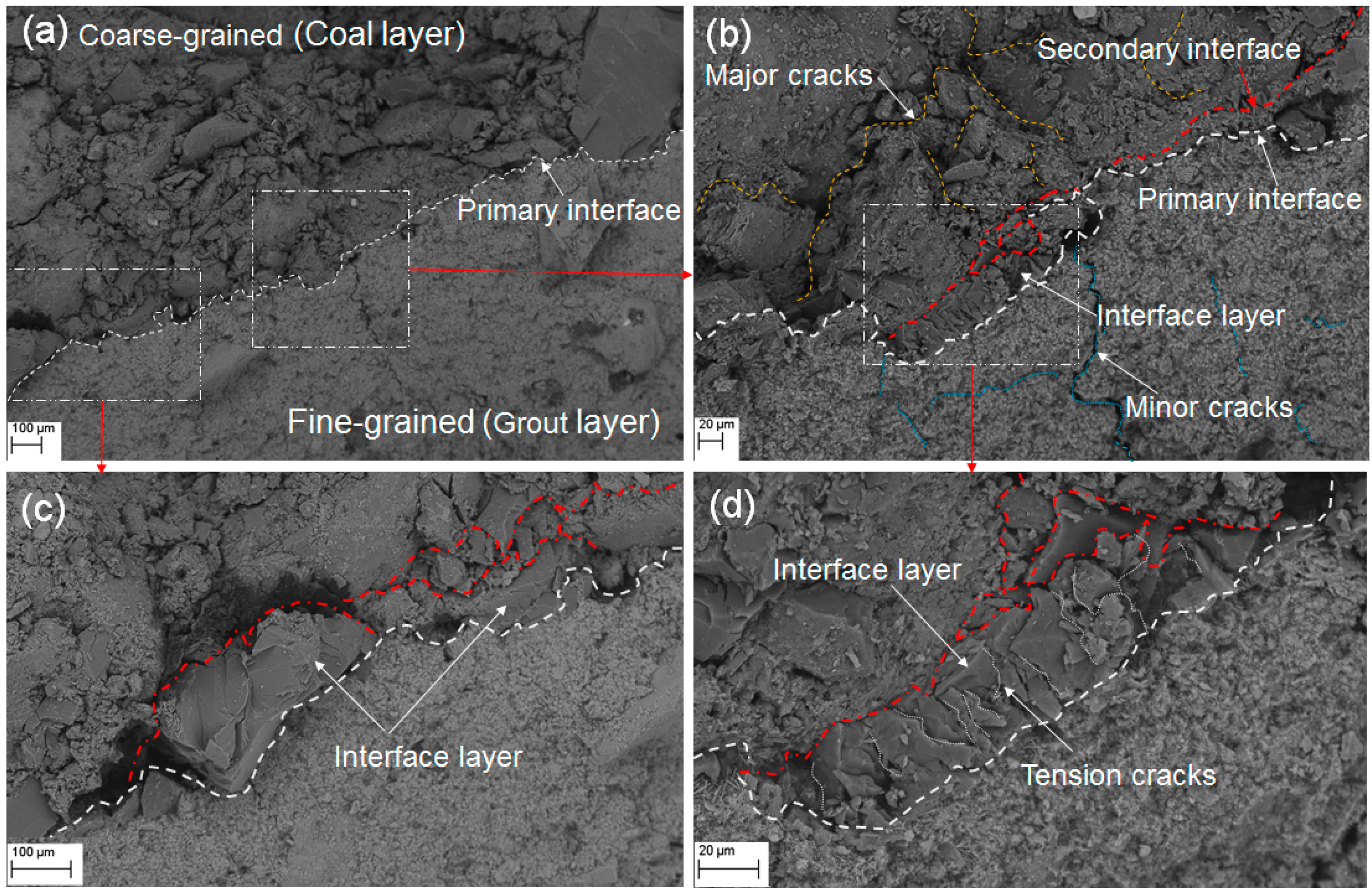
5.1. Microstructure of the Coal–Grout Interface

The overall shear strength and stiffness of grouted coal is affected by the interface between coal and grout. Analyzing the microscopic interfacial structure is helpful to reveal the failure mechanism of the specimen. The scanning electron microscopic (SEM) image on the surface of grouted coal is shown in Figure 14. As illustrated in Figure 14a, there was a primary interface between the coarse-grained coal layer and the fine-grained grout layer. The primary interface was not completely surface contact, but instead comprised irregular point contacts that could result in a relatively weak and discontinuous bonding force. Furthermore, microscopic observations indicated that there was an intermittent secondary interface near the coal layer (Figure 14b). It contained one or more interface branches. Between the primary interface and secondary interface, the intermediate layer like a “transition zone” was generated (shown in Figure 14b–d). Besides, the two mediums considerably differed from each other in microcracks. As shown in Figure 14b, many major cracks were in the coal layer between coal particles and coal matrix, compared with a few minor cracks in the grout layer. This indirectly verified the reason why grout has higher strength and stiffness when it suffers shearing.
From Figure 14c,d, two typical statuses of the interface layer were revealed. One is a relatively complete layer consisting of the large coal grains and coal matrix (Figure 14c). Another is a cracked layer subjected to the tension that resulted in many tiny cracks in the coal matrix (Figure 14d). The secondary interface could be viewed as a series of coal failures near the primary interface, which formed after the primary interface. The bonding force between the coal layer and grout layer was created when cement grout solidified. Furthermore, micro shrinkage of cement would occur during this curing process, leading to micro-tension between grout and coal. When the micro-tension exceeded the ultimate tensile stress in coal or the cohesive strength between coal grains and coal matrixes, the different failure patterns in the interface layer would engender. The interface layer of grouted coal observed in this study is different from the interfacial transition zone (ITZ) investigated by [37,38]. ITZ is the interface between cement pastes and aggregates, which has a higher porosity and fills with the deposition of hydration products [39,40]. The “coal-grout interface layer” can be seen as an intermediate layer filled with crushed coal between the grout layer and a relatively stable coal layer. When the coal-grout structure suffered high stress, the irregularly cracked interface layer failed easily, which induced the stress drop and affected the overall stability of grouted coal.

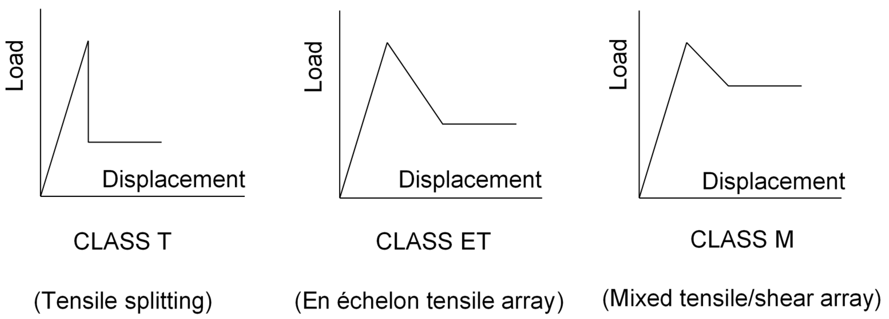
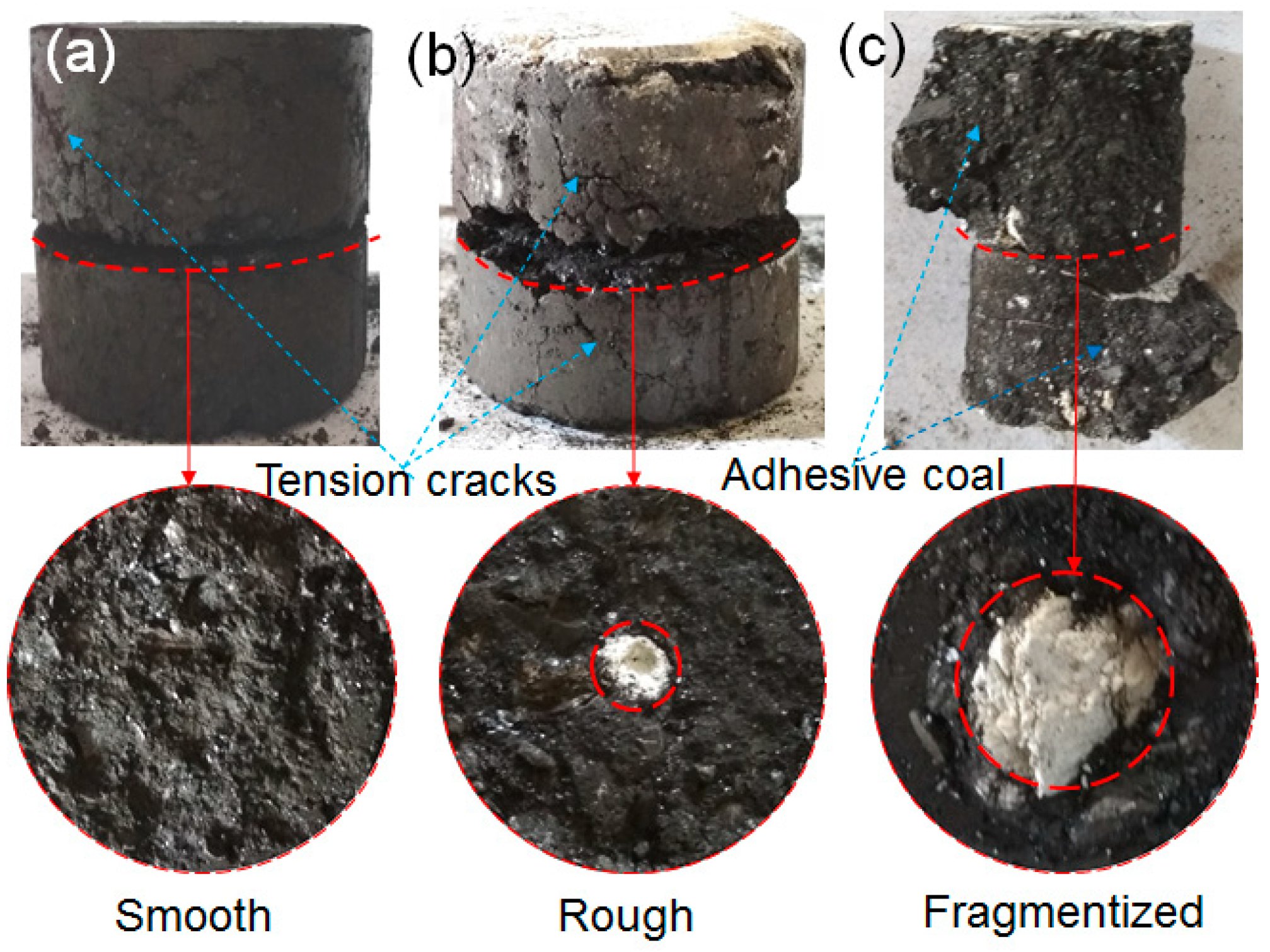
5.2. Macroscopic Failure Characteristics

The failure process of a rock or coal sample can be seen as a successive evolution of cracks at the mesoscopic level [41,42]. As for the coal and grouted coal, the appearance, propagation, and coalescence of mesoscopic cracks resulted in their failure, when they suffered shearing. Figure 15 shows images of typical failure patterns of the specimen after shear tests. As described above, there were three typical failure modes for coal and grouted coal. In Figure 15a, it illustrates a smooth shear plane in pure coal sample, corresponding to the failure type I. The composite failure type II for the grouted coal is depicted in Figure 15b. A relatively rough shear plane was formed. Tension cracks can be found on the surface from both Figure 15a,b. Based on the shear stress-displacement curves for failure I and II, a gentle process by the development and coalescence of cracks in coal and grout can be deduced during the shearing. When grout percentage and/or normal stress increased, the failure of the specimen is shown in Figure 15c, which corresponds to the failure type III. The coal around the solidified grout was fragmentized. A small part of coal stuck on the surface. The “coal-grout interface layer” described above became weak and crushed when it suffered high stress. In this case, the combination of coal and grout was no longer stable. Hence, the cracks in external coal coalesced and failed, then the fragmentized interface layer induced a stress drop followed by the propagation and coalescence of cracks in the grout. It is characterized by multi-stage failure (or non-simultaneous failure).

5.3. Suggestions for Cement Pre-Grouting in Soft Coal Mass

As discussed above, the cement grouting can significantly improve the strength and stiffness of soft coal. The formed cement column can be seen as effective support for compacted surrounding coal mass. The overall mechanical parameters (strength, stiffness, cohesion and friction angle, etc.) of grouted coal can be predicted by the linear regression formulas we proposed in this paper. In practice, according to the effective compacting grouting diameter, the overall strength and stiffness of grouted coal mass in a certain range can be identified. In this case, the safe and economic pre-grouting parameters such as the number of grout holes and the amount of grout can be designed qualitatively instead of designing by experience.
Moreover, the cracked interface layer between coal and cement grout played a negative effect based on the analysis of the microscopic coal-grout structure and the macroscopic failure characteristics of the specimen. The failure is characterized by the sudden stress drop and decline of strength and stiffness. The possible reason is that the relatively large cement grains could not penetrate the coal layer effectively. Some point contacts between cement and coal resulted in a potentially unstable bonding structure. The main function of cement consolidation grouting is to improve strength for large fractures and cracks in coal mass instead of micro-cracks [43]. On the other hand, the shrinkage of cement resulted in a “broken zone” called “coal-grout interface layer”. The crushed interface layer affected the overall stability of the coal-grout structure. Cement drying shrinkage significantly affected the durability and integrity of a structure [44,45]. To solve the shrinkage problem, shrinkage-compensating cement can be used to fill the gaps and enhance structural stability over ordinary cement [46,47]. Also, the use of cement grouts containing supplementary cementitious materials (SCMs) is also an effective way to solve the shrinkage [48,49]. Therefore, in the field, ultra-fine cement, the shrinkage-compensating or SCMs cement could be good choices for pre-grouting to further improve the stability of grouted coal mass.

6. Conclusions

In this study, according to the field observation of cement grouting into soft coal mass, a coal-grout structure was presented. Through a series of direct shear tests for coal and grouted coal specimens, the effect of grouting on coal mass was quantitatively revealed. The influence of grouting ratio (d/D of 0. 20, 40, 60%) on the shear behaviors were studied. A set of formulas were proposed for predicting the mechanical parameters of grouted soft coal mass. The failure modes of coal and grouted coal were systematically analyzed. The micromorphology interface of the coal-grout structure and its impact on macroscopic failure properties of the specimens were discussed. Finally, the application of prediction models and some measures for further improving the overall mechanical properties of grouted coal mass were suggested. The main conclusions can be summarized as follows:
Both the peak and residual shear stresses of grouted coal mass increased and the peak shear displacement decreased with the increase of grouting ratio and normal stress. Three failure types were proposed according to the failure time of coal and grout. Different failure modes depended on the grouting ratio and normal stress.
Linear relations between the peak/residual shear stress and grouting ratio were established, which quantitatively verified the effect of cement grouting on soft coal mass. The vital strength parameters (peak/residual cohesion and friction angle) of grouted coal mass can be predicted by the constructed models.
The average shear stiffness of grouted coal increased linearly with the increase in the grouting ratio. Two typical shear stiffness modes in failure “type III” for grouted coal were revealed, signifying that the sudden stress drop reduced the overall stiffness of grouted coal mass evidently.
The “coal-grout interface layer” generated by shrinkage of cement had a negative effect on the stability of the coal-grout structure. Combining the analysis of microscopic bonding properties and macroscopic failure performance of grouted coal, the use of ultra-fine cement, shrinkage-compensating or SCMs cement could be better choices for further stabilizing the soft coal mass.

Author Contributions

Conceptualization by Y.S. and G.L.; methodology, J.H.; investigation, J.Z.; writing—original draft preparation, Y.S.; writing—review and editing, G.L., J.S., J.Z., R.T.; supervision, G.L.; funding acquisition, G.L., R.T. All authors have read and agreed to the published version of the manuscript.

Funding

This research was supported by the projects of “the Fundamental Research Funds for the Central Universities (2021QN1003, 2020ZDPY0221)”, “National Natural Science Foundation of China (52104106, 52174089)”.

Institutional Review Board Statement

Not applicable.

Informed Consent Statement

Not applicable.

Data Availability Statement

The data presented in this study are available on request from the corresponding author. The data are not publicly available due to privacy.

Acknowledgments

The authors are grateful to Huaibei Mining (Group) Co. Ltd. Special thanks to Zuqi Wang for her encouragements.

Conflicts of Interest

The authors declare no conflict of interest.

References

  1. Yang, H.; Zhang, N.; Han, C.; Sun, C.; Song, G.; Sun, Y.; Sun, K. Stability Control of Deep Coal Roadway under the Pressure Relief Effect of Adjacent Roadway with Large Deformation: A Case Study. Sustainability 2021, 13, 4412. [Google Scholar] [CrossRef]
  2. Yang, H.; Han, C.; Zhang, N.; Sun, Y.; Pan, D.; Sun, C. Long high-performance sustainable bolt technology for the deep coal roadway roof: A case study. Sustainability 2020, 12, 1375. [Google Scholar] [CrossRef] [Green Version]
  3. Sun, C.; Li, G.; Gomah, M.E.; Xu, J.; Sun, Y. Creep characteristics of coal and rock investigated by nanoindentation. Int. J. Min. Sci. Technol. 2020, 30, 769–776. [Google Scholar] [CrossRef]
  4. Kang, Y.; Liu, Q.; Xi, H.; Gong, G. Improved compound support system for coal mine tunnels in densely faulted zones: A case study of China’s Huainan coal field. Eng. Geol. 2018, 240, 10–20. [Google Scholar] [CrossRef]
  5. Zolfaghari, A.; Sohrabi Bidar, A.; Maleki Javan, M.R.; Haftani, M.; Mehinrad, A. Evaluation of rock mass improvement due to cement grouting by Q-system at Bakhtiary dam site. Int. J. Rock Mech. Min. Sci. 2015, 74, 38–44. [Google Scholar] [CrossRef]
  6. Sun, Y.; Li, G.; Basarir, H.; Karrech, A.; Azadi, M.R. Laboratory evaluation of shear strength properties for cement-based grouted coal mass. Arab. J. Geosci. 2019, 12, 690. [Google Scholar] [CrossRef]
  7. Brantberger, M.; Stille, H.; Eriksson, M. Controlling grout spreading in tunnel grouting—analyses and developments of the GIN-method. Tunn. Undergr. Sp. Technol. 2000, 15, 343–352. [Google Scholar] [CrossRef]
  8. Fang, Q.; Du, J.; Li, J.; Zhang, D.; Cao, L. Settlement characteristics of large-diameter shield excavation below existing subway in close vicinity. J. Cent. South Univ. 2021, 28, 882–897. [Google Scholar] [CrossRef]
  9. Mou, B.; Bai, Y. Experimental investigation on shear behavior of steel beam-to-CFST column connections with irregular panel zone. Eng. Struct. 2018, 168, 487–504. [Google Scholar] [CrossRef]
  10. Sun, J.; Huang, Y.; Aslani, F.; Ma, G. Properties of a double-layer EMW-absorbing structure containing a graded nano-sized absorbent combing extruded and sprayed 3D printing. Constr. Build. Mater. 2020, 261, 120031. [Google Scholar] [CrossRef]
  11. Sun, J.; Lin, S.; Zhang, G.; Sun, Y.; Zhang, J.; Chen, C.; Morsy, A.M.; Wang, X. The effect of graphite and slag on electrical and mechanical properties of electrically conductive cementitious composites. Constr. Build. Mater. 2021, 281, 122606. [Google Scholar] [CrossRef]
  12. Sun, J.; Aslani, F.; Wei, J.; Wang, X. Electromagnetic absorption of copper fiber oriented composite using 3D printing. Constr. Build. Mater. 2021, 300, 124026. [Google Scholar] [CrossRef]
  13. Li, H.Y. Major and minor structural features of a bedding shear zone along a coal seam and related gas outburst, Pingdingshan coalfield, northern China. Int. J. Coal Geol. 2001, 47, 101–113. [Google Scholar] [CrossRef]
  14. Basarir, H.; Sun, Y.; Li, G. Gateway stability analysis by global-local modeling approach. Int. J. Rock Mech. Min. Sci. 2019, 113, 31–40. [Google Scholar] [CrossRef]
  15. Sun, Y.; Li, G.; Zhang, J.; Qian, D. Stability Control for the Rheological Roadway by a Novel High-Efficiency Jet Grouting Technique in Deep Underground Coal Mines. Sustainability 2019, 11, 6494. [Google Scholar] [CrossRef] [Green Version]
  16. Sun, Y.; Zhang, J.; Li, G.; Wang, Y.; Sun, J.; Jiang, C. Optimized neural network using beetle antennae search for predicting the unconfined compressive strength of jet grouting coalcretes. Int. J. Numer. Anal. Methods Geomech. 2019, 43, 801–813. [Google Scholar] [CrossRef]
  17. Sun, Y.; Zhang, J.; Li, G.; Ma, G.; Huang, Y.; Sun, J.; Wang, Y.; Nener, B. Determination of Young’s modulus of jet grouted coalcretes using an intelligent model. Eng. Geol. 2019, 252, 43–53. [Google Scholar] [CrossRef]
  18. Li, S.; Han, W.W.; Zhang, Q.; Liu, R.; Weng, X. Research on time-dependent behavior of viscosity of fast curing grouts in underground construction grouting. Chin. J. Rock Mech. Eng. 2013, 32, 1–7. [Google Scholar]
  19. Sun, Y.; Li, G.; Zhang, J. Developing Hybrid Machine Learning Models for Estimating the Unconfined Compressive Strength of Jet Grouting Composite: A Comparative Study. Appl. Sci. 2020, 10, 1612. [Google Scholar] [CrossRef]
  20. Sun, Y.; Li, G.; Zhang, J. Investigation on jet grouting support strategy for controlling time-dependent deformation in the roadway. Energy Sci. Eng. 2020, 8, 2151–2158. [Google Scholar] [CrossRef] [Green Version]
  21. Sun, Y.; Li, G.; Zhang, J.; Qian, D. Experimental and numerical investigation on a novel support system for controlling roadway deformation in underground coal mines. Energy Sci. Eng. 2020, 8, 490–500. [Google Scholar] [CrossRef] [Green Version]
  22. Kikuchi, K.; Igari, T.; Mito, Y.; Utsuki, S. In situ experimental studies on improvement of rock masses by grouting treatment. Int. J. Rock Mech. Min. Sci. 1997, 34, 138-e1. [Google Scholar] [CrossRef]
  23. Huang, J.; Zhang, Y.; Sun, Y.; Ren, J.; Zhao, Z.; Zhang, J. Evaluation of pore size distribution and permeability reduction behavior in pervious concrete. Constr. Build. Mater. 2021, 290, 123228. [Google Scholar] [CrossRef]
  24. Huang, J.; Duan, T.; Zhang, Y.; Liu, J.; Zhang, J.; Lei, Y. Predicting the permeability of pervious concrete based on the beetle antennae search algorithm and random forest model. Adv. Civ. Eng. 2020, 2020, 8863181. [Google Scholar]
  25. Huang, J.; Shiva Kumar, G.; Ren, J.; Sun, Y.; Li, Y.; Wang, C. Towards the potential usage of eggshell powder as bio-modifier for asphalt binder and mixture: Workability and mechanical properties. Int. J. Pavement Eng. 2021, 1–13. [Google Scholar] [CrossRef]
  26. Utsuki, S.; Mito, Y. Development of Grouting Management Support System and its Application to Actual Dam Grouting. In Proceedings of the 47th US Rock Mechanics/Geomechanics Symposium, San Francisco, CA, USA, 23–26 June 2013; OnePetro: Richardson, TX, USA, 2013. [Google Scholar]
  27. Salimian, M.H.; Baghbanan, A.; Hashemolhosseini, H.; Dehghanipoodeh, M.; Norouzi, S. Effect of grouting on shear behavior of rock joint. Int. J. Rock Mech. Min. Sci. 2017, 98, 159–166. [Google Scholar] [CrossRef]
  28. Nikbakhtan, B.; Osanloo, M. Effect of grout pressure and grout flow on soil physical and mechanical properties in jet grouting operations. Int. J. Rock Mech. Min. Sci. 2009, 46, 498–505. [Google Scholar] [CrossRef]
  29. Sun, Y.; Li, G.; Zhang, J.; Sun, J.; Xu, J. Development of an Ensemble Intelligent Model for Assessing the Strength of Cemented Paste Backfill. Adv. Civ. Eng. 2020, 2020, 1643529. [Google Scholar] [CrossRef]
  30. Sun, Y.; Li, G.; Zhang, J.; Xu, J. Failure Mechanisms of Rheological Coal Roadway. Sustainability 2020, 12, 2885. [Google Scholar] [CrossRef] [Green Version]
  31. Sun, Y.; Li, G.; Zhang, N.; Chang, Q.; Xu, J.; Zhang, J. Development of ensemble learning models to evaluate the strength of coal-grout materials. Int. J. Min. Sci. Technol. 2021, 31, 153–162. [Google Scholar] [CrossRef]
  32. Bewick, R.P.; Kaiser, P.K.; Bawden, W.F. Shear rupture under constant normal stiffness boundary conditions. Tectonophysics 2014, 634, 76–90. [Google Scholar] [CrossRef]
  33. Bewick, R.P.; Kaiser, P.K.; Bawden, W.F.; Bahrani, N. DEM simulation of direct shear: 1. Rupture under constant normal stress boundary conditions. Rock Mech. Rock Eng. 2014, 47, 1647–1671. [Google Scholar] [CrossRef]
  34. Bewick, R.P.; Kaiser, P.K.; Bawden, W.F. DEM simulation of direct shear: 2. Grain boundary and mineral grain strength component influence on shear rupture. Rock Mech. Rock Eng. 2014, 47, 1673–1692. [Google Scholar] [CrossRef]
  35. Shang, J.; Zhao, Z.; Ma, S. On the shear failure of incipient rock discontinuities under CNL and CNS boundary conditions: Insights from DEM modelling. Eng. Geol. 2018, 234, 153–166. [Google Scholar] [CrossRef]
  36. Thirukumaran, S.; Indraratna, B. A review of shear strength models for rock joints subjected to constant normal stiffness. J. Rock Mech. Geotech. Eng. 2016, 8, 405–414. [Google Scholar] [CrossRef] [Green Version]
  37. Barnes, B.D.; Diamond, S.; Dolch, W.L. The contact zone between portland cement paste and glass “aggregate” surfaces. Cem. Concr. Res. 1978, 8, 233–243. [Google Scholar] [CrossRef]
  38. Zimbelmann, R. A contribution to the problem of cement-aggregate bond. Cem. Concr. Res. 1985, 15, 801–808. [Google Scholar] [CrossRef]
  39. Monteiro, P.J.M.; Mehta, P.K. The transition zone between aggregate and type K expansive cement. Cem. Concr. Res. 1986, 16, 111–114. [Google Scholar] [CrossRef]
  40. Scrivener, K.L.; Crumbie, A.K.; Laugesen, P. The Interfacial Transition Zone (ITZ) Between Cement Paste and Aggregate in Concrete. Interface Sci. 2004, 12, 411–421. [Google Scholar] [CrossRef]
  41. Moradian, Z.; Einstein, H.H.; Ballivy, G. Detection of Cracking Levels in Brittle Rocks by Parametric Analysis of the Acoustic Emission Signals. Rock Mech. Rock Eng. 2016, 49, 785–800. [Google Scholar] [CrossRef]
  42. Cai, C.; Gao, F.; Li, G.; Huang, Z.; Hou, P. Evaluation of coal damage and cracking characteristics due to liquid nitrogen cooling on the basis of the energy evolution laws. J. Nat. Gas Sci. Eng. 2016, 29, 30–36. [Google Scholar] [CrossRef]
  43. Kang, H. Support technologies for deep and complex roadways in underground coal mines: A review. Int. J. Coal Sci. Technol. 2014, 1, 261–277. [Google Scholar] [CrossRef] [Green Version]
  44. Lura, P.; Jensen, O.; Breugel, K. Van Autogenous shrinkage in high-performance cement paste: An evaluation of basic mechanisms. Cem. Concr. Res. 2003, 33, 223–232. [Google Scholar] [CrossRef]
  45. Bissonnette, B.; Pierre, P.; Pigeon, M. Influence of key parameters on drying shrinkage of cementitious materials. Cem. Concr. Res. 1999, 29, 1655–1662. [Google Scholar] [CrossRef]
  46. Fukuyama, K.; Higashibata, Y.; Miyauchi, Y. Studies on repair and strengthening methods of damaged reinforced concrete columns. Cem. Concr. Compos. 2000, 22, 81–88. [Google Scholar] [CrossRef]
  47. Collepardi, M.; Borsoi, A.; Collepardi, S.; Olagot, J.J.O.; Troli, R. Effects of shrinkage reducing admixture in shrinkage compensating concrete under non-wet curing conditions. Cem. Concr. Compos. 2005, 27, 704–708. [Google Scholar] [CrossRef]
  48. Krishnamoorthy, T.S.; Gopalakrishnan, S.; Balasubramanian, K.; Bharatkumar, B.H.; Rama Mohan Rao, P. Investigations on the cementitious grouts containing supplementary cementitious materials. Cem. Concr. Res. 2002, 32, 1395–1405. [Google Scholar] [CrossRef]
  49. Chindaprasirt, P.; Homwuttiwong, S.; Sirivivatnanon, V. Influence of fly ash fineness on strength, drying shrinkage and sulfate resistance of blended cement mortar. Cem. Concr. Res. 2004, 34, 1087–1092. [Google Scholar] [CrossRef]
Figure 1. The pre-grouting technique used for soft coal seam in the Guobei coal mine and the formed coal mass-grout column in practice.
Sustainability 13 09315 g001
Figure 2. Field observation in the Guobei coal mine. (a) The location of the Guobei coal mine. (b) Cam view in the soft coal seam. (c) Wall spalling and collapse at driving working face. (d) Consolidated grouted coal after cement grouting.
Sustainability 13 09315 g002
Figure 3. The schematic diagram of the coal-grout structure after compaction grouting. (a) the coal-grout structure. (b) cross section of coal-grout structure.
Sustainability 13 09315 g003
Figure 4. The geometry and size of the prepared specimen. (a) Diagrammatic sketch of coal specimen. (b) Real sample without grouting.
Sustainability 13 09315 g004
Figure 5. The grouting system and grouted samples. (a) Schematic diagram of the indoor grouting system. (b) Top view of samples after grouting.
Sustainability 13 09315 g005
Figure 6. Servo-hydraulic shear test machine with a specially designed shear box. (a) Shear test apparatus with the loading control system. (b) Top view of the shear box. (c) Front view of the shear box.
Sustainability 13 09315 g006
Figure 7. The measured shear stress versus shear displacement of specimens with grouting ratio (d/D, 0, 20, 40, 60, 100%) under different normal stresses. (a) Normal stress, σn = 0.51 MPa. (b) Normal stress, σn = 0.77 MPa. (c) Normal stress, σn = 1.02 MPa. (d) A simplified sketch of typical failure modes: type I, coal failure, type II, coal and grout composite failure, type III, coal failure before grout failure, multi-stage failure, type IV, pure grout failure.
Sustainability 13 09315 g007
Figure 8. Division of rupture mechanism of rock materials suffering shear.
Sustainability 13 09315 g008
Figure 9. The relation between shear stress and grouting ratio (d/D) for different normal stresses, fitting lines shown in dotted lines. (a) Peak shear stress versus d/D under normal stress (0.51, 0.77, 1.02 MPa). (b) Residual shear stress versus d/D under normal stress (0.51, 0.77, 1.02 MPa).
Sustainability 13 09315 g009
Figure 10. Peak and residual shear stress versus the normal stress for coal and grouted samples and the fitting relations using Mohr–Coulomb envelopes. (a) Peak shear stress versus normal stress for grouting ratios, 0, 20, 40, 60, 100%. (b) Residual shear stress versus normal stress for grouting ratios, 0, 20, 40, 60, 100%.
Sustainability 13 09315 g010
Figure 11. The relation between peak/residual shear strength parameters and grouting ratio (d/D). (a) Relation of peak and residual cohesion versus grouting ratio. (b) The relation between peak and residual friction angle and d/D.
Sustainability 13 09315 g011
Figure 12. The relation between average shear stiffness (Ka) and grouting ratio (d/D) for different normal stresses (0.51, 0.77, 1.02 MPa), fitting lines shown in dotted lines.
Sustainability 13 09315 g012
Figure 13. The results of shear stiffness in failure “type III” for the grouted specimen and schematic graph for stiffness failure modes. (a) The shear stiffness results (Ka, Kc, Kg) in failure type III. (b) Two failure modes of shear stiffness: mode I: Kg> Ka > Kc, mode II: Kc > Kg > Ka.
Sustainability 13 09315 g013
Figure 14. The microscope interface properties of the coal-grout structure. (a) A general view of the primary interface separated by the top coarse-grained coal layer and the bottom fine-grained grout layer. (b) A close-up of a photomicrograph showing three main parts of the coal-grout interface (primary interface, secondary interface and interface layer). (c) A typical interface layer with intact coal grains or coal matrix. (d) Another typical interface layer with cracked coal grains by micro-tension.
Sustainability 13 09315 g014
Figure 15. The comparison of typical failure patterns and shear planes for specimens after shear tests. (a) Coal failure, type I. (b) Coal and grout composite failure, type II. (c) Coal failure before grout failure (multi-stage failure), type III.
Sustainability 13 09315 g015
Table 1. Design of shear tests.
Grouting Ratio, d/D (%)Diameter of Grouting Hole (mm)Normal Load (kN)Equivalent Normal Stress b (MPa)Shear Velocity (mm/s)
0 a01.00.510.05
2010
4020
6030
10050
001.50.77
2010
4020
6030
10050
002.01.02
2010
4020
6030
10050
a Without grout, pure coal samples. b Equivalent normal stress = Normal load/original area of test coal-grout cross-section (circular, diameter = 50 mm).
Table 2. Classification of the failure modes of specimens.
Grouting Ratio, d/D (%)Normal Stress (MPa)σn/UCS
(Coal)
σn/UCS
(Grout)
Rupture MechanismFailure Modes
00.510.20-M aType I
00.770.31-MType I
01.020.41-MType I
200.510.190.003MType II
200.770.300.004MType II
201.020.390.006ET bType III
400.510.170.011MType II
400.770.260.017ETType III
401.020.340.023ETType III
600.510.130.026ETType III
600.770.190.039ETType III
601.020.260.051ETType III
1000.51-0.071T cType IV
1000.77-0.107TType IV
1001.02-0.142TType IV
a Mixed shear and tensile array. b En echelon tensile fracture arrays. c Tensile splitting.
Table 3. Calculated cohesion and friction angle for coal and grouted samples.
Grouting Ratio, d/D (%)Cohesion (MPa)Friction Angle (°)
PeakResidualPeakResidual
00.350.0740.037.2
200.370.1444.441.3
400.430.2447.543.2
600.510.3653.948.7
1000.820.7757.950.1
Publisher’s Note: MDPI stays neutral with regard to jurisdictional claims in published maps and institutional affiliations.

