1. Introduction
The excavation speed of the roadways is a major concern in underground coal mines. With the mining depth increasing, the geological conditions of the surrounding rock become more and more complicated, and include large overburden and high tectonic stress, which necessitates the requirement for efficient roadway excavation and support systems in deep areas [
1,
2]. State-owned coal enterprises need to excavate new underground coal and coal-rock roadways up to 12,000 km per annum in China [
3]. However, due to the low excavation speed, the number of roadway excavation faces in China is increasing rapidly [
4]. High labor-intensity in tight spaces makes it difficult to catch up with the needs of production rate and also results in the occurrence of potential disasters [
5]. Therefore, this clearly indicates that there is an urgent need to improve the excavation speed and efficiency of roadways by using rapid excavation technologies [
6,
7,
8].
Roadway excavation speed is highly connected with the mechanization level of equipment, labor organization, and construction technology [
9,
10]. As of the current situation, 95% of coal seam roadways have been built by the comprehensive mechanized method in China. The mechanized equipment types are mainly categorized into three modes, listed below [
11]:
- (1)
Boom-type road header in concert with a single jumbolter excavation system;
- (2)
Continuous miner coordinating with the bolting jumbo excavation system;
- (3)
Bolter miner rapid excavation technology (BMRET).
However, existing boom-type road headers and continuous miners are limited in roadway advancement due to bolting limitations. Since the mid-1980s, with the increasing demand for intelligent and automated technology, the drivage method of underground roadways has gradually switched away from roadheaders to continuous miners and, more recently, to machines with the characteristics of high performing development systems, especially with board roof and rib bolting equipment [
12,
13]. The bolter miner is a new type of underground roadway drivage machinery, with the functions of cutting and anchoring, which has been rapidly promoted and widely used worldwide for rectangular bolted roadways since the first bolter miner, ABM2, was put into action at Tahmoor Colliery in Australia in 1991 [
14].
As an advanced technology, bolter miner driving technology has been used predominantly for high output and productivity in deep, highly stressed underground coal mines, especially for gateroad development [
13]. The core feature of this technology is the integration of the functions of excavating, loading, transporting, and supporting, which improve workplaces and simplify the drivage process. The machine design considers safety and operational requirements; therefore, it is also used for rapid excavation in tough and restricted roadway conditions in deep underground coal mines [
11]. At present, the field application of bolter miners is mainly in countries and regions such as Australia, the United States, Europe, and China. In detail, the number of bolter miners in China accounts for about one-third of the global total, and they have been gradually applied in deep roadways.
According to the literature review, the BMRET is mainly used to keep pace with rapidly increasing longwall productivity in Australia [
15]. It was introduced to U.S. coal mines in the late 1990s, and the "top speed" was an advance of 388 feet (118 m) per shift due to the geological conditions in the U.S. mines, which allowed a less dense bolting pattern [
7]. Later, the BMRET was introduced to Europe, and some improvements of this system were adapted for the local mining conditions, mainly including the early installation of high strength lockbolts and the use of design based on measurement for bolting patterns. The mines in Europe are generally deep and highly stressed; thus, more attention was paid to the support system performance of the bolter miner [
14]. For instance, Daw Mill Mine has successfully operated bolter miners (the Joy 12BM15) in relatively difficult strata conditions with a buried depth of around 700–800 m, and a new support pattern involving 48 m of drilling for every 0.8 m advance was designed based on a computer model and realized the drivage rates at a cycle time of around 40 min and advance rates of 6 to 7 m/day. Similarly, Riccall Mine has achieved drivage rates over 125 m per week under the depth of working in the Stanley Main Seam, varying from 750 to 850 m. In addition, Mogk. E. introduced an application case study of the Bolter Miner from Joy Mining Machinery Co., in combination with the self-advancing walking tail end at the Walsum colliery, with a daily distance of around 8.3 m. Another case report about the bolter miner technique in Europe was at Auguste Victoria mine, which achieved a high performance of 22 m/day after an improvement of the logistics and a major reduction in the manual operations. The situation of BMRET in China has been of interest in recent years. China’s record of the maximum daily distance is 102 m, created in Daliuta coal mine by using a bolter miner speedy drivage system with a buried depth of 180 m [
16]. However, the Daliuta coal mine is relatively shallow and has a simple geological condition. The driving speed of BMRET in China’s deep roadways is around 15–25 m/day [
17].
Based on the aforementioned background, BMRET has largely improved the efficiency, reduced cost, and been more operationally friendly for roadway excavation. Nevertheless, similar to the situation in the United States and Europe, under different mine and geological conditions in China, the advance rates and excavation efficiency of the BMRET show obvious fluctuations and differences. Over the past two decades, numerous research studies on optimizing the structural design of the bolter miner and its engineering performance to further improve its ergonomics and efficiency have been conducted by researchers worldwide. From the perspective of driving efficiency, the research on the bolter miner mainly includes the following aspects:
- (1)
The improvement of the effectiveness of the cutter drum and optimization of the rock breaking efficiency of the cutting system, including the arrangement of the cutting drum and the wear of the cutter [
18];
- (2)
The digitization and intelligent transformation of the controlling system of the bolter miner to improve flexibility and maneuverability [
19,
20];
- (3)
The optimization of the structure layout of the machine’s frame to realize the parallel operation of driving and supporting [
21,
22].
Therefore, there is a serious shortage of discussions on the coordinated and effective support system of BMRET, both of which highly restrict the roadway driving speed and utilization rate of the bolter miner. In particular, there is a lack of research on the synchronous and coordinated operation between the supporting system and the cutting system, which leads to the low efficiency of the BMRET in deep coal seam roadways. Thus, research on improving its efficiency and excavation speed is critically meaningful. This paper analyzes the temporal characterization of excavation procedures under the bolter miner driving system, introduces the improvement of roadway driving efficiency with a new support design, and proposes two new indicators for speed evaluation. A field application was conducted to verify the effectiveness of the improved BMRET.
3. Procedures of BMRET, Speed Restriction and Evaluation
3.1. Temporal Characterization of BMRET Procedures
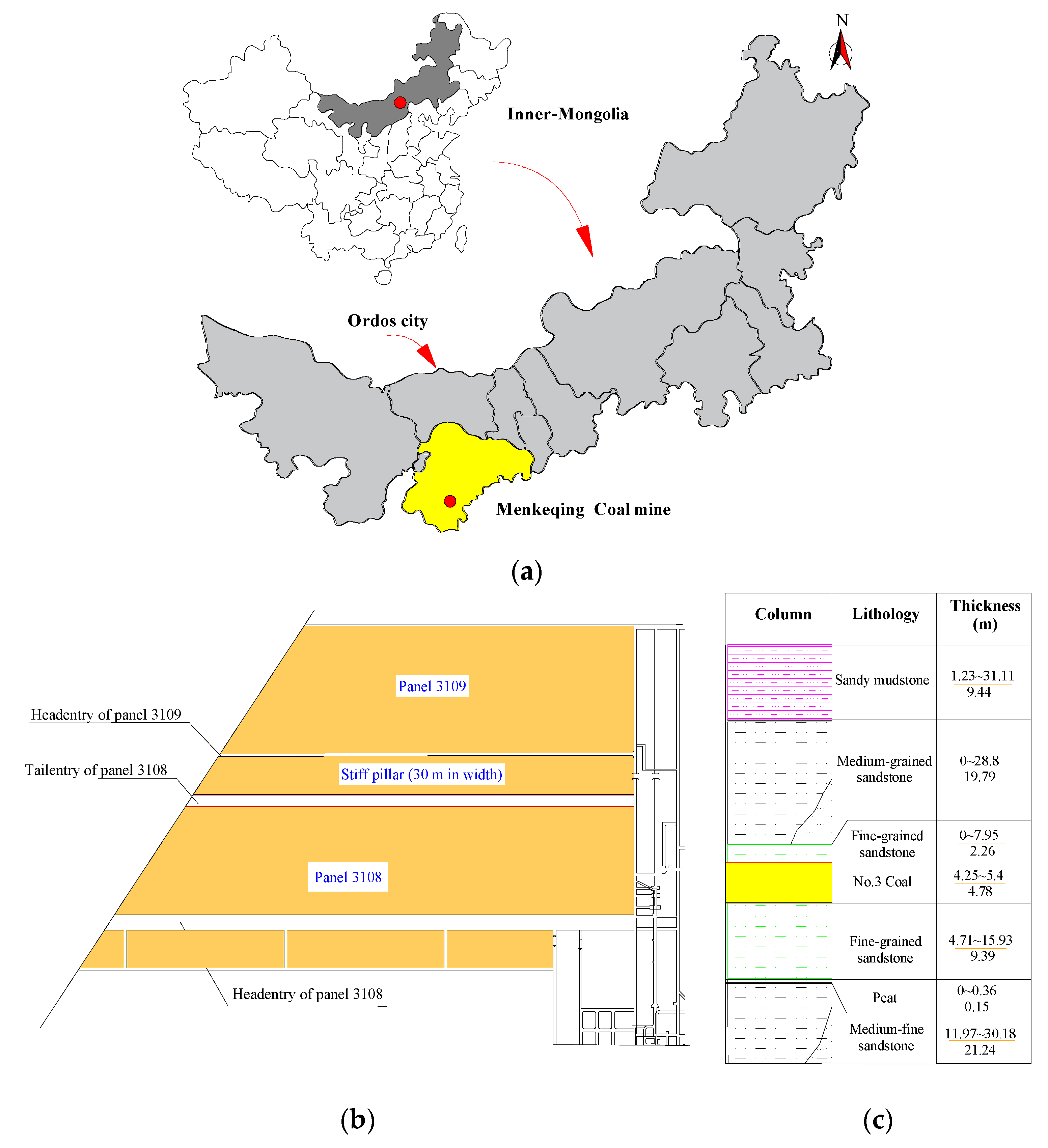
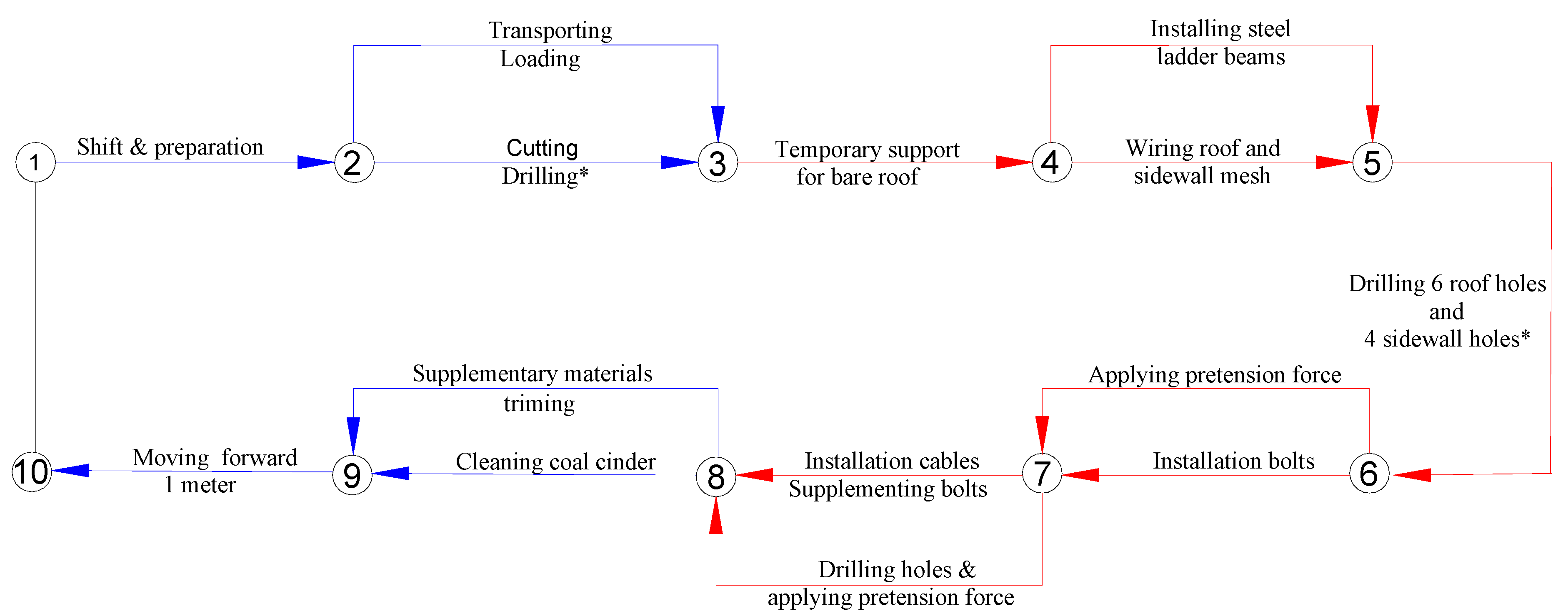
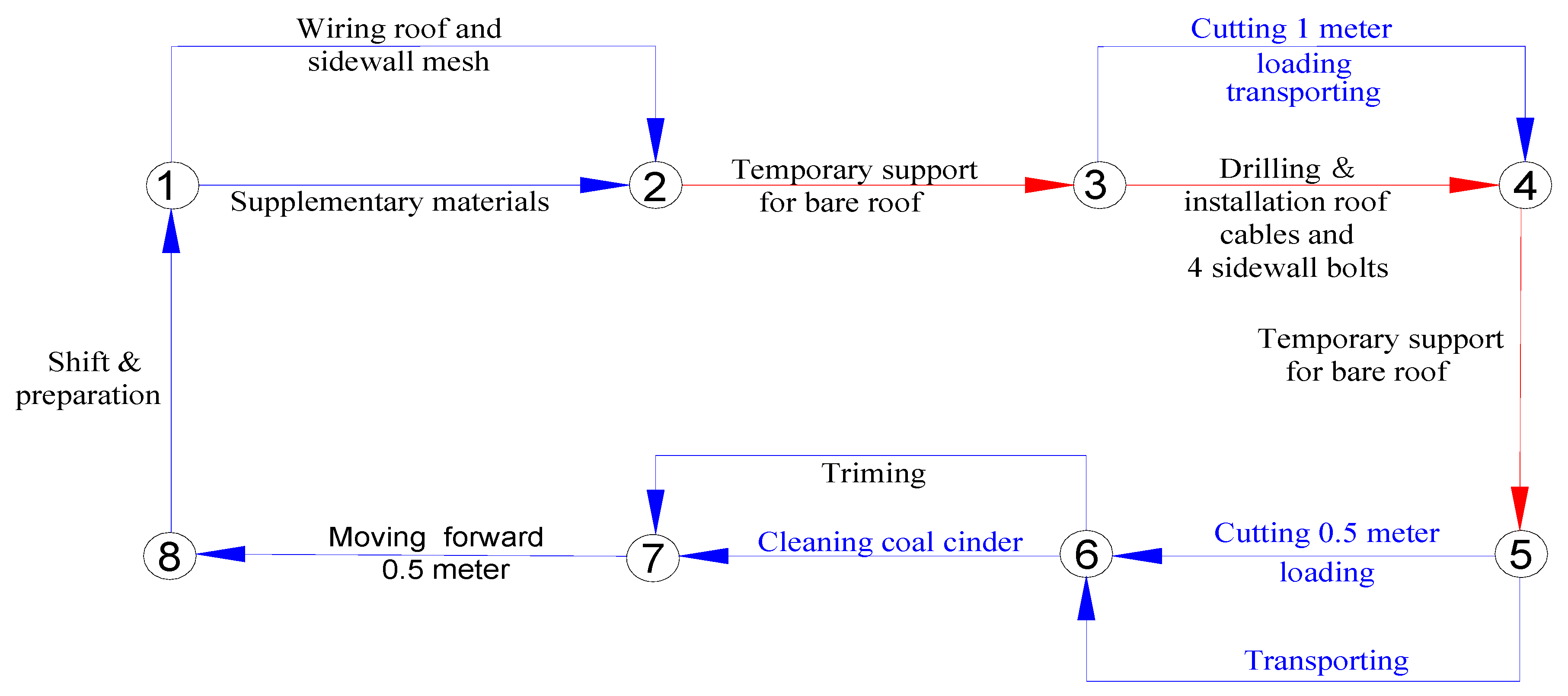
Time consumption of procedures within a unit cycle is a key factor that influences the speed of the whole process of roadway excavation. In general, a particular sequence and the links between each excavation procedure in a unit excavation cycle are relatively fixed in order to facilitate operation and proficiency. According to the on-site investigation in the tail entry of panel 3108, the originally used excavation process of BMRET is shown in
Figure 4. The time consumption of each procedure was tracked and monitored during the excavation process, as shown in
Table 3.
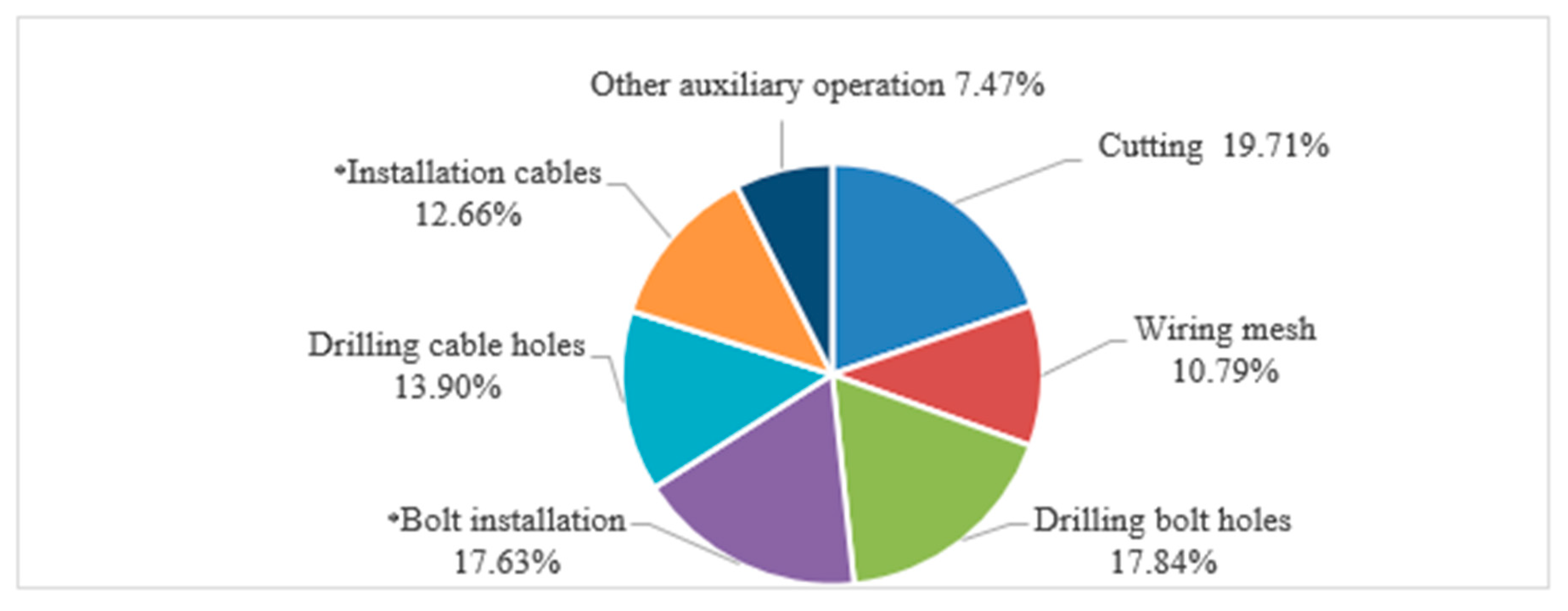
Based on the above data, the average time consumption of a unit excavation cycle (cutting 1 m forward) is 48.2 min, including 16 different procedures. In fact, in the process of excavation, cutting is the first step, and most of the time is dedicated to procedures related to support installation for the stability of the surrounding rock. In detail, the cutting time is 9.5 min, accounting for 19.71%. In contrast, the time used for supporting is 35.6 min, accounting for 73.86%. In order to specify the main time-consuming procedures in a unit excavation cycle, the procedures that took more than 5 min were analyzed, which include coal cutting, overlapping steel mesh, bolt drilling and installation, and cable drilling and installation. The time proportion of each procedure in a single cycle is shown in
Figure 5.
It can be seen that, in the whole excavation cycle, the time consumption of six procedures accounts for more than 92.53% of the whole time. Except for cutting, the remaining five procedures are all related to the roadway supporting procedures, which means the cutting capacity of the bolter miner is idle for 80.29% of the working time. Consequently, the supporting system is the main factor restricting the excavation speed, and optimizing the support scheme and reducing the time consumption of supporting are effective strategies for achieving rapid excavation.
The detailed procedures for installing the bolts and cables highly constrain the support speed. The main support procedures in a unit excavation cycle included drilling and installing, on average, 17 rock bolts and 0.67 cable bolts and wiring a steel mesh and a steel ladder. Thus, there exists a serious imbalance between supporting requirement and the supporting capacity of the bolter miner. However, due to the existence of parallel operation, a unit excavation cycle saves 15.1 min. It is suggested that optimizing and coordinating procedures to realize simultaneous operation is an effective way to achieve rapid excavation. Actually, parallel operation procedures, especially the more time-consuming procedures, are still few in the current excavation process because of the uncoordinated capabilities of current BMRET between cutting and supporting. Thus, the support procedures and parallel operation of BMRET need to be highly valued and studied.
3.2. New Proposed Evaluation Indicators
It is necessary to propose scientific indicators for quantitative evaluation of excavation speed and efficiency. From analyzing the current widely used speed evaluation indicators in underground roadway, there is a shortage of accurate indicators for rapid excavation evaluation, especially for the causal relationship between roadway support procedures and driving speed. Common indicators to evaluate the excavation speed mainly include the speed (including day speed and month speed), distance of excavation cycle, and worker efficiency [
11,
23].
The aforementioned indicators are mainly suitable for the evaluation of overall excavation technology from a macro perspective, which easily leads to superficial evaluation of the excavation speed. It is difficult to interpret the intrinsic relationship between the excavation speed and each procedure during the roadway excavation. Thus, new evaluation indicators are necessary for the organization of the working procedures along with quantitative methods for evaluating support efficiency in the excavation process. This paper proposes and defines two new indicators to scientifically quantify the excavation speed and the relationship between the main influencing factors for BMRET rapid excavation.
(1) Parallel operation index ()
The concept of parallel operation index is proposed to evaluate the degree of collaborative operation of each excavation cycle. The parallel operation index,
, is defined as the ratio of the saved time by the parallel operation procedures to the sum of the total cycle time in a single excavation cycle:
where
is the time saved by the parallel operation and
is the sum of actual time consumption in the whole unit excavation cycle.
Parallel operation index is an indicator used to quantify the effect of parallel operation. A high value of this index indicates that many procedures are being done at the same time and that there is a high efficiency of time utilization in the unit excavation cycle. This new indicator is a simple way to quantify the procedures’ organizational efficiency.
(2) Unit drilling-hole index ()
The workload of rock bolts and cable installation is obviously associated with roadway excavation speed, but the relationship between them has not yet been quantified. In order to evaluate the influence of the installation density of bolts and cables on the excavation speed, the concept of unit drilling-hole index,
, is suggested, which refers to the average length of holes needed to drill for every meter of the roadway:
where
is the total length of boreholes drilled for rock bolts and cables in a unit cycle and
is the length of a unit excavation cycle.
The bolt–cable combined supporting system exerts the function of strengthening rock mass by drilling holes in the rock mass. Thus, the length of the drilling can accurately represent the number of rock bolts and cables installed and also directly reflect the support density and time consumption of the support schemes. The unit drilling-hole index not only reflects the efficiency under different supporting schemes but also establishes the connection between supporting workload and excavation speed. Thus, the unit drilling-hole index is an effective parameter to evaluate the efficiency and speed of different supporting schemes. According to the definition, the unit drilling-hole index of the conventional bolt and cable combined support system was derived as follows.
where
is the length of the drilling hole for a roof bolt;
is the number of roof bolts;
is the length of the drilling hole for a roof cable;
is the number of roof cables;
is the length of the drilling hole for a bolt of one sidewall;
is the number of bolts for one sidewall;
is the length of the drilling hole for a sidewall cable;
is the number of cables for one sidewall;
is the length of the drilling hole of a bolt for the other sidewall;
is the number of bolts for the other sidewall;
is the length of the drilling hole for a cable of the other sidewall;
is the number of cables for the other sidewall; and
= 1 m.
4. New Support Scheme Design and Engineering Practice
4.1. New Support Design
A new roadway support system is proposed based on the features of the BMRET. It is known that a large number of support schemes have been put forward for deep roadway conditions, including yieldable steel arch support in Germany, a combined support scheme of bolts and cables in China, and various cable and bolt trusses with high pretension in America [
3,
4,
9,
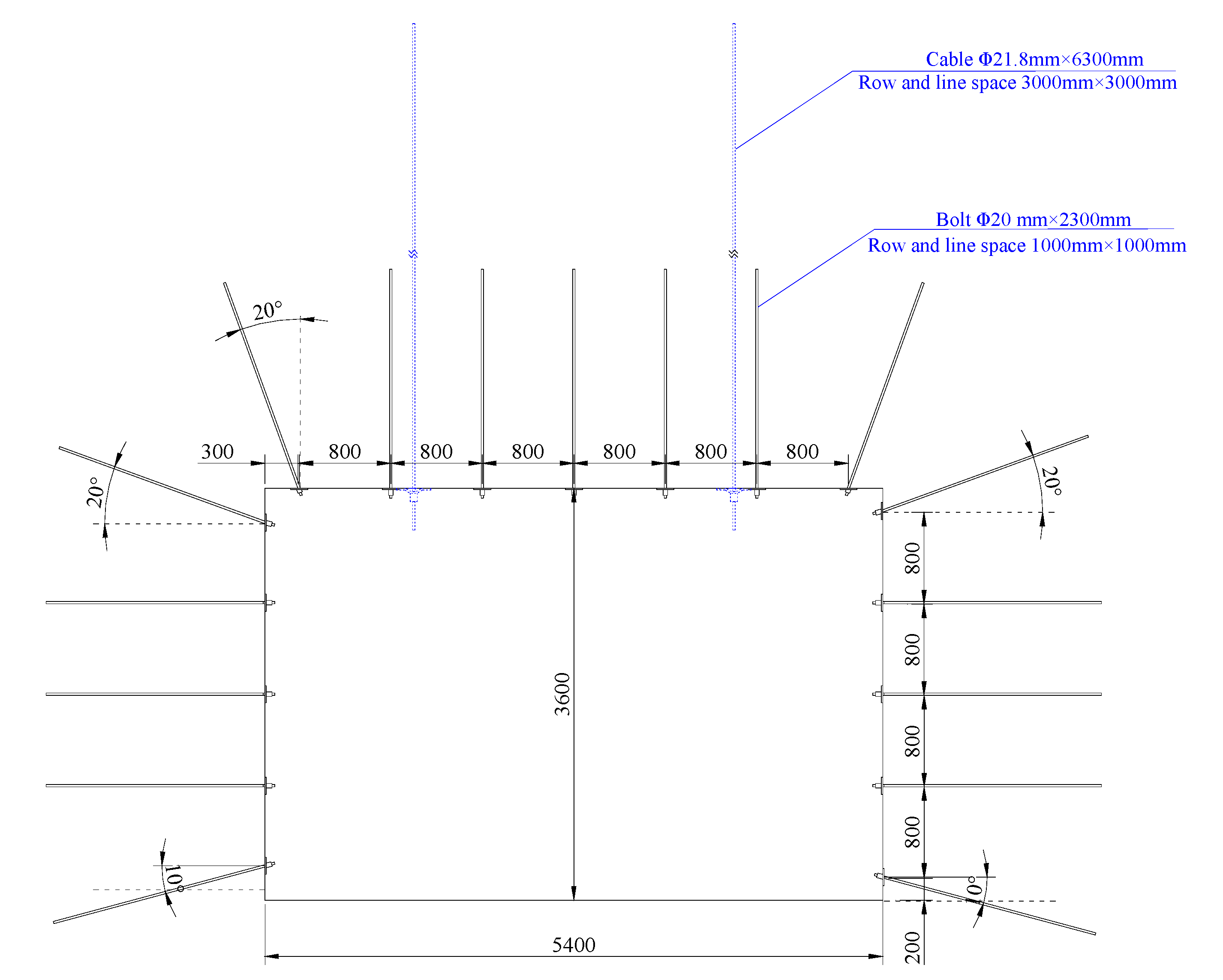
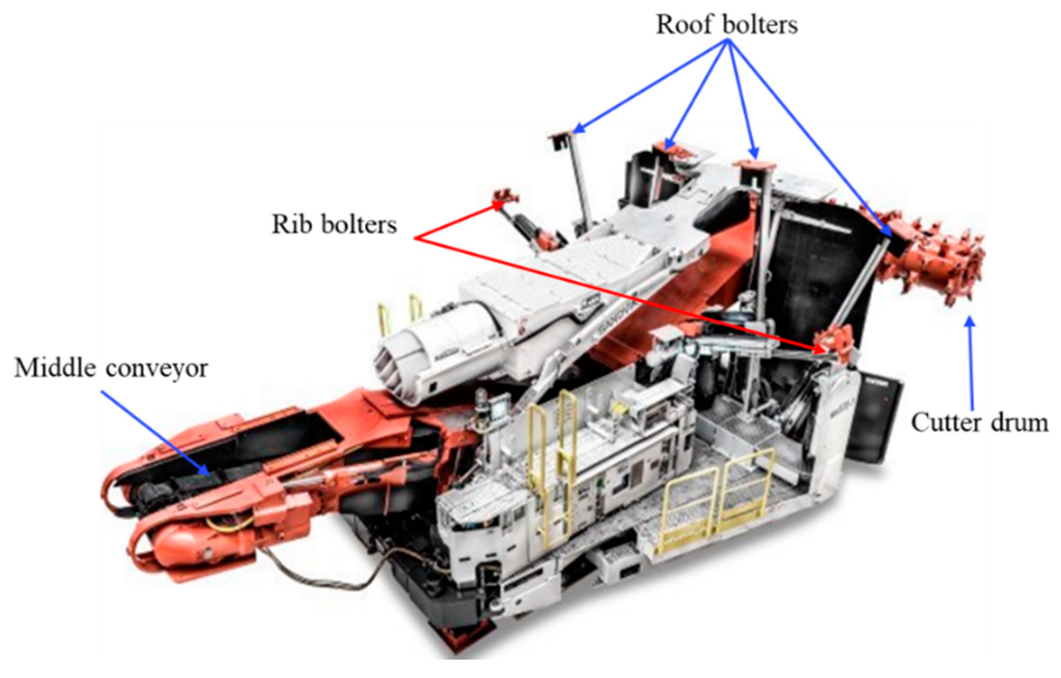
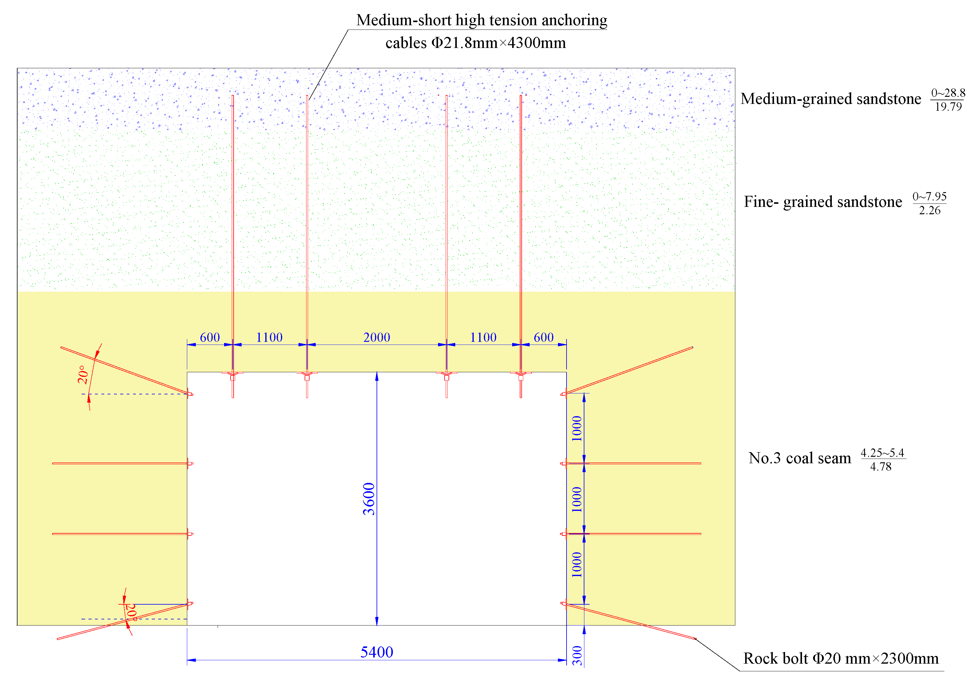
24]. However, these schemes lack consideration of the time-sensitivity of support procedures, performance of the key equipment, and coordination of the integral excavation system. The mainstream bolter miners in the market and mine sites were investigated, including Sandvik Mining and Construction Co., Ltd., Joy Mining Machinery Co., Ltd., Dosco Co., Ltd, and other companies. Based on the above background, and fully considering the time consumption of each procedure in a unit excavation cycle, a time-based and rapid support scheme is proposed and applied with medium–short high prestressed cables. The scheme of the new support system is shown in
Figure 6.
The key features of this new optimal support scheme are shown in the following:
(1) Simple and efficient roof support scheme.
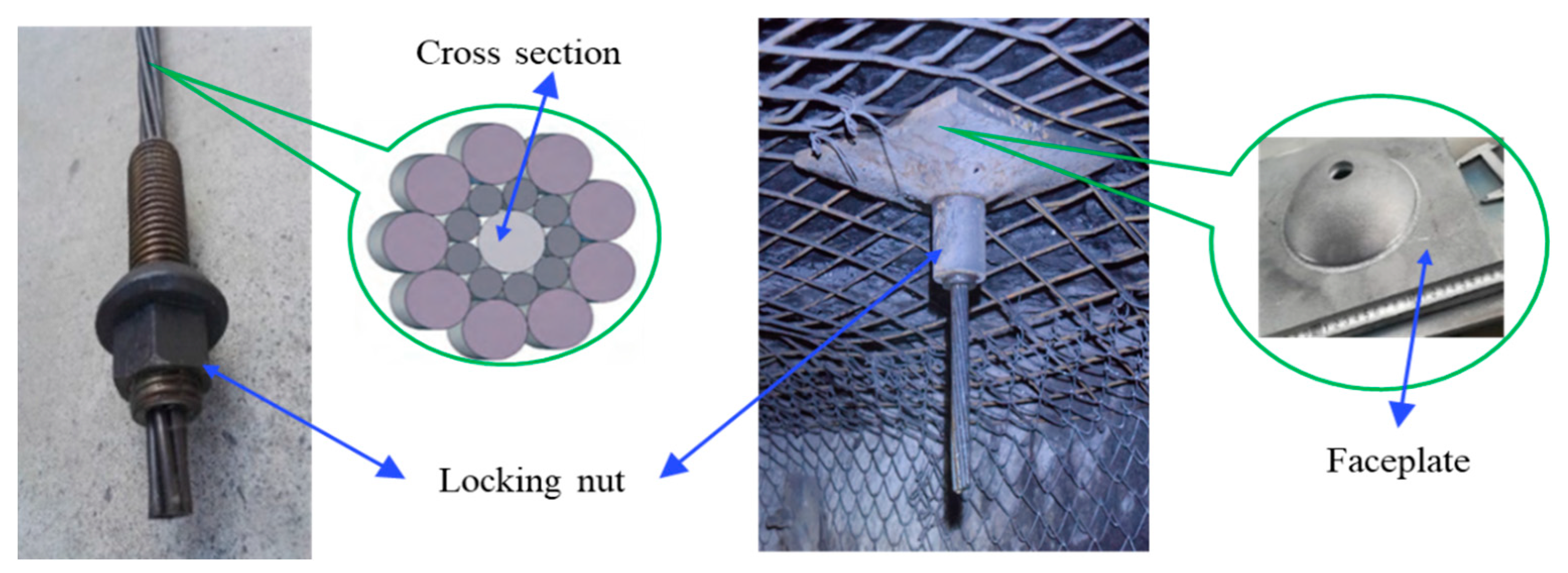
The roof of the entry is controlled and strengthened by four medium–short high prestressed cables matched with large-sized pallets (see
Figure 7).
The number of medium–short cables is consistent with the number of roof bolter rigs. The purpose of this design is to try to balance the time consumption of cutting and supporting and to try to realize the parallel operation of cutting and supporting. In addition, the rock bolts and other steel ladders for roof support are all eliminated, which greatly simplifies the supporting procedures and reduces the time consumption of roof supporting. The medium–short high prestressed cable is made of 19 high strength steel stands with a diameter of 21.8 mm and a broken load of 600 kN. The length of this cable is required to be 4~6 m; in this way it can be fully tensioned and effectively stretched, so that the roof convergence can be effectively restrained. Compared with the traditional cable, its strength and elongation are increased by 100%, and it not only has the characteristics of a cable but also exerts the function of a rock bolt. The large-sized pallets are required to be greater than 0.09 m2 in order to effectively diffuse the pretension of an anchor cable to the roof rock.
(2) High pretension force system.
The applied pretension force for each medium–short high prestressed cable is over 200 kN; therefore, the free end of the high-tension cable is in a state of elastic stretch, which generates a high pressure on the roof to restrain the settlement. Additionally, the pretension force for bolts is required to be up to 80 kN, both for roof and rib bolts. High pretension force is an effective way to improve the bolting effectiveness.
(3) Immediate support.
Since the cutting and supporting procedures are carried out simultaneously, this new support system realizes the possibility of immediate support. The free deformation time of the newly excavated roadway section is controlled within a short time (within 10 min), which can inhibit the early subsidence of the roof and restore the rock mass to the equilibrium state as soon as possible. The rib support in the new system is designed dynamically according to the excavation speed of the roadway, leaving space for the adjustment and release of surrounding rock stress and ensuring safety as well as excavation speed.
4.2. New BMRET and Field Application
After adopting this new support system, the optimal BMRET was named the new BMRET. In order to validate and further interpret this new excavation system, the reliability and effects were verified by a case study. The time consumption of the procedures of the excavation cycle and distance were monitored. Finally, the evaluation was carried out with new indicators, and the results were compared with the original plan. Procedures in a unit excavation cycle have been simplified under the new support system due to the balanced cutting and supporting capacities. Based on the onsite monitoring, the excavation process of this new BMRET is shown as
Figure 8.
Compared with the original system, the number of parallel procedures was obviously increased, which can exert the functions of the bolter miner. In the course of site excavation, the time consumption of each excavation procedure was carefully monitored by tracking two working shifts for over one month (see
Table 4). With a cycle distance of 1500 mm, the average time consumption of a unit excavation cycle is 22.7 min. Compared to the original scheme, the time saved by this new BMRET is 24 min from the perspective of cycle time consumption.
Under this new technology, the three-shift working system was adopted, with two shifts for excavation and one for maintenance, the same as the original system. The distance achievable with this new system within 20 days is shown in
Table 5.
The average excavation speed is 36.15 m/day and 1080 m/month under the new BMRET. Compared with the original system, the excavation speed of this new technology increases by 99.72%.
(1) The parallel operation index of new BMRET
The parallel operation index was calculated in order to assess the organizational efficiency and time utilization efficiency of the new BMRET. According to the data of the on-site time monitoring, 23.1 min is saved, and actual time consumption in a total excavation cycle is 22.7 min. Thus, the final parallel operation index is:
Under the new excavation technology, the parallel operation index reaches 101.76%. This means that the time saved by parallel operation exceeds the real-time consumption of a unit excavation cycle, and the efficiency of time utilization is improved 69% compared with the original system.
(2) Unit drilling-hole index
The essence of the new support is one type of rock bolt-cable combined support system. Accordingly, the unit drilling-hole index can effectively evaluate the support efficiency and density of this new system. Within a distance of 1500 mm, four high strength medium–short cables were installed on the roof, and eight rock bolts were installed in two sidewalls. Hence, the unit drilling-hole index of the new system can be calculated by Equations (2) and (3):
As a result, the unit drilling-hole index of the new BMRET is 22.40, which means the length needed to drill holes for excavation 1 m forward is 22.40 m. Compared to the original system, the length of the drilling holes has been reduced by 19 m and 45.89% in the new BMRET for every 1 m distance. Furthermore, the time consumption for the support procedures decreases significantly due to the workload of drilling and installation being reduced greatly. Thereby, the efficiency of the time utilization of the entire system has obviously improved.
4.3. Results and Discussion
The mechanisms associated with the new support scheme are elaborated by means of numerical simulation from another publication. The reliability of this new supporting system has been confirmed in similar case studies [
17,
23]. In this study, the support effectiveness of the new support scheme was analyzed by some accurate field measurement methods. The roadway convergence, the axial force of the high strength medium–short cables, and fracture development in the roof of the roadway under the new BMRET were monitored. Three kinds of monitoring equipment were mainly used at this site, namely, a hand-held laser range finder for the surface displacement of the roadway, borehole scanners for fracture development in the surrounding rock, and digital dynamometers to monitor the axial force of the cable.
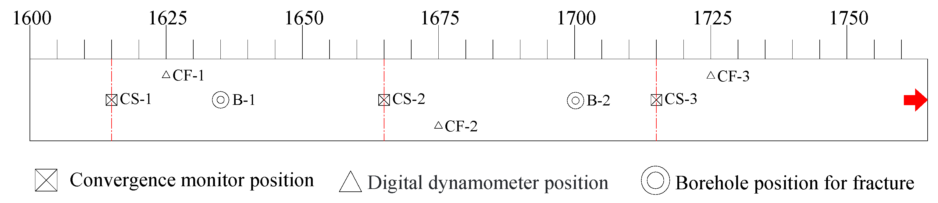
Figure 9 shows the monitoring and schemes in the field for a distance of 150 m (from 1600 to 1750 m in roadway 3108).
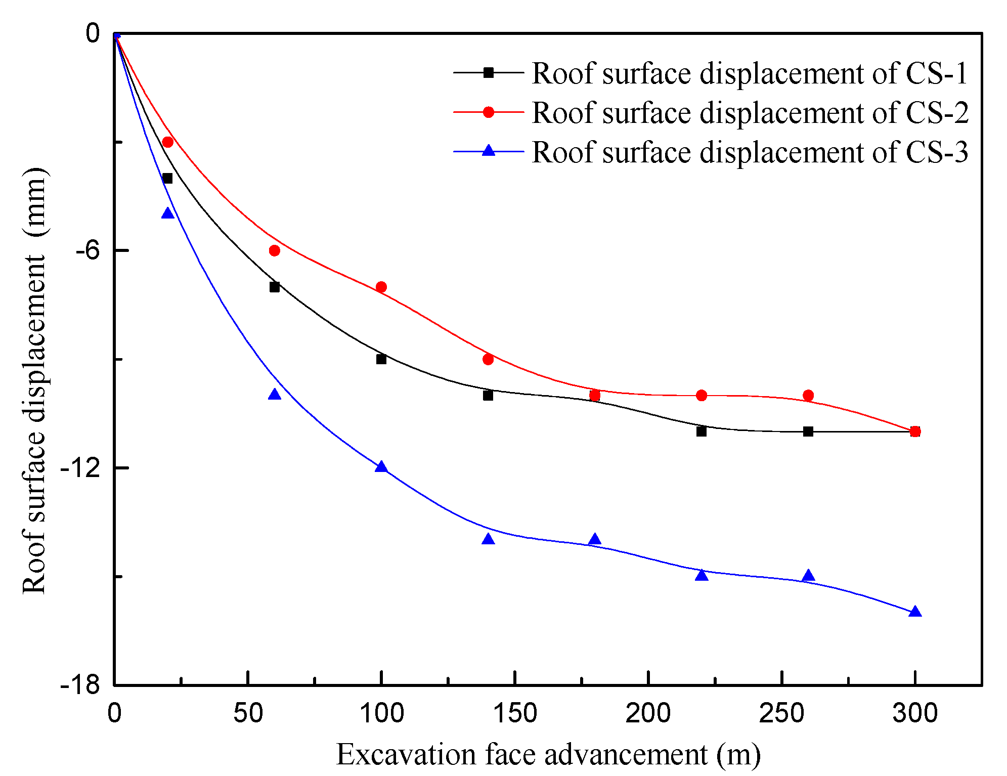
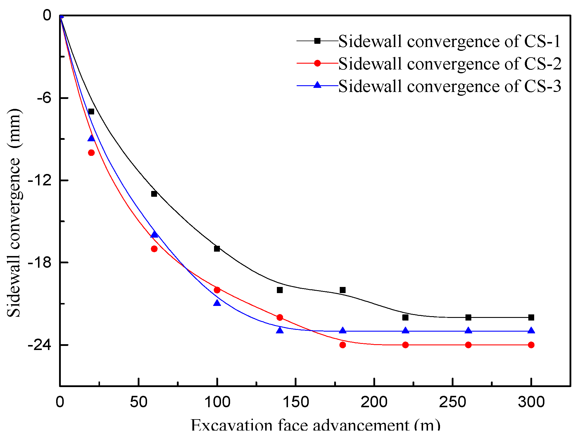
The convergence of the roadway can reflect the relative displacement and stability of the inner part of the rock mass. The adaptability of support schemes to the rock mass can be effectively evaluated from this perspective. The intersection point method was applied to measure the convergence of the roadway section, including roof subsidence and two-side convergence, and three monitoring sites were chosen as observation sections to record the variation of roadway convergence after the implementation of the new supporting scheme. The results are shown in
Figure 10 and
Figure 11.
According to the monitoring data, the maximum displacement of the roof is 17 mm, and the average subsidence is 13.7 mm. The maximum convergence of sidewalls is 24 mm with an average value of 23 mm. This demonstrates that the whole convergence of the roadway is quite low.
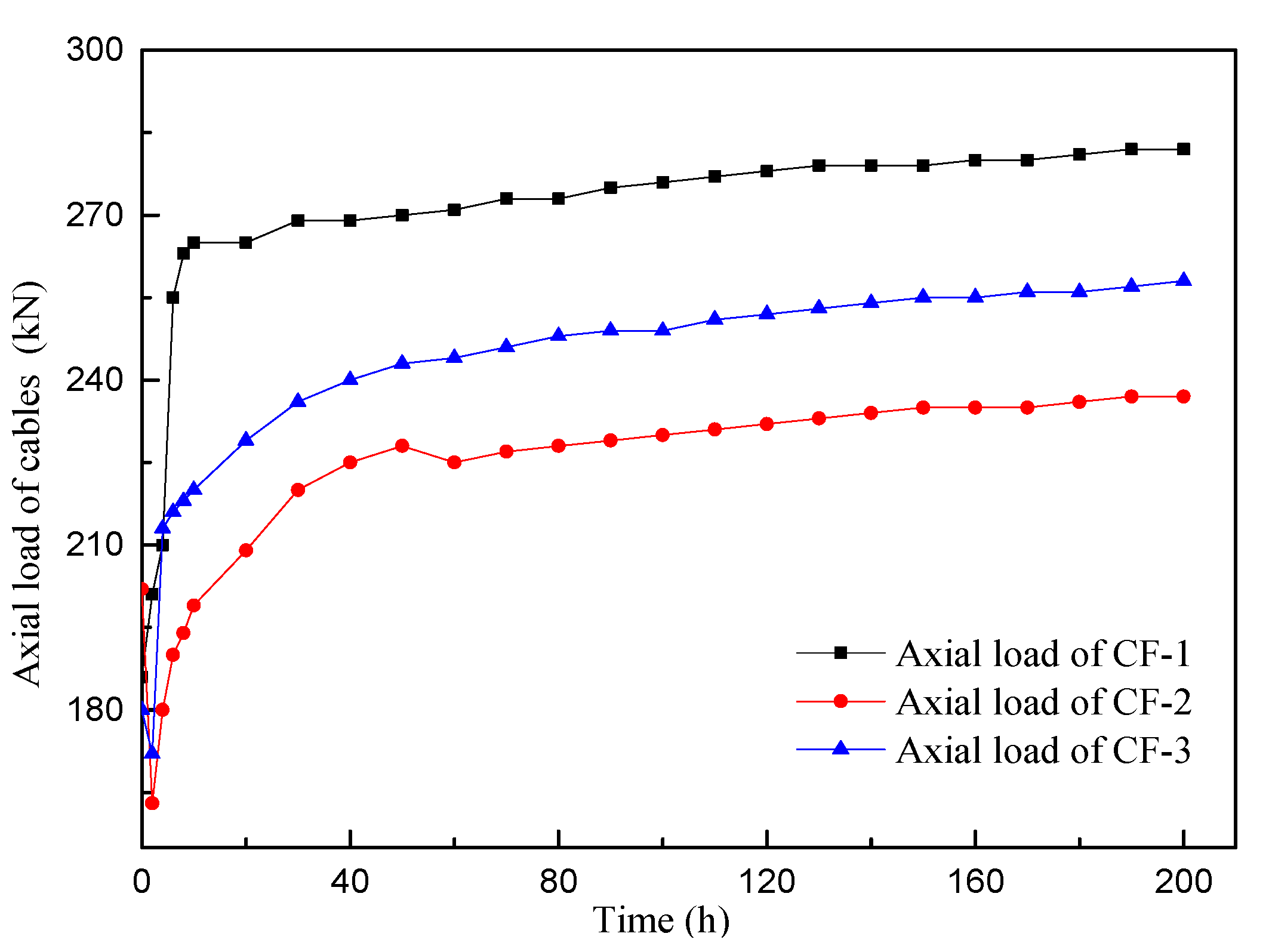
The axial load of the prestressed cables was monitored to evaluate their working state. In the field test, digital dynamometers were used as sensors to monitor the axial force. After cable installation, the axial load was measured over time. Monitoring results are as shown in
Figure 12.
From the monitoring results, the axial load of the cable is up to 220 kN after stabilization. The axial load of the medium–short high prestressed cable first increases after installation, then gradually becomes stable. To be specific, within 10 h after installation, the axial load of the cable changes drastically, then growth tends to be moderate, and it becomes stable after 80 h with a value up to 220 kN. The final state of the cable is tense due to it being subjected to a higher workload, which is beneficial in maintaining the stability of the surrounding rock. Additionally, the high load bearing state is also conductive to exerting the supporting performance of the cable.
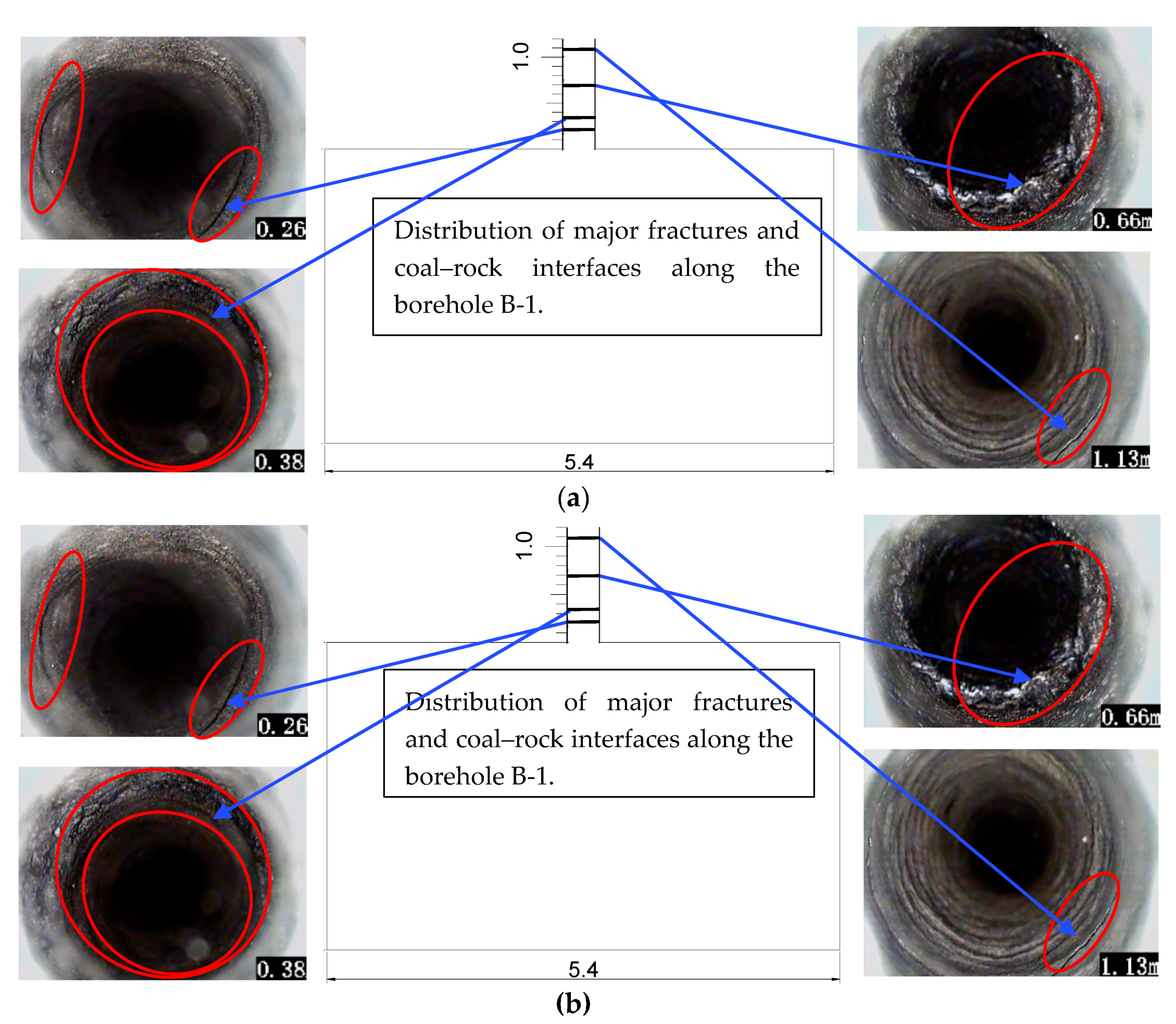
Borehole image monitoring of the roof fracture development was carried out to confirm the rock mass condition. By monitoring the rock mass discontinuity and internal fracture development, the reliability of the support scheme can also be effectively evaluated. In this research, the surrounding rock was monitored by a ZKXG30 borehole scanner, which can show the fracture distribution and development trend within 10 m of rock mass by an endoscope head. The fracture images are shown in
Figure 13.
According to the results of borehole image monitoring, the separation and fracture development in the rock mass is in the range of 1.27 m from the roof surface. Fractures were only observed in the shallow depth and coal–rock interface of the roadway roof. The largest fracture opening is within 2 mm. There is no visible fracture development in the rock mass above 1.27 m. Therefore, based on the roadway monitoring results, the use status and effect of the new BMRET, and through the scientific comparison of the two systems before and after, it is concluded that the new technology has a good overall controlling effect on the surrounding rock of the entry.


