Article

The Impact of Hybrid Energy Storage System on the Battery Cycle Life of Replaceable Battery Electric Vehicle

1
School of Mechanical Engineering, Anhui Science and Technology University, Chuzhou 233100, China
2
School of Mechanical Engineering, University of Science and Technology Beijing, Beijing 100083, China
*
Author to whom correspondence should be addressed.
World Electr. Veh. J. 2023, 14(9), 248; https://doi.org/10.3390/wevj14090248
Submission received: 13 August 2023 / Revised: 26 August 2023 / Accepted: 2 September 2023 / Published: 5 September 2023
(This article belongs to the Topic Electric Vehicles Energy Management)

Abstract

:
Compared with batteries, ultracapacitors have higher specific power and longer cycle life. They can act as power buffers to absorb peak power during charging and discharging, playing a role in peak shaving and valley filling, thereby extending the cycle life of the battery. In this article, a replaceable battery electric coupe SUV equipped with a lithium iron phosphate (LiFePO4) power battery is taken as the research object, and a vehicle dynamics simulation model is established on the MATLAB/Simulink platform. Parameter matching and control optimization for a hybrid energy storage system (HESS) are conducted. Through a proven semiempirical cycle model of the LiFePO4 power battery, the operating cycle life model is derived and used to estimate the battery cycle life. World Light Vehicle Test Cycle (WLTC) simulation results show that the HESS with 308 ultracapacitors can extend the cycle life of the LiFePO4 power battery by 34.24%, thus significantly reducing the operation cost of the battery replacement station.

1. Introduction

Replaceable battery electric vehicles can not only be charged using the power grid one but can also directly replace the fully discharged power battery in the vehicle with a fully charged power battery. Recently, some car companies have launched replaceable battery electric vehicles and provided battery replacement services to solve the problems of high purchase cost and long charging time of electric vehicle power batteries. This allows consumers to use batteries on a rental basis without purchasing them when purchasing replaceable battery electric vehicles. When the battery is low, consumers can go to the battery replacement station to receive a fully charged battery. The entire battery replacement process takes 3–5 min, and the lengthy charging task is entrusted to the battery replacement station. This enables users to have the same convenient energy replenishment experience as for traditional fuel-powered vehicles when using battery electric vehicles, enhancing the competitiveness of replaceable battery electric vehicles. However, compared to charging stations, the operating cost of battery replacement stations is clearly higher. The battery replacement station requires a complete battery replacement system and a certain amount of power batteries, so the operation and maintenance costs are higher than those of charging stations. Due to the high cost of power batteries, it is of great economic significance for battery replacement stations to adopt measures such as optimizing charging and battery balancing to extend battery life. One feasible technology and method to extend the cycle life of batteries is to use batteries and ultracapacitors to form a hybrid energy storage system [1,2,3,4]. By optimizing the distribution of power between batteries and ultracapacitors through control strategies, the high specific power characteristics of ultracapacitors are fully utilized to perform peak shaving and valley filling on batteries, recover regenerative braking energy, and improve battery usage and extend battery cycle life.
Wu et al. used a lithium iron phosphate (LiFePO4) battery and ultracapacitor to form a hybrid energy storage system, which improves the efficiency of the vehicle energy storage system [5]. Wang et al. used the dynamic programming (DP) algorithm to obtain the optimal energy allocation strategy, reducing the peak current of the battery and improving the energy efficiency of the energy system [6]. Zhang et al. used model predictive control (MPC) to obtain operating conditions data and optimize HESS energy allocation in the prediction domain through partial historical data and prediction models [7]. Alaoui et al. optimized and normalized the known offline energy consumption data features and trained artificial neural networks (ANNs) to obtain allocation results that maximize HESS efficiency [8]. The above control optimization relies on known offline operating conditions data and accurate prediction models, and the algorithm is complex and difficult to use online in real vehicles. Therefore, it is also known as an offline control strategy.
In [9,10], Song and Zhang et al. designed the fuzzy logical control (FLC) strategy for HESS electric vehicles, which improved the power and economy of EVs. FLC does not rely on precise mathematical models but on the knowledge and experience of experts. In [11,12,13], low pass filtering (LPF) was used to separate the high-frequency and low-frequency parts from the energy consumption curve of the vehicle’s operating conditions and the HESS was controlled and optimized by the battery and ultracapacitor outputs, respectively. In addition, rule-based controllers also include load tracking control and threshold strategy. The above method can quickly implement a control strategy for HESS energy allocation online, hence it is also known as an online control strategy.
Compared to the research on HESS energy allocation strategies, there is little research on HESS parameter matching. Sadoun et al. estimated the optimal mixing degree of HESSs based on the HESS energy allocation strategy and derived the matching parameters of HESSs [14]. Zhang et al. established a HESS parameter-matching model to analyze and match its parameters in order to achieve optimized battery life for energy allocation strategy [15]. In [16,17], different parameter-matching and control strategies were used for a HESS to study the impact on battery cycle life and try to extend the cycle life of the battery. Liu et al. proposed a HESS parameter-matching method that can meet the performance indicators of electric vehicles in terms of power and energy and achieve optimized parameter matching by reducing weight and cost [18].
In addition to battery electric vehicles, a HESS has also been applied in hybrid electric vehicles and fuel cell vehicles to improve and enhance energy systems. In [19,20,21], the application of a HESS to hybrid electric vehicles improved vehicle power and economic performance. Djouahi et al. applied a HESS to fuel cell electric vehicles, replacing a single battery power buffer and reducing fuel consumption by simultaneously optimizing the component size and power management of the HESS [22].
In summary, for HESSs, energy distribution strategies and parameter matching are key to leveraging the high energy density and power density characteristics of batteries and ultracapacitors and extending the lifespan of lithium-ion batteries [23]. This article takes a replaceable battery electric coupe SUV equipped with a LiFePO4 battery as the research object. Firstly, we establish a vehicle dynamics simulation model on the MATLAB/Simulink platform, using a rule-based controller, and optimize the HESS control strategy parameters while optimizing its matching parameters. In order to calculate the battery cycle life more accurately, a proven semiempirical life model of a LiFePO4 battery was used to derive its driving cycle life model, which was then used to estimate the battery cycle life. In order to make the simulation results closer to the actual situation, the World Light Vehicle Test Cycle (WLTC) driving cycle, which is widely considered to be closer to the actual situation, was used to analyze and study the capacity degradation of LiFePO4 batteries in the single battery energy system and the hybrid energy storage system.

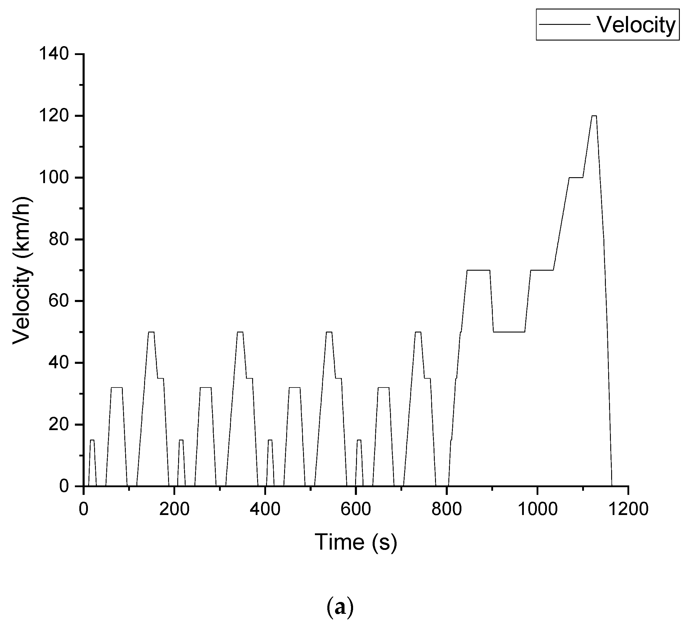
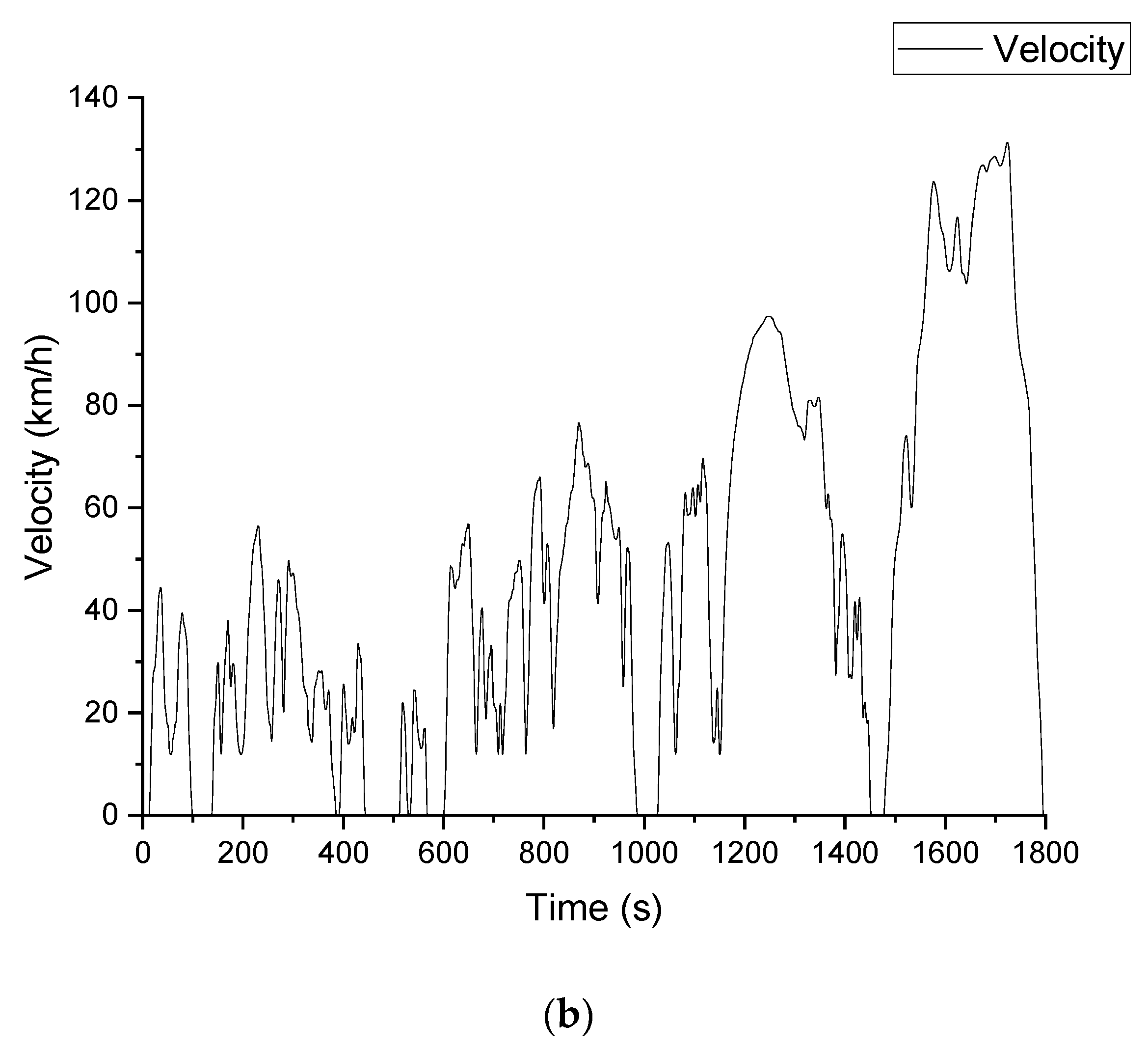
2. Vehicle Parameters and Models

The model studied in this paper is a Chinese-made four-wheel drive battery replaceable electric coupe SUV, and the main parameters are shown in Table 1. The vehicle is equipped with a 71.72 kW·h LiFePO4 battery pack and two 130 kW drive motors. The New European Driving Cycle (NEDC, Figure 1a) provides a comprehensive driving range of the vehicle of 400 km. However, according to the data from a car enthusiast forum, the actual testing mileage is about 360 km. To make the simulation results closer to reality, the World Light Vehicle Test Cycle (WLTC, Figure 1b) driving cycle is adopted. Table 2 provides the NEDC and WLTC driving cycle test parameters and data. It can be seen that the maximum speed, average speed, and maximum acceleration of the WLTC driving cycle are all higher than those of NEDC in terms of vehicle power demand indicators. The testing content of the NEDC standard includes five operating conditions, four urban cycles, and one suburban cycle. The testing content of the WLTC standard includes four types: low speed, medium speed, high speed, and ultra-high speed [24]. The NEDC testing standard was born in the 1980s and was last modified in 1997, which is relatively outdated. The WLTC driving cycle is the testing standard for global light vehicle testing standards, developed by the United Nations and born in 2017. Under the WLTC driving cycle simulation, the vehicle has a driving range of approximately 366 km, which is basically consistent with the car enthusiast forum.
The vehicle dynamics model is built on the MATLAB/Simulink platform (version R2021b) using the backward simulation method [25,26]. This model includes working condition files, vehicle modules, transmission modules, electric motor modules, and energy storage system modules. The model takes the driving cycle file as input, passing the vehicle speed, torque, and rotation speed or power demand from left to right. The specific modeling process refers to [27].This article will not elaborate on the modeling process in detail.

3. Driving Cycle Life Model of LiFePO4 Battery

To accurately estimate the impact of a hybrid energy storage system on battery cycle life, a reliable driving cycle life model of the LiFePO4 battery is essential. In this paper, the proven semiempirical constant current charging and discharging battery cycle life model is used to derive the LiFePO4 battery driving cycle life model.

3.1. Cycle Life Model of Constant Current Charge and Discharge for LiFePO4 Battery

Researchers have carried out a lot of research on the constant current charging life model of the LiFePO4 battery. Ref. [28] studied the constant current discharge cycle life of a 2.2 A·h cylindrical LiFePO4 battery and obtained the following formula:
Q l o s s = B × e x p E a R T × A h z
where Q l o s s is the percentage of capacity loss of the battery; B is the preexponential factor; E a is the activation energy; R = 8.314 J/ (mol·K) is the general gas constant; T = 298.15 K is the absolute temperature corresponding to 0 and T = 298.15 K to room temperature of 25 ; A h is A · h throughput:
A h = N × D O D × C b
where N is the number of discharges; D O D is the depth of discharge; C b is the battery capacity.
By curve fitting experimental data with fixed discharge rates of 0.5, 2, 6, and 10C, the B , E a , and z at each discharge rate were obtained, as shown in Table 3.
Through parameter fitting, the general formula for the cycle life of the LiFePO4 battery with a fixed discharge rate is as follows:
Q l o s s n = B n × e x p 31700 + 370.3 × n R T × A h z
where n is the multiple of 1C discharge rate, corresponding to different discharge rates of 0.5, 2, 6, and 10C; B n is 31,630, 21,681, 12,934, 15,512, respectively; z is 0.55.
The l n B n decreases with the increase in discharge rate n [16,29] and, as shown in Figure 2, is fitted as follows:
l n B n = 10.274 0.105 n

3.2. Cycle Life Model of LiFePO4 Battery under Driving Conditions

The working current of the battery is constantly changing, and the semiempirical formula obtained by fitting the experimental data of constant current charging and discharging life cannot accurately reflect the battery life under driving cycle conditions. Therefore, it is necessary to establish a battery life model under driving cycle conditions [29].

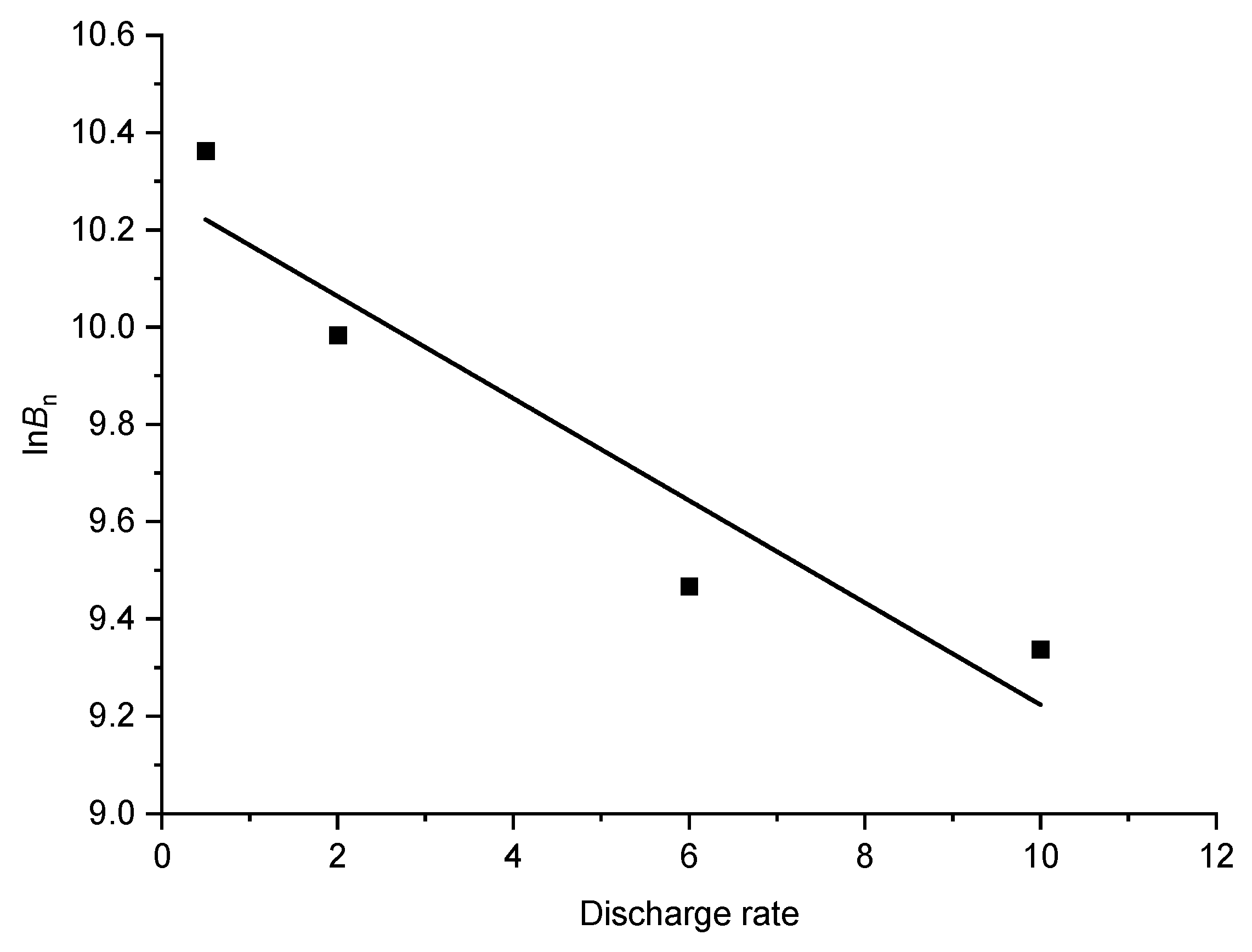
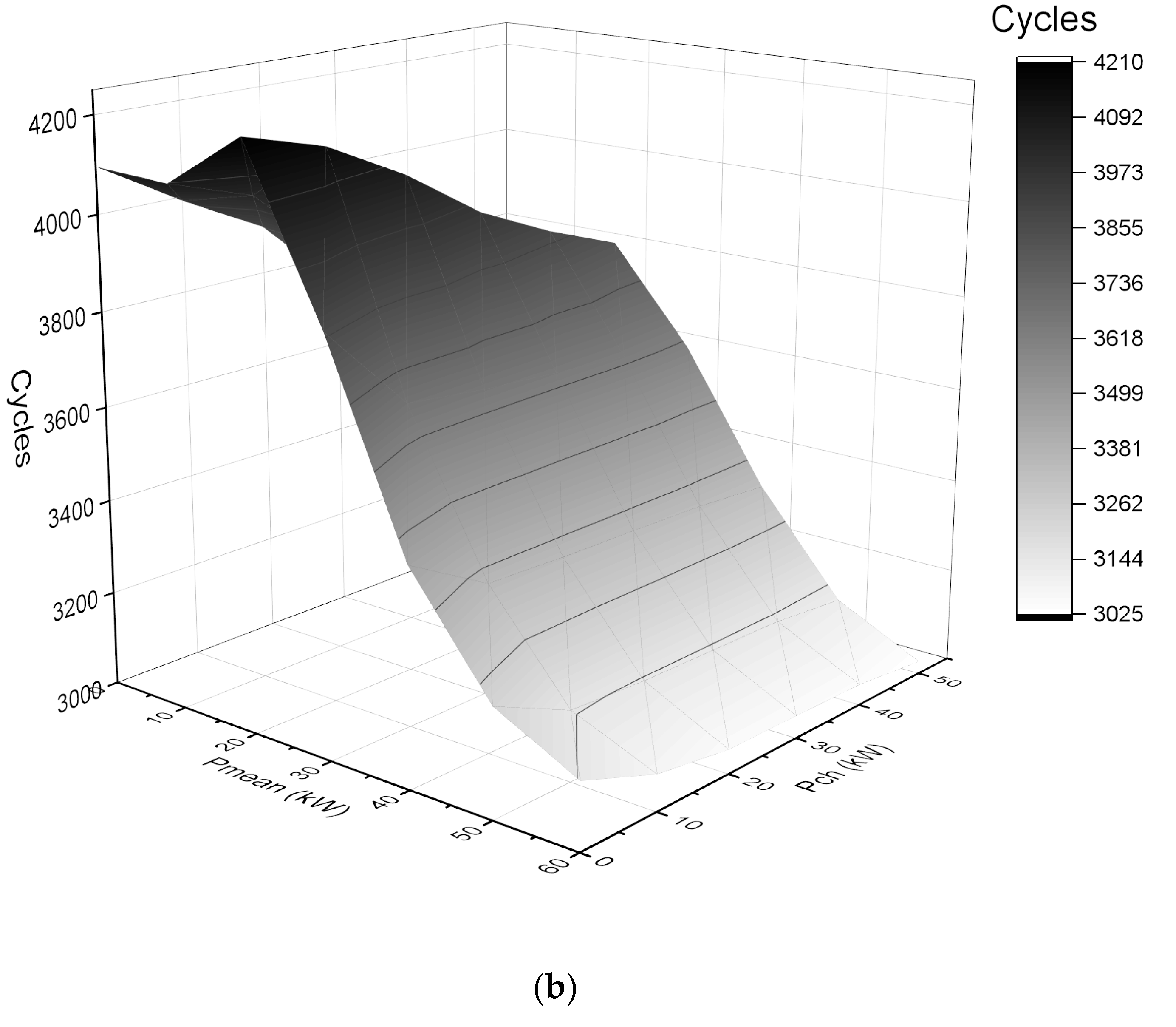
3.2.1. Equivalent Cumulative Ampere Hours Released at Different Discharge Rates under Equal Lifespan Conditions

By using the equivalent life condition, the cumulative ampere hours released at different discharge rates can be equivalent to the cumulative ampere hours released at a certain discharge rate. If A h 1 _ n is the amount of electricity released at nC discharge rate under equal lifespan conditions and A h n is equivalent to the ampere hours released at 1C discharge rate, then:
A h 1 _ n = B n B 1 × e x p 370.3 ( n 1 ) R T 0.55 × A h n
By introducing (5) into (3), the equivalent battery cycle life formula for nC discharge rate to 1C discharge rate can be obtained:
Q l o s s 1 _ n = B 1 × e x p 31329.7 R T × B n B 1 × e x p 370.3 ( n 1 ) R T 0.55 × A h n 0.55

3.2.2. Battery Driving Cycle Life Model

Dividing the driving cycle into t equal time intervals t , the discharge rate of the battery at time t is n t . The 1C discharge rate discharge current is recorded as I 1 . The discharge amount A h n t of the battery at time t is calculated using the ampere hour method:
A h n t = n t I 1 3600 × t
Bringing Formula (7) into Formula (6) obtains the equivalent battery cycle life at time t :
Q l o s s 1 _ n t = B 1 × e x p 31329.7 R T × B n t B 1 × e x p 370.3 ( n 1 ) R T 0.55 × n t I 1 3600 t 0.55
After a driving cycle at room temperature, the battery cycle life loss Q l o s s 1 is:
Q l o s s 1 = B 1 × e x p 31329.7 R T × 0 t B n t B 1 × e x p 370.3 ( n 1 ) R T 1.19 × n t I 1 3600 t 0.55
The loss of battery cycle life after m driving cycles is:
Q l o s s m = B 1 × e x p 31329.7 R T × m 0 t B n t B 1 × e x p 370.3 n 1 R T 1.19 × n t I 1 3600 t 0.55

4. Hybrid Energy Storage System Model

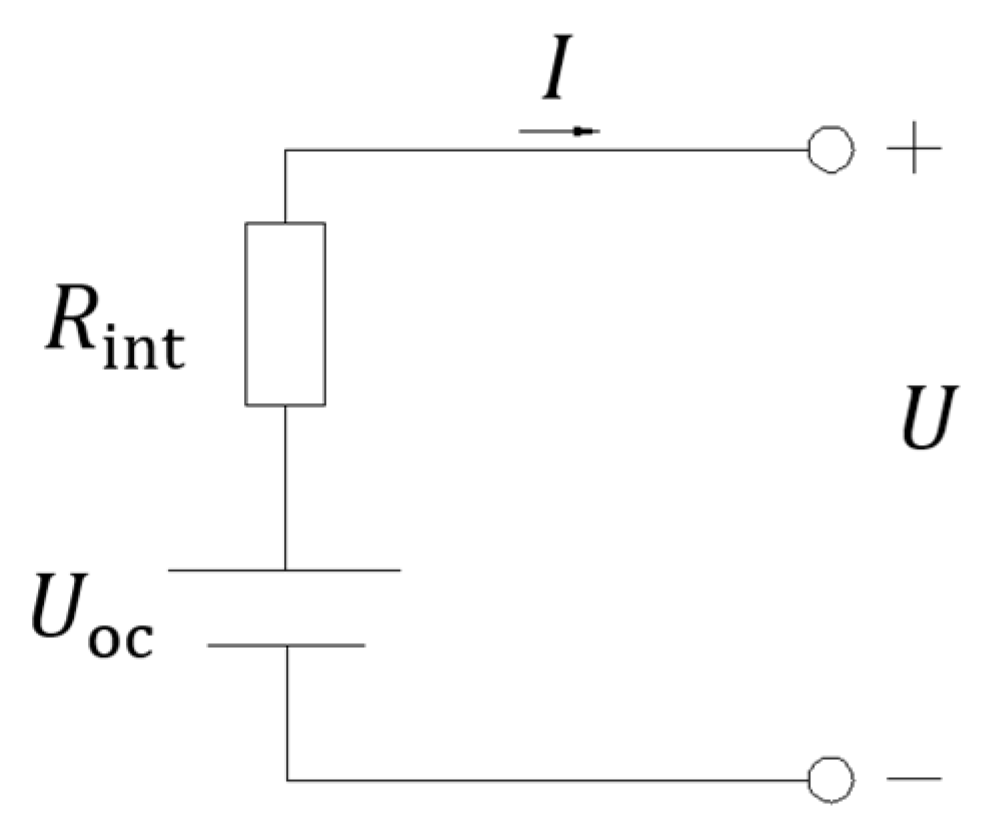
4.1. Parameters and Model of LiFePO4 Battery

The electric coupe SUV uses a LiFePO4 battery with a high energy density structure, which has higher battery efficiency and reliability. The rated voltage of the battery is 3.2 V, and the capacity is 135 A·h. The main technical parameters for constant current charging and discharging at room temperature are shown in Table 4.
Using the internal resistance model R i n t , as shown in Figure 3.
Battery terminal voltage U :
U = U o c I R i n t
Output power P b :
P b = U I
Bringing (11) into (12) to solve the bus current I:
I = U o c U o c 2 4 P b R i n t 2 R i n t
Discharge efficiency η b _ d :
η b _ d = U I U o c I = U o c I R i n t U o c
Charge efficiency η b _ c :
η b _ c = U o c I U I = U o c U o c + I R i n t
State of charge (SOC) consumption S O C b :
S O C b = I η c o u l 3600 C b Δ t
where U o c is the open circuit voltage of the battery, which is a function of SOC and can be obtained by looking it up in the table; R i n t is the equivalent resistance, which is a function of SOC and can be obtained by looking it up in the table; C b is the battery capacity.

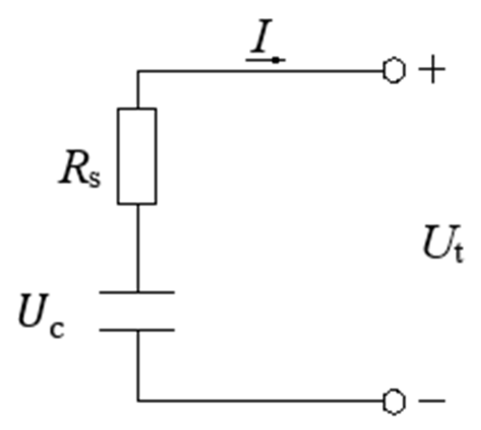
4.2. Parameters and Model of Ultracapacitor

Compared to batteries, ultracapacitors have a high specific power and can be quickly charged and discharged at high currents with an efficiency of over 95%. They can be reused 10 6 times (about 40 years). This article uses an ultracapacitor with a rated voltage of 2.7 V, and the main technical parameters are shown in Table 5. Figure 4 shows the equivalent model of the ultracapacitor.
Ultracapacitor terminal voltage U t :
U t = U c I R s
Output power P c :
P c = U c I
Bringing (17) into (18) solves the bus current I:
I = U c U c 2 4 P c R s 2 R s
Discharge efficiency η c _ d :
η c _ d = U t I U c I = U c I R s U c
Charging efficiency η c _ c :
η c _ c = U c I U t I = U c U c + I R s
State of charge S O C c :
S O C c = U c U c m i n U c m a x U c m i n
Energy stored by ultracapacitors E c :
E c = 0 t U c I d t = 0 U C c U c d U c = 1 2 C c U c 2
where U c is the open circuit voltage of the ultracapacitor; R s is the equivalent resistance of the ultracapacitor; U c m a x is the open circuit voltage of the ultracapacitor when fully charged; U c m i n is the open circuit voltage at the end of discharge; C c = I d t d U c is the capacitor capacitance.
According to Formula (20), the efficiency of ultracapacitors decreases under high current discharge rates and low unit voltages. According to Formula (23), the low voltage of ultracapacitors corresponds to a low-energy state. So, in practical use, a minimum voltage U c m i n should be given, and when the voltage of the ultracapacitor is lower than this voltage, the discharge should be stopped. During operation, ultracapacitors should use high-voltage areas.

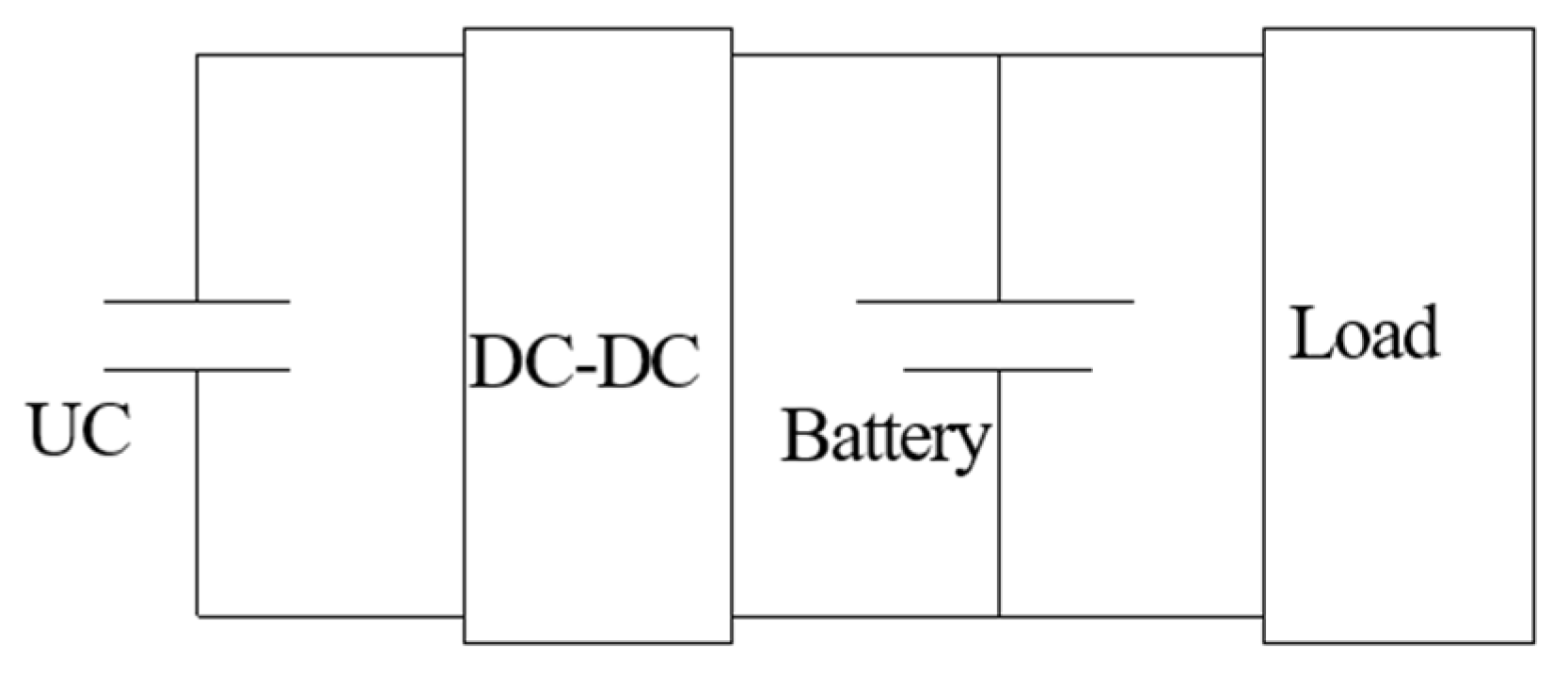
4.3. Topological Structure of Hybrid Energy Storage System

There are many studies on the topology structure of hybrid energy storage systems, and most researchers are mainly concerned about the specific topology structure used. There is currently no standard rule on how to evaluate the advantages and disadvantages of various structures. The topology of the hybrid energy storage system shown in Figure 5 is used in this article.
The battery is directly connected to the inverter, and the ultracapacitor is connected in parallel with the battery through a bidirectional DC-DC converter. Due to the smoother range of voltage variation at the battery end compared to the ultracapacitor, the output voltage of the inverter can remain relatively stable. The DC-DC converter detects the terminal voltage of the battery, adjusts the voltage of the ultracapacitor, and matches the two to work. This structure is relatively easy to control and allows for a wide range of voltage changes for ultracapacitors.

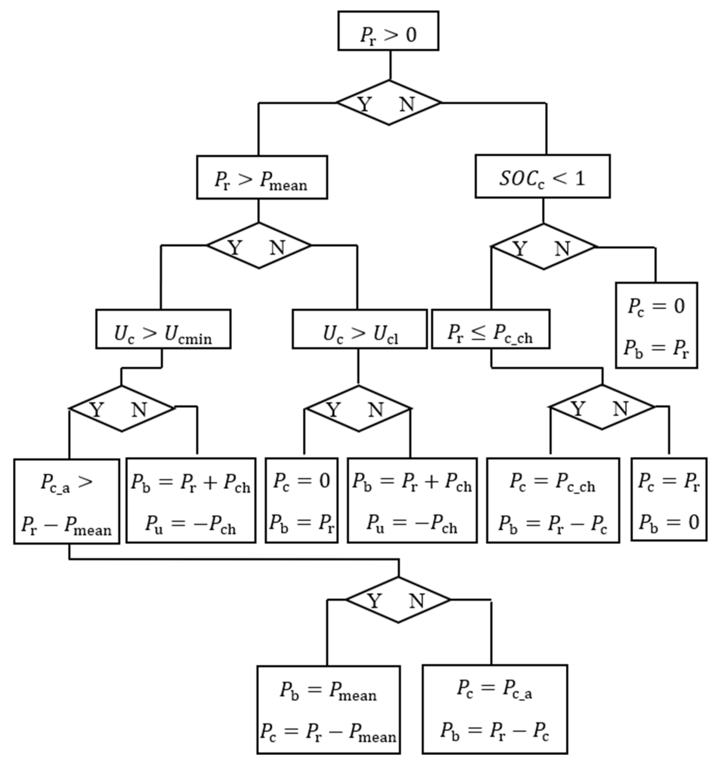
4.4. Hybrid Energy Storage System Control Strategy and Parameter Matching

As shown in Figure 6, the rule-based controller is used in this article. Based on the vehicle’s total energy demand P r , the upper limit of power provided by the battery separately P m e a n , the charging power of the battery to the ultracapacitor P c h , the ultracapacitor can provide power P c _ a , rechargeable power P c _ c h , bottom line voltage U c m i n , balanced voltage U c l , and S O C c to develop rule-based control strategies. When driving, if P r P m e a n , the battery operates independently; when P r > P m e a n , the battery and ultracapacitor work together; during braking, ultracapacitors are given priority in recovering braking energy.
Figure 7 shows the energy consumption and battery life of the entire vehicle when using different P m e a n and P c h . Assuming the total energy consumption of the vehicle is x 1 and the reciprocal of battery cycles is x 2 , the multi-objective function regarding the vehicle energy consumption and battery cycles can be described as:
x 1 + γ x 2
where γ is the weight factor.
Due to the use of ultracapacitors increasing vehicle mass and energy consumption, the main goal should be to reduce vehicle energy consumption, taking into account the improvement of battery life and obtaining the control parameters P m e a n = 25 kW and P c h = 0 kW for the lowest energy consumption.
The above control parameters are used to simulate 166 LiFePO4 batteries with different numbers of ultracapacitors, as shown in Figure 8. As the number of ultracapacitors increases, the energy consumption of vehicles also increases. This is due to the increase in energy system mass caused the use of ultracapacitors, resulting in an increase in overall vehicle energy consumption. The cycle life of the battery first significantly improved, reaching its optimal value at 308 ultracapacitors, and then the overall energy consumption of the vehicle significantly increased. After reaching its optimal value, the cycle life of the battery began to decline.
Here, 308 ultracapacitors with the highest increase in battery cycle times are selected. The parameters of single energy and hybrid energy storage systems are shown in Table 6.

5. Simulation Discussion

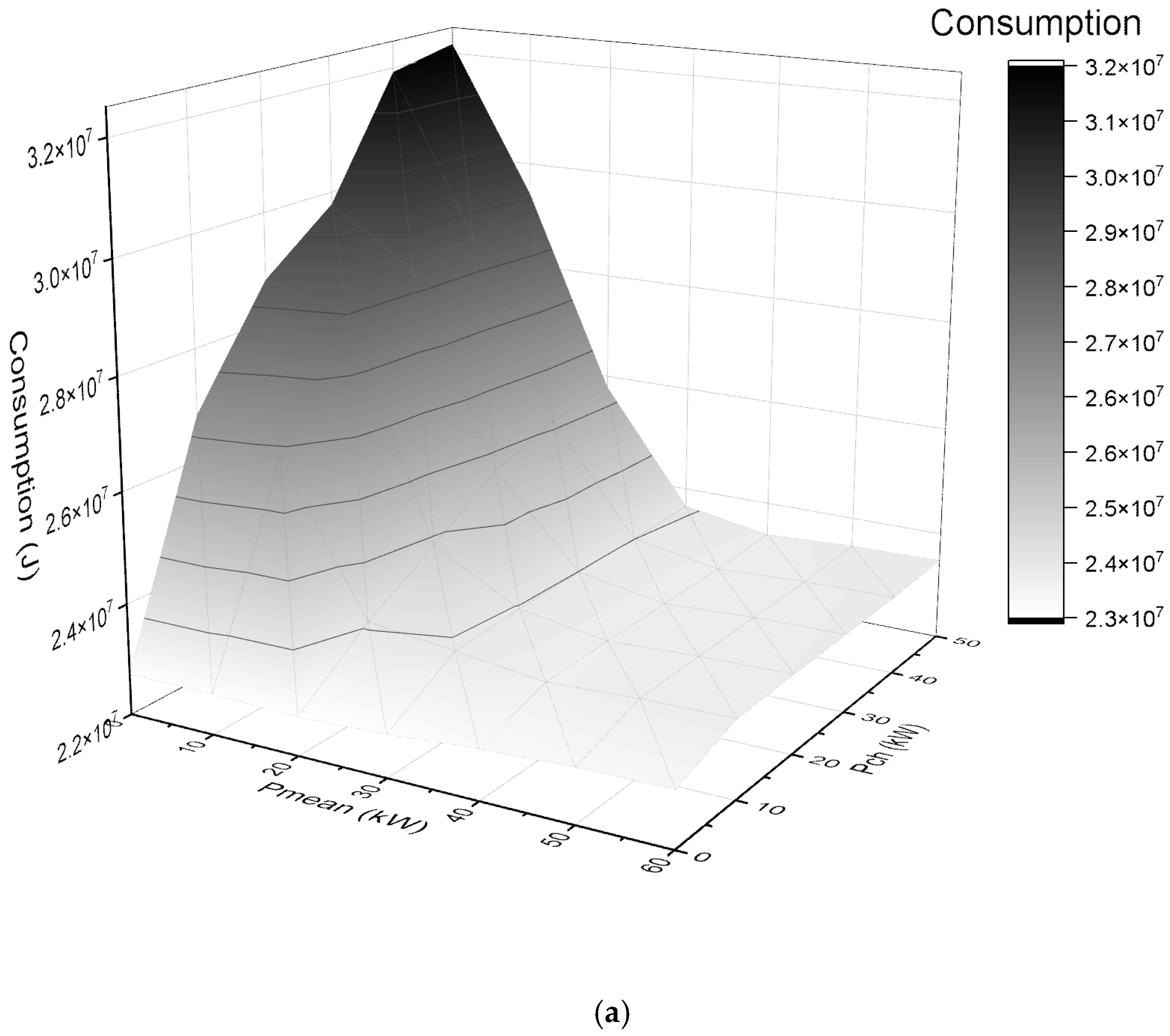
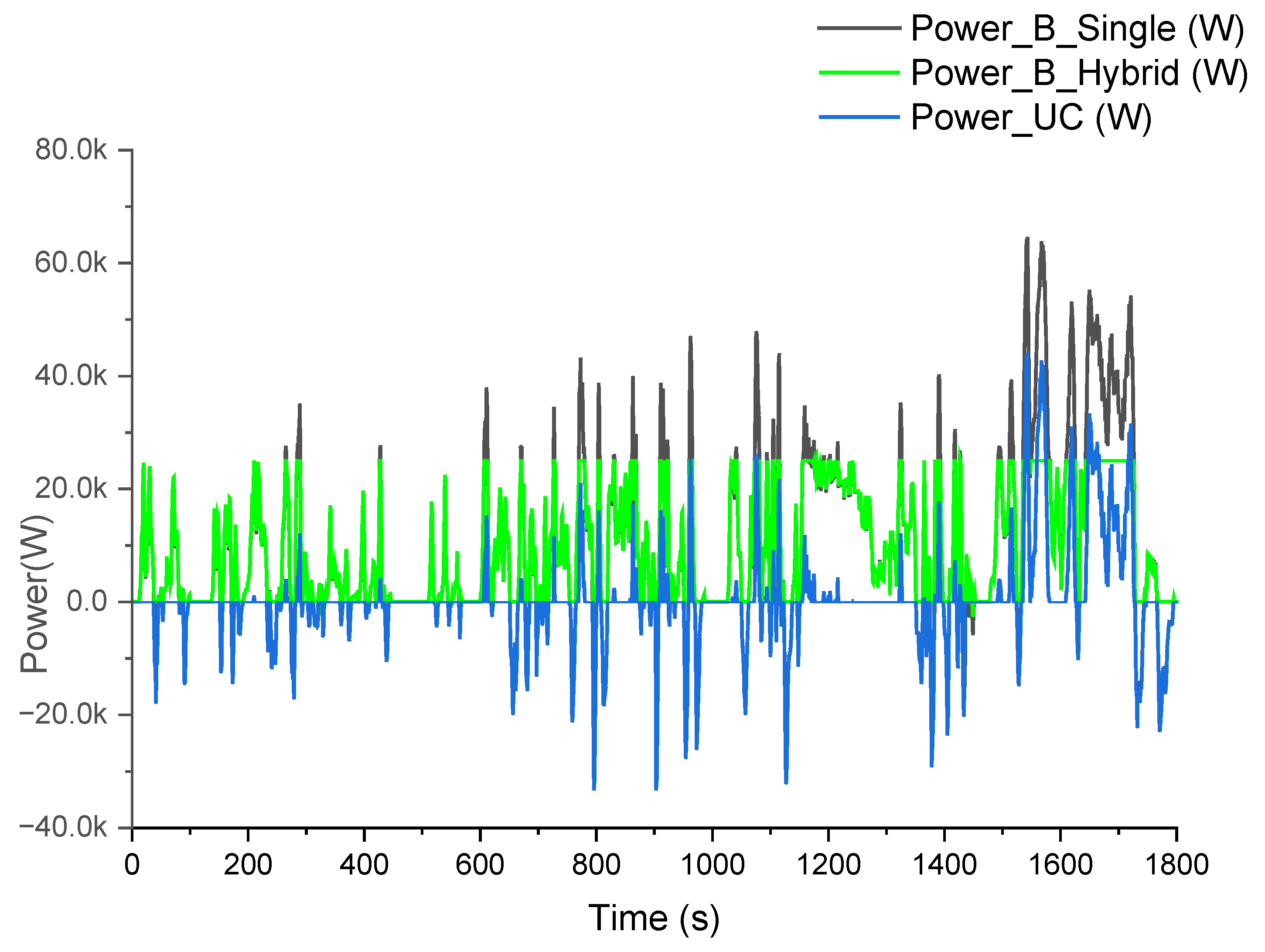
5.1. Battery and Ultracapacitor Power Demand

As shown in Figure 9, compared to a single energy source, the peak driving power of the battery is significantly reduced, and the regenerative braking power is almost zero. The ultracapacitor provides peak power when the driving power exceeds 25 kW and bears almost all braking power during regenerative braking. The ultracapacitor is repeatedly charged and discharged throughout the entire operation process, absorbing regenerative braking energy. Under the control strategy adopted, the hybrid energy storage system can reasonably allocate power between batteries and ultracapacitors, leveraging their respective advantages.

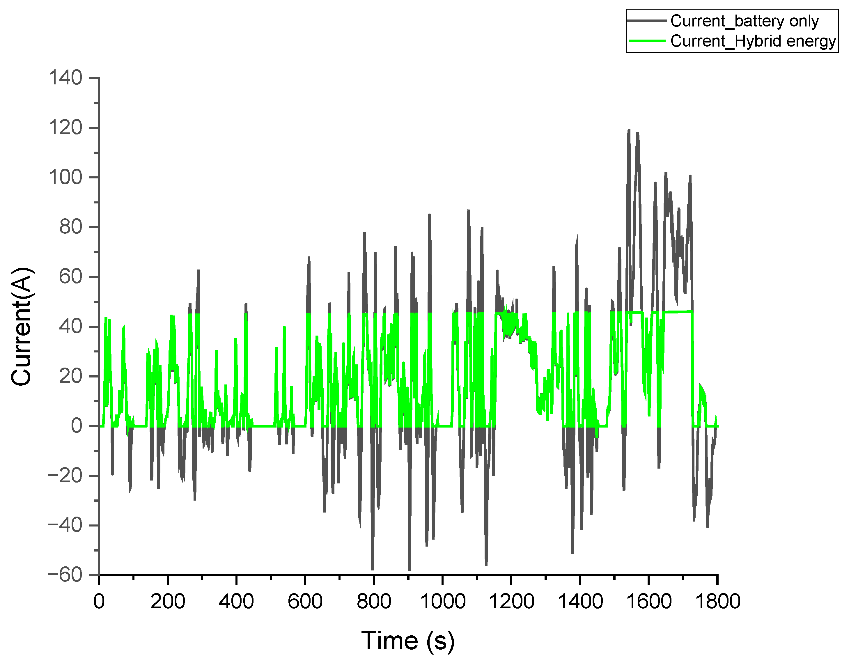
5.2. Battery Current and Efficiency

By using the hybrid energy storage system, the charging and discharging currents of the battery are significantly reduced. The maximum discharge current and maximum charging current are reduced by 61.43% and 91.62%, respectively, compared to a single energy source, as shown in Figure 10. Reducing the charging and discharging current can reduce battery loss and improve battery efficiency.
From Formulas (14) and (15), it can be seen that the battery discharge efficiency η b _ d and charging efficiency η b _ c are inversely proportional to the charging and discharging current of the battery. The higher the current, the more power is consumed in the internal resistance of the battery and the lower the efficiency of the energy system. That is to say, the hybrid energy storage system can reduce battery losses and improve battery efficiency by reducing battery charging and discharging currents. The simulation results show that compared with a single battery energy system, the hybrid energy storage system improves the discharge efficiency of the power battery from 87% to 98%. On the other hand, in the hybrid energy storage system, the ultracapacitor absorbs almost all regenerative braking power. Due to the high efficiency of the ultracapacitor, the charging efficiency of the energy system is also improved and the overall efficiency of the energy system is improved.

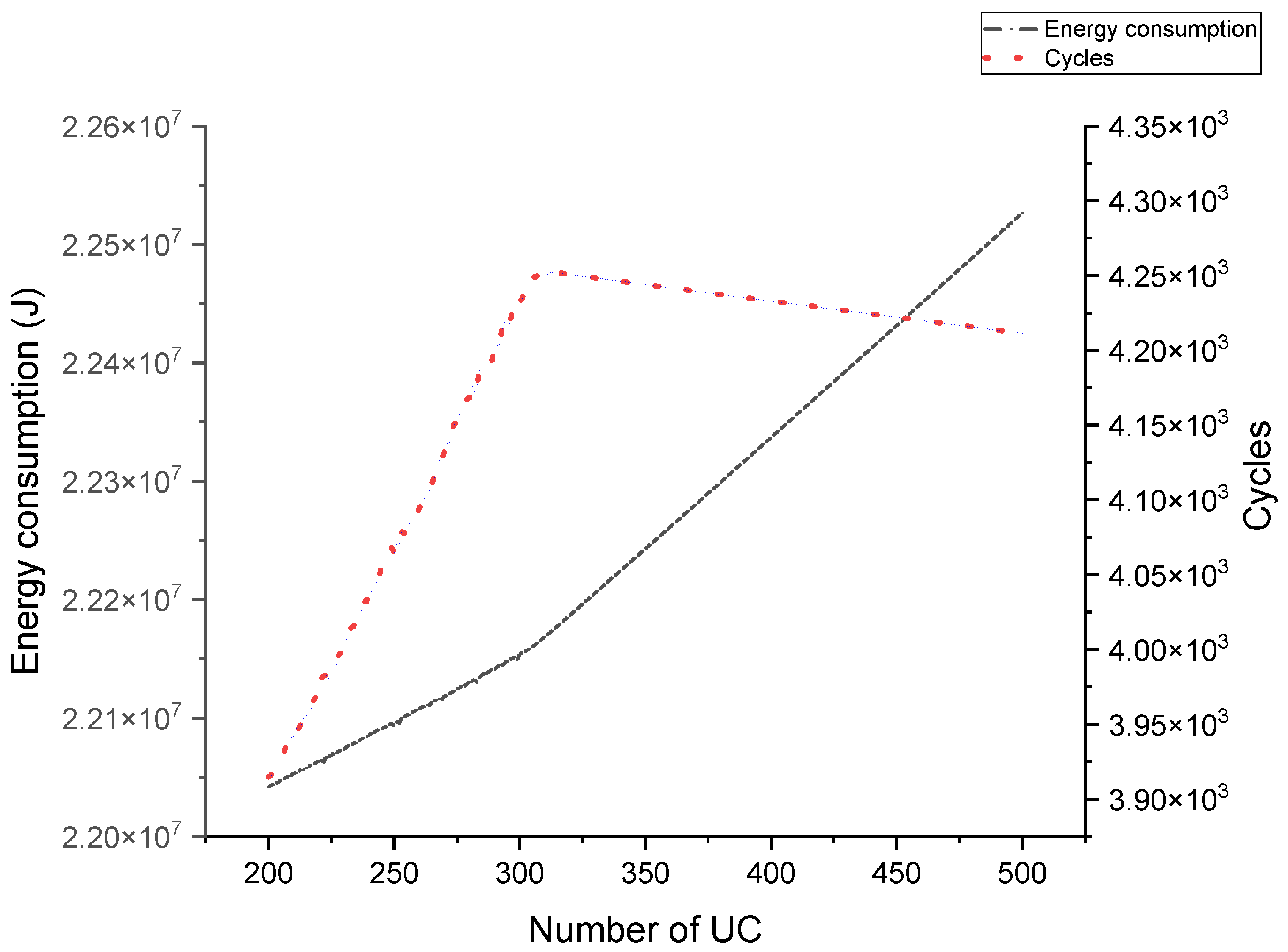
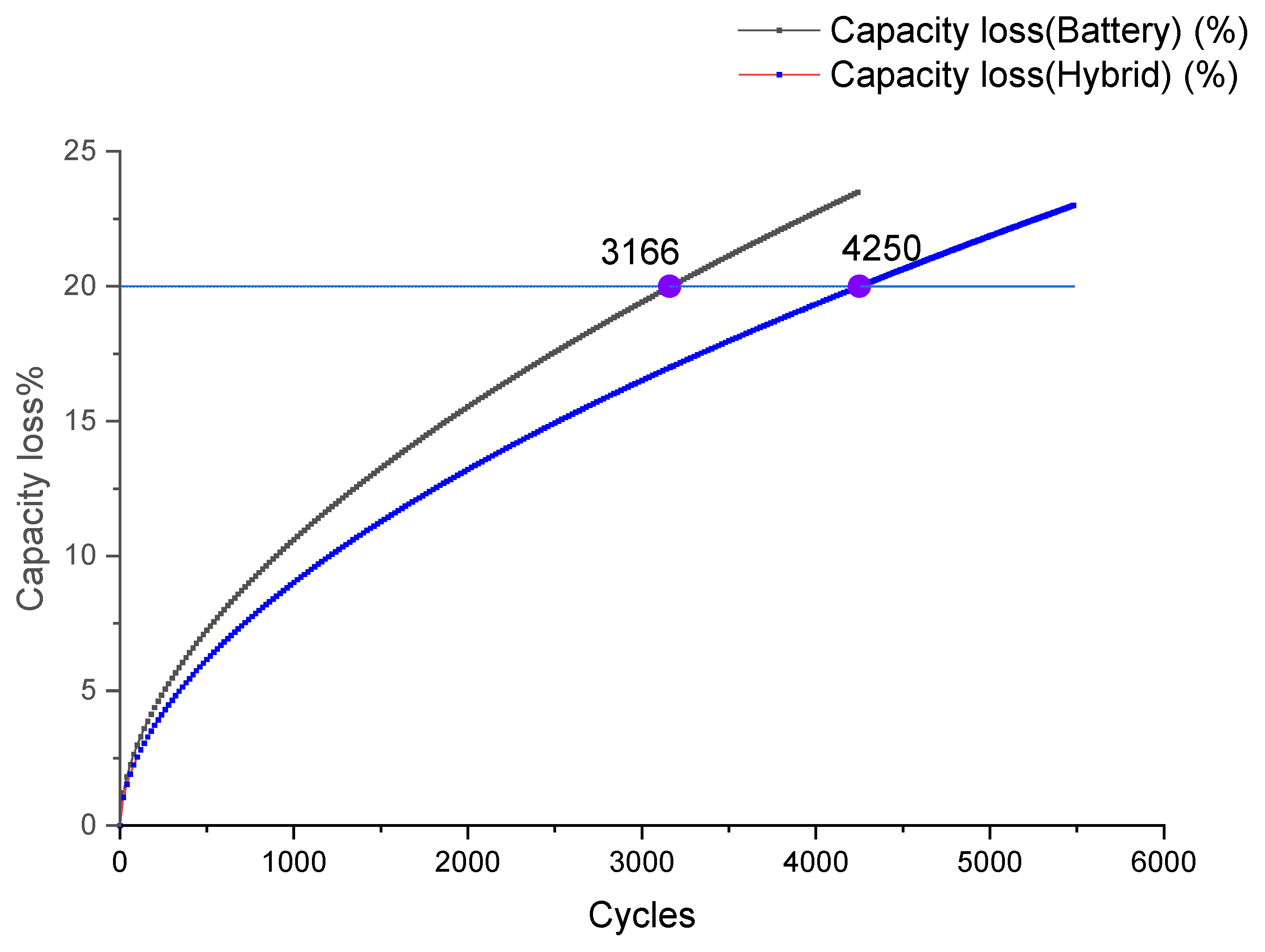
5.3. Battery Cycle Life

Based on the battery current of different energy systems (as shown in Figure 10), the method given in Section 3 is used to estimate the battery cycle life under driving cycle conditions. As shown in Figure 11, with the use of the hybrid energy storage system, the cycle life of the battery has been increased from 3166 to 4250 cycles (capacity has decreased to 20%), the cycle life has been increased by 34.24%, and under the WLTC drive cycle, the driving range has been increased from 73,767.80 km to 99,025.00 km.
According to the current market price, the LiFePO4 battery is approximately 600 yuan/kW·h at present and a company has laid out over 1500 battery replacement stations in China. The latest data show that it took 102 days to switch from 20 million times to 25 million times, with an approximately average of 50,000 times per day. According to a conservative estimate of 50,000 vehicles, adopting hybrid energy storage system technology can save battery costs of over CNY 700 million, as shown in Table 7.

6. Conclusions

In this work, in order to improve the cycle life of replaceable battery electric vehicle batteries, a hybrid energy storage system is composed of ultracapacitors and batteries and parameter matching and control optimization are carried out on the hybrid energy storage system. In order to more accurately estimate the battery cycle life under driving cycle conditions, a proven cycle life model of a LiFePO4 battery at a fixed discharge rate was adopted, and on this basis, the battery cycle life model under driving cycle conditions was deduced. The simulation results show that the optimized hybrid energy storage system can extend the cycling life of the original vehicle battery by 34.24% under WLTC driving cycle conditions, greatly saving the operating costs of battery replacement for automotive companies.
The main contribution of this article is to provide a systematic method and tool for extending the battery cycle life of replaceable battery electric vehicles using a hybrid energy storage system. By using the method provided in this article, it is possible to quickly optimize the design of hybrid energy storage systems under various driving cycle conditions and provide estimated battery cycle life results. In addition, the method provided in this article has certain universality and can be used to study various electric vehicles.
It should be pointed out that the simulation results of this article are based on the control rule parameters formulated based on the average driving power demand of the WLTC driving cycle. It is not the optimal solution, which means that the advantages of different energy sources in hybrid energy storage systems have not been fully utilized. To further leverage the advantages of hybrid energy storage systems, global optimization algorithms can be used to obtain the most optimal control parameters.

Author Contributions

Conceptualization, J.Y.; Methodology, J.Y. and W.Z.; Software, J.Y. and W.Z.; Validation, J.Y. and W.Z.; Formal analysis, W.Z.; Investigation, W.Z.; Resources, J.Y. and W.Z.; Data curation, W.Z.; Writing—original draft preparation, W.Z.; Writing—review and editing, W.Z. All authors have read and agreed to the published version of the manuscript.

Funding

This research was funded by Key Natural Science Research Projects in Higher Education Institutions in Anhui Province (No. KJ2021A0880 and No. KJ2021A0879), and Anhui Science and Technology University Enterprise Cooperation Project: Research and Development of Fuel Cell Cooling System Test Platform (No. 881077).

Data Availability Statement

The data presented in this study are available on request from the corresponding author.

Conflicts of Interest

The authors declare no conflict of interest.

References

  1. Zhang, L.; Hu, X.; Wang, Z. Overview of Supercapacitor Management Techniques in Electrified Vehicle Applications. J. Mech. Eng. 2017, 53, 32–43+69. [Google Scholar] [CrossRef]
  2. Hannan, M.A.; Hoque, M.M.; Mohamed, A.; Ayob, A. Review of energy storage systems for electric vehicle applications: Issues and challenges. Renew. Sustain. Energy Rev. 2017, 69, 771–789. [Google Scholar] [CrossRef]
  3. Hasan, M.K.; Mahmud, M.; Habib, A.K.M.A.; Motakabber, S.M.A.; Islam, S. Review of electric vehicle energy storage and management system: Standards, issues, and challenges. J. Energy Storage 2021, 41, 102940. [Google Scholar] [CrossRef]
  4. Praveena, K.P.S.; Jayalakshmi, N.S.; Kedlaya, A. Energy Management Strategies for Hybrid Energy Storage System in Electric Vehicles: A Review. In Proceedings of the 2020 IEEE International Conference on Electronics, Computing and Communication Technologies (CONECCT), Bangalore, India, 2–4 July 2020. [Google Scholar]
  5. Wu, Z.; Zhang, J.; Wu, H.; Yin, C. Efficiency Analysis of Hybrid Energy Storage System in Light Electric Vehicles. J. Shanghai Jiaotong Univ. 2012, 46, 1304–1309. [Google Scholar] [CrossRef]
  6. Wang, T.; Deng, W.; Wu, J.; Zhang, Q. Power optimization for hybrid energy storage system of electric vehicle. In Proceedings of the Transportation Electrification Asia-Pacific, Beijing, China, 31 August–3 September 2014. [Google Scholar]
  7. Zhang, F.; Hu, X.; Xu, K.; Tang, X.; Cui, Y. Current status and prospects for model predictive energy management in hybrid electric vehicles. J. Mech. Eng. 2019, 55, 23. [Google Scholar] [CrossRef]
  8. Alaoui, C. Hybrid Vehicle Energy Management Using Deep Learning. In Proceedings of the 2019 International Conference on Intelligent Systems and Advanced Computing Sciences (ISACS), Taza, Morocco, 26–27 December 2019. [Google Scholar]
  9. Song, S.; Wei, Z.; Liu, Y.; Lin, Q.; Lin, X. Research on energy management for ultracapacitor/lithium battery hybrid electric vehicles. Control Eng. China 2019, 36, 6. [Google Scholar]
  10. Wei, Z.; Jue, Y.; Wenming, Z.; Fei, M. Research on battery-supercapcitor hybrid energy system for pure electric vehicle. Electr. Meas. Instrum. 2019, 056, 82–90. [Google Scholar]
  11. Asensio, M.; Magallan, G.; Amaya, G.; De Angelo, C. Efficiency and Performance Analysis of Battery-Ultracapacitor based Semi-active Hybrid Energy Systems for Electric Vehicles. Lat. Am. Trans. 2018, 16, 2581–2590. [Google Scholar] [CrossRef]
  12. Dinh, A.N.; Hoang, T.T.; Ta, M.C. Modeling and Control of Electric Vehicles with Hybrid Energy Storage System Using Energetic Macroscopic Representation. In Proceedings of the 2017 IEEE Vehicle Power and Propulsion Conference (VPPC), Belfort, France, 11–14 December 2017. [Google Scholar]
  13. Singh, A.; Pattnaik, S. Design of a Efficient Power Sharing Strategy for a Battery-Ultracapacitor Hybrid Energy Storage System. In Proceedings of the IEEE International Conference on Power Electronics, Intelligent Control and Energy Systems, Delhi, India, 4–6 July 2016. [Google Scholar]
  14. Sadoun, R.; Rizoug, N.; Bartholomeus, P.; Barbedette, B.; Moigne, P.L. Optimal sizing of hybrid supply for electric vehicle using Li-ion battery and supercapacitor. In Proceedings of the Vehicle Power & Propulsion Conference, Chicago, IL, USA, 6–9 September 2011; pp. 1–8. [Google Scholar]
  15. Zhang, L.; Ye, X.; Xia, X.; Barzegar, F. A Real-Time Energy Management and Speed Controller for an Electric Vehicle Powered by a Hybrid Energy Storage System. IEEE Trans. Ind. Inform. 2020, 16, 6272–6280. [Google Scholar] [CrossRef]
  16. Shen, J.; Dusmez, S.; Khaligh, A. Optimization of Sizing and Battery Cycle Life in Battery/Ultracapacitor Hybrid Energy Storage Systems for Electric Vehicle Applications. IEEE Trans. Ind. Inform. 2014, 10, 2112–2121. [Google Scholar] [CrossRef]
  17. Song, Z.; Hofmann, H.; Li, J.; Hou, J.; Han, X.; Ouyang, M. Energy management strategies comparison for electric vehicles with hybrid energy storage system. Appl. Energy 2014, 134, 321–331. [Google Scholar] [CrossRef]
  18. Liu, F.; Wang, C.; Luo, Y. Parameter Matching Method of a Battery-Supercapacitor Hybrid Energy Storage System for Electric Vehicles. World Electr. Veh. J. 2021, 12, 253. [Google Scholar] [CrossRef]
  19. Ferreira, A.A.; Pomilio, J.A.; Spiazzi, G.; Silva, L.D.A. Energy Management Fuzzy Logic Supervisory for Electric Vehicle Power Supplies System. IEEE Trans. Power Electron. 2008, 23, 107–115. [Google Scholar] [CrossRef]
  20. Min, H.; Liu, J.; Yu, Y.; Tian, R. Parameters Optimization and Experiment Study on Ultra-capacitor /Battery Hybrid Energy Storage for a HEV. Automot. Eng. 2011, 33, 1078–1083. [Google Scholar] [CrossRef]
  21. Wang, Q.; Wu, X.; Yu, Y. Optimal matching of HEV with composite electric power supply. J. Jilin Univ. (Eng. Technol. Ed.) 2013, 43, 1153–1159. [Google Scholar]
  22. Djouahi, A.; Negrou, B.; Rouabah, B.; Mahboub, A.; Samy, M.M. Optimal Sizing of Battery and Super-Capacitor Based on the MOPSO Technique via a New FC-HEV Application. Energies 2023, 16, 3902. [Google Scholar] [CrossRef]
  23. Hu, L.; Tian, Q.; Huang, J.; Ye, Y.; Wu, X. Review on Energy Distribution and Parameter Matching of Lithium-ion Battery-super Capacitor Hybrid Energy Storage System for Electric Vehicles. J. Mech. Eng. 2022, 58, 224–237. [Google Scholar]
  24. Jing, C.; Zhang, T.; Yu, Y.; Zhang, L.; Li, X. Study on Emission Characteristics of Hybrid Electric Vehicle Based on NEDC and WLTC Working Cycle. J. Hebei Univ. Technol. 2021, 50, 51–56. [Google Scholar] [CrossRef]
  25. Zhang, W. Theory of Automobile, 3rd ed.; China Machine Press: Beijing, China, 2022. [Google Scholar]
  26. Zeng, X.; Gong, W.; Li, X.; Bai, G. ADVISOR 2002 Electric Vehicle Simulation and Redevelopment Application; China Machine Press: Beijing, China, 2017. [Google Scholar]
  27. Zhang, W.; Yang, J.; Zhang, W. Influence of a New Type of Two-Speed Planetary Gear Automatic Transmission on the Performance of Battery Electric Vehicles. Energies 2022, 15, 4162. [Google Scholar] [CrossRef]
  28. Wang, J.; Liu, P.; Hicks-Garner, J.; Sherman, E.; Soukiazian, S.; Verbrugge, M.; Tataria, H.; Musser, J.; Finamore, P. Cycle-life model for graphite-LiFePO4 cells. J. Power Sources 2011, 196, 3942–3948. [Google Scholar] [CrossRef]
  29. Luo, Y.; Wang, F.; Yu, H.; Liu, X. A Study on the Driving-cycle-based Life Model for LiFePO4 Battery. Automot. Eng. 2015, 37, 881–885. [Google Scholar]
Figure 1. Driving cycles: (a) NEDC, (b) WLTC.
Wevj 14 00248 g001aWevj 14 00248 g001b
Figure 2. Relationship between l n B n and battery discharge rate n.
Wevj 14 00248 g002
Figure 3. R i n t model of LiFePO4 battery.
Wevj 14 00248 g003
Figure 4. Model of ultracapacitor.
Wevj 14 00248 g004
Figure 5. Topological structure of hybrid energy storage system.
Wevj 14 00248 g005
Figure 6. Rule-based controller flowchart.
Wevj 14 00248 g006
Figure 7. Different P m e a n and P c h with vehicle energy consumption and battery cycle life: (a) Vehicle energy consumption; (b) Battery cycle life.
Wevj 14 00248 g007aWevj 14 00248 g007b
Figure 8. The relationship between the number of ultracapacitors and vehicle energy consumption and battery cycle life.
Wevj 14 00248 g008
Figure 9. Battery and ultracapacitor power demand.
Wevj 14 00248 g009
Figure 10. Battery current of different energy systems.
Wevj 14 00248 g010
Figure 11. Battery cycle life of different energy systems, WLTC driving cycle.
Wevj 14 00248 g011
Table 1. Parameter table of replaceable battery electric coupe SUV.
ParametersValue
Curb weight/kg2290
Windward area/ A /m23.368
Wind resistance coefficient/ C d 0.26
Wheel radius/ r /m0.365
Rolling resistance coefficient/ f 0.009
Wheelbase/m2.9
Drive motor power/kW130
Maximum speed of drive motor/rpm12,000
Table 2. NEDC and WLTC driving cycle parameters.
ParametersNEDCWLTC
Time/s11841800
Distance/km10.9323.26
Max speed/km/h120131.32
Average speed/km/h33.2146.49
Max acceleration/m/s21.061.7
The above data are based on software statistics and there may be some discrepancies.
Table 3. Parameter values under different discharge rates.
Discharge Rate B E a z
0.530,33031,5000.552
219,30031,0000.554
612,00029,5000.56
1011,50028,0000.56
Table 4. Parameters of LiFePO4 single battery.
ParametersValue
Mass/kg3.04
Capacity/A·h135
Nominal voltage/V3.2
Charging cut-off voltage/V3.65
Discharge termination voltage/V2.5
Internal resistance/m Ω0.686 < Rint < 0.7080
Cycle life/80%DOD 25 >3000
Table 5. Parameters of Ultracapacitor.
ParametersValue
Mass/kg0.36
Capacity/F2500
Nominal voltage/V2.7
Internal resistance/m Ω0.35
Cycle life>500,000
Table 6. Parameters of single energy and hybrid energy storage system.
Energy TypeNumber of
Batteries
Number of
Ultracapacitors
Energy System
Mass/kg
Battery1660505
Hybrid energy storage system166308505 + 111 (UC)
Table 7. Economic benefit estimation table.
ItemsNumber
Battery pack energy/kW·h71.72
Unit price 10,000 yuan/kW·h0.06
Unit price of battery pack/10,000 yuan4.3
Number of battery exchanges/10,0005
Total price of battery pack/10,000 yuan215,160
Battery cycle life increase/%34.24
Battery savings/10,000 yuan73,668
Disclaimer/Publisher’s Note: The statements, opinions and data contained in all publications are solely those of the individual author(s) and contributor(s) and not of MDPI and/or the editor(s). MDPI and/or the editor(s) disclaim responsibility for any injury to people or property resulting from any ideas, methods, instructions or products referred to in the content.

