1. Introduction
The traditional grid provides voltage and frequency support for the synchronous machine. Nowadays, the power system is changing from traditional fossil energy generation to wind, solar, and other new energy sources. The inertia and frequency support capacity decrease. The electric vehicle is treated as a good adjustable load resource, and how to design and control the converter of the electric vehicle has been focused on. When the new energy vehicle electric drive system is connected to the microgrid on a large scale, the power quality of its grid-connected access and output three-phase power will directly affect the stability of the microgrid [
1,
2]. Therefore, this paper studies the high-reliability pulse width modulation (PWM) strategy and grid-connected control strategy of a new energy vehicle multilevel electric drive system based on a new cascade three-phase bridge inverter, which can improve the output power quality of the electric drive system in the state of energy storage generation, reduce the output harmonics and loss on the transmission line, and enhance the adjustment performance to the disturbance, thus improving the operation stability of the new energy microgrid.
The medium voltage multilevel converter is mainly used to connect the new energy generation or battery to the grid, which can effectively reduce the switching frequency, d
u/dt, electromagnetic interference, and output voltage harmonics [
3,
4]. Multilevel inverters can be divided into single-power type multilevel inverters [
5,
6] and multi-power type multilevel inverters [
7,
8] according to the number of power supplies. Single-power multilevel inverters mainly include capacitor types [
9], diode types [
10], hybrid clamp types [
11], etc. The main advantages of the diode-type multilevel inverter are its simple structure, which can easily control the flow of power; however, it is difficult to equalize the pressure and difficult to expand [
12]. The main advantage of a capacitive-type multilevel inverter is that it can expand multiple levels, and the large number of levels makes the overall efficiency of the inverter high [
13]. However, the more the number of levels, the required capacitance will also increase correspondingly. Then the volume will become huge, and the reliability will deteriorate, which will bring many disadvantages to production. Combining the advantages of the capacitor type and diode type, the hybrid diode and capacitive multilevel inverter has the advantages of the above two inverters, but the number of diodes and capacitors in the case of multilevel is amazing, and the control system is complex [
14]. Based on the above single power supply type, a multilevel inverter with multiple DC power supplies is proposed. Cascaded multilevel inverters are becoming a hot topic in the multilevel converters used in new energy generation systems. The cascaded multilevel converter uses multiple power modules to complete the entire power conversion through superposition, by which the overall output voltage level is improved, but the voltage of each power unit is not large [
15]. The unit of cascaded multilevel inverters is mainly H-bridge cascaded inverters, for which the main modulation strategies are developed based on the mature two-level PWM technology [
16]. Each basic unit of the traditional cascaded H-bridge inverter is a single-phase H-bridge circuit, and its output is only determined by the output power of a DC input unit. There is no energy transfer channel between the three-phase outputs. Therefore, the output power between the three phases will be unbalanced when the output power of multiple DC input units is unbalanced. This imbalance of output power is difficult to adjust through the power complementarity between phases. Additionally, if the output power of one unit is reduced, the power of all other output units can only be synchronously reduced by control to achieve the stability control of the system; otherwise, it will cause the three-phase output imbalance of the electric drive system. The serious imbalance of three-phase output power in the electric drive system will generate more uncontrollable zero-sequence circulation, resulting in more losses in the microgrid system. Additionally, the imbalance of three-phase power will produce more negative sequence components in the system and even cause the wrong trigger of the protection equipment, which seriously affects the stability of the microgrid system. Therefore, improving the power quality of the three-phase output power in the new energy vehicles is of great significance for improving the stability of the microgrid system. The common modulation strategies of multilevel inverters include step wave PWM [
17], carrier wave PWM [
18], and multilevel space vector PWM [
19]. Step-wave PWM modulation is one of the most typical modulation strategies for multilevel inverters. There are two methods of step wave PWM: one is the waveform approximation method, and the other is the specific harmonic elimination method. The step-wave PWM modulation has the advantages of a simple algorithm, a wide modulation ratio, and easy implementation. However, when the signal transmission performance is required to be high, the transmission bandwidth of this control method is narrow and inappropriate. The common carrier PWM methods are carrier phase-shifted PWM (CPS-PWM) [
20], carrier cascade-disposition PWM (CD-PWM) [
21], switching frequency optimization PWM (SFOPWM), and sub-harmonics PWM (SHPWM) [
22]. The CPS-PWM method has strong suppression of low harmonics of output voltage, which makes it the most widely used in CHB multilevel inverters and modular MCC multilevel inverters, while the CD-PWM method has a better suppression effect on high-order harmonics, and its control circuit is relatively simple and easy to implement, which can be applied to most multilevel inverters. Multiple-space-vector modulation is a development based on the conventional SVM, in which n levels can produce 3n switching states. Therefore, the transition of voltage synthesis is smoother, and the resultant flux is closer to the circle in the multiple SVM. However, with the increase in level number, the algorithm of the whole inverter control system will become gradually complicated and difficult to realize.
For cascaded multilevel converters, both the PWM modulation strategy and the grid-connected control strategy will affect the performance of the inverter. The control strategies of multilevel inverters applied in microgrids mainly include constant power (P–Q) control [
23], constant voltage/frequency (V/f) control [
24], droop control [
25], and virtual synchronous generator (VSG) control [
26]. P–Q control generally works in grid-connected mode, in which the microgrid inverter outputs constant active power and reactive power according to reference values. P–Q control has the characteristics of a current source, but the voltage adjustment and frequency adjustment of P–Q control are undertaken by the power grid, which does not participate in the frequency and voltage regulation control and does not provide support to the power grid. The increase in permeability for P–Q controlled inverter power will negatively affect supply, and the power quality and stability of the power grid will be negatively affected. V/F control is mainly used to solve the islanding mode operation of the microgrid by providing a reference voltage and frequency. With changing inverter power, V/F control can always maintain a stable voltage and frequency with voltage source characteristics. Droop control has the characteristics of frequency modulation and voltage regulation with changing loads, which can change the frequency or voltage by regulating active power or reactive power. Droop control can operate in isolated island mode and grid-connected mode, which is more widely used than V/F and P–Q control.
The distributed inverter power supply is integrated into the power grid through a large number of electronic interfaces. Due to the lack of inherent ability to autonomously regulate frequency and voltage in the traditional synchronous generator, it cannot provide the necessary frequency and voltage support for the power grid when a disturbance occurs. Virtual synchronous generator control applies the energy storage unit of the microgrid as the inertial energy storage unit and simulates the electromechanical transient characteristics of synchronous generators in the control strategy of grid-connected inverter. The power supply and load with power electronic interface by VSG control can be compared with the conventional synchronous motor in terms of operation mechanism and external characteristics, so that it can regulate the frequency and voltage independently, and the system with VSG control also has virtual inertia and damping characteristics.
This paper presents the topology structure of the cascaded three-phase bridge inverter applied to a microgrid and constructs the mathematical model of the cascaded three-phase bridge inverter. Based on the voltage and current equations of the multilevel inverter, a novel PWM strategy for cascaded three-phase bridge inverters is proposed in this paper, which is named carrier phase-shifted-distributed PWM (CPSD-PWM). In this paper, the analytical expressions of the harmonic spectrum for CPSD-PWM and CPS-PWM are solved by dual Fourier analysis. Compared with the traditional PWM strategy, the proposed CPSD-PWM strategy can effectively reduce the output harmonics and improve the output balance of the multilevel inverter, by which the multilevel inverter can achieve the adaptive balance of three-phase output power. Additionally, on this basis, this paper studies the control strategy for the three-phase cascaded inverter in isolated island mode and grid-connected operation mode. The output frequency and voltage of the multilevel inverter can be accurately controlled by the active power-frequency regulation and the reactive power-regulation of the VSG control strategy. This paper analyzes the influence of the virtual inertia J and the virtual damping D on the stability of frequency regulation. The experimental platform of a cascaded three-phase bridge inverter is built in this paper, and the proposed CPSD-PWM strategy and multilevel inverter control system with VSG control strategy are verified by the simulation analysis and experimental results.
This paper consists of five sections, the first section describes the development status of modulation strategy and control strategy for cascade multilevel inverter; the second section describes the working principle of the cascaded three-phase bridge inverter, and proposes the carrier phase-shift modulation PWM strategy; the third section describes the working principle and parameter design method of the cascaded three-phase bridge inverter by VSG control strategy; the operation characteristics of cascade three-phase bridge inverter under different working conditions are simulated and analyzed under the proposed modulation strategy and control strategy in the fourth section; and the fifth section is the conclusion, which summarizes the core content of this paper.
2. Carrier Phase-Shifted-Distributed PWM for Cascaded Three-Phase Bridge Inverter
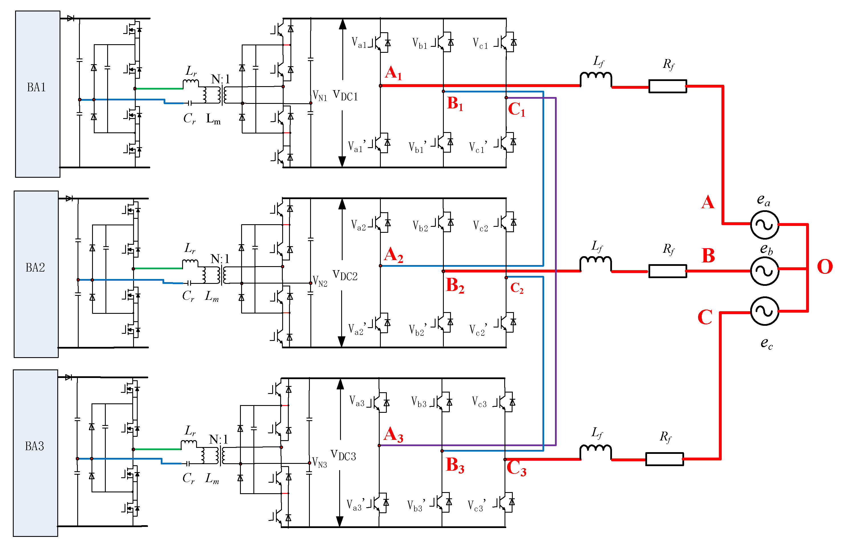
Figure 1 shows a topology diagram of a typical grid-connected battery system in the microgrid.
The front stage of the battery converter system uses an isolated half-bridge LLC converter to transform the electric energy from the battery. Additionally, the rear stage realizes grid-connected battery power generation through the cascaded three-phase bridge inverter. The output power of the half-bridge LLC is used as the isolated DC bus voltage for the cascaded three-phase bridge inverter. The cascaded three-phase bridge multilevel inverter takes the three-phase voltage inverter module as a basic power unit cascaded into a hybrid connection structure form of inverter. Similar to the cascaded H-bridge multilevel inverter, it also makes the AC side output voltage of the inverter present a multilevel state through the superposition of the DC side voltage of the basic module. Compared with the traditional cascaded H-bridge multilevel inverter, the cascaded three-phase bridge multilevel inverter requires fewer switching devices than the former for the same number of output levels. Additionally, the cascaded three-phase bridge inverter is suitable for a three-phase system, which can significantly improve the balance of three-phase output. With the increase of the cascade modules, the number of levels also increases step by step and becomes more similar to the sine wave. The level number S is defined as the steps number of the output line voltage on the inverter AC side, that is, S = 2L + 1, where L is the number of the cascade modules. Therefore, the level number of a two-stage, three-phase inverter is five, which is shown in
Figure 1. The two-stage cascaded inverter is composed of three submodules; each module is connected to an independent battery, and the three line voltages on the AC side of the converter are obtained through the cascade superposition between the submodules.
To build the mathematical model of the cascaded three-phase bridge inverter, the power devices in the cascaded inverter can be simplified by the unipolar binary logic switch function
Skm, which can be defined as:
For a two-stage cascaded three-phase bridge converter, the output line voltage on the AC side can be expressed as:
According to Equation (2), the maximum number of levels of the output line voltage in the two-stage cascade three-phase bridge converter is five, including (−2
VDC, −
VDC, 0,
VDC, and 2
VDC), and its amplitude is 2
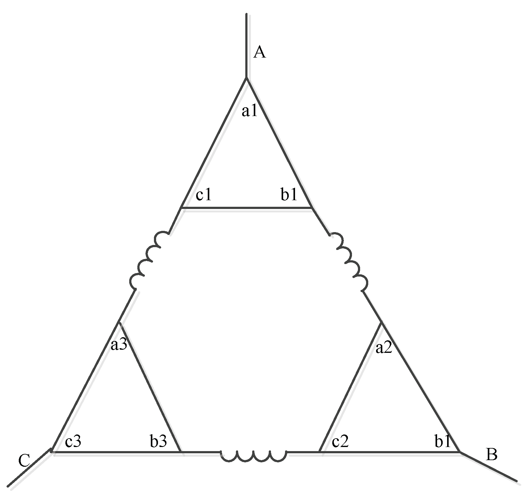
VDC. The equivalent circuit of a two-stage, five-level cascaded, three-phase bridge converter can be seen in
Figure 2, where A–C are the three-phase grid-connected output of the cascaded three-phase bridge inverter, A1–C3 represents the output end of each bridge arm in the cascaded three-phase bridge inverter.)
By using Kirchhoff’s current law, the current relationship between different modules can be expressed as:
where
ikNn (k = a, b, and c, and
n = 1, 2, and 3) is the current of the kth submodule.
If each submodule of the cascade three-phase bridge converter is controlled synchronously and the three-phase current on the AC side is symmetrical, as shown in
Figure 2, it can be seen that the sum of the fundamental wave components of the inner loop current
ia3,
ib1, and
ic2 is 0, that is,
ia3 +
ib1 +
ic2 = 0.
Using Kirchhoff’s voltage law, the phase loop equation of a cascaded three-phase bridge multilevel converter is established as:
where
vkNn (k = a, b, and c and
n = 1, 2, and 3) is the voltage from k
n to the neutral point N
n of the power supply, and
vNOn (
n = 1, 2, and 3) is the voltage from point N
n to the load neutral point O.
R =
Rf +
Rs, where
Rs is the equivalent resistance of the power device and
RL is the equivalent resistance of the synchronous filter inductor.
From Equation (6), the relationship between the switch function is as follows:
As b1 is connected to a2, c1 is connected to a3, and c2 is connected to b3 in the cascaded three-phase bridge inverter, the voltages with O as the reference point can be expressed as:
For a three-phase symmetric system, the voltage and current can be described as:
From Equations (6)–(9), the neutral point voltage can be expressed as:
Furthermore, the voltage of the submodules can be obtained as:
The effective value of the three-phase voltage output by the AC side of the inverter is supposed to be
V, which can be expressed as:
When three modules are in synchronous PWM modulation strategy, the output phase voltage of each submodule can be expressed as:
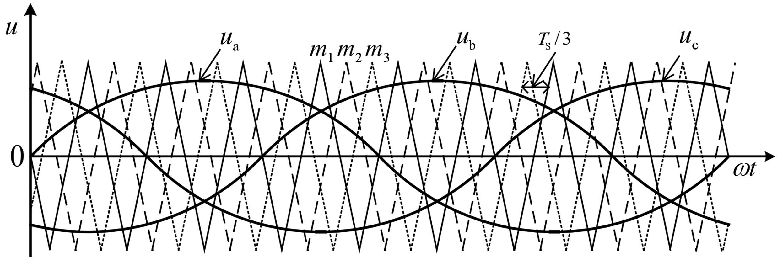
According to the expected output voltage of each submodule, the PWM control signal of each bridge arm can be calculated. The traditional PWM strategy mainly includes sinusoidal pulse-width modulation (SPWM), space vector pulse-width modulation (SVPWM), CPS-PWM, and phase disposition PWM (PD-PWM). SPWM and CPS-PWM are the most commonly used control strategies. SPWM is easy to implement; however, it cannot achieve the multilevel circuit characteristics of a cascaded three-phase bridge inverter. The CPS-PWM strategy of the cascaded multilevel inverter is shown in
Figure 2.
The modulated waves in
Figure 3 are sinusoidal waves
ua,
ub, and
uc. The carrier wave is triangular wave
m1,
m2, and
m3, and its phase lag is
Ts/3 (
Ts is the triangular carrier period). The carrier phase-shifted PWM modulation applies a plurality of triangular carriers with the same amplitude and phase lag at a certain angle to compare with the modulated wave. The generated PWM pulses control each switching device of the multilevel inverter, respectively. The CPS-PWM method is usually applied in the cascade H-bridge inverter, and the cascade H-bridge inverter under the CPS-PWM control method can achieve very good output characteristics.
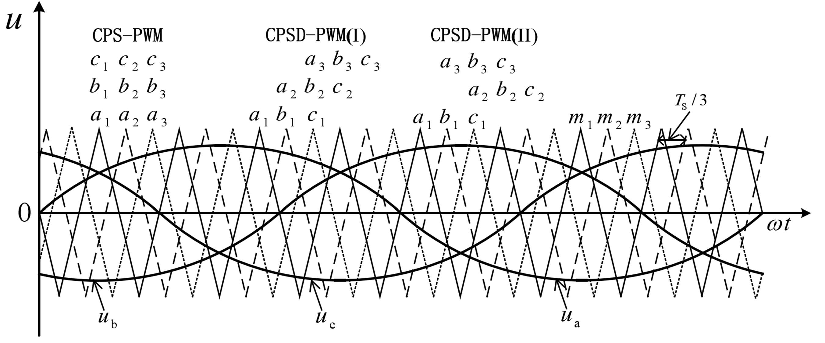
For the cascaded three-phase bridge inverter, the basic unit of the cascade inverter is adjusted from a single-phase H-type circuit to a three-phase half-bridge circuit. Moreover, the connection mode of a basic cascaded unit is also different, and the equivalent circuit of a cascaded three-phase bridge inverter is also different from that of a cascaded H-bridge inverter. Therefore, the traditional CPS-PWM makes it difficult to make the cascaded three-phase bridge inverter circuit work in the best condition. According to the topology and working characteristics of a three-phase bridge inverter circuit, a three-phase bridge inverter system based on carrier phase-shifted-distributed PWM (CPSD-PWM) is proposed in this paper. The proposed CPSD-PWM in this paper is not a combination of traditional CPS-PWM and PD-PWM.
Figure 4 shows the modulation logic of CPSD-PWM for the cascaded three-phase bridge inverter in
Figure 1.
CPSD-PWM makes the carrier signal on each bridge arm within each module lag (or lead) Ts/3 in phase sequence, and the carrier signal on the corresponding bridge arm in each module lag (or lead) Ts/3 in phase sequence, by which the CPSD-PWM can balance carrier signal distribution. The CPSD PWM can be divided into two types depending on the carrier’s selected form. One can be described as ual-N1, which is obtained from ua and m1, ubl-N1, which is obtained from ub and m1, ua2-N2, which is obtained from ua and m2, and ub2-N2, which is obtained from ub and m3. This modulation method is allocated according to the lag Ts/3, which belongs to the class I strategy of CPSD PWM. The other modulation method is allocated according to lead Ts/3, which is named the class II strategy of CPSD PWM. Compared with traditional CPS-PWM, CPSD-PWM mode has a larger cumulative carrier signal difference and is center symmetric, which is more suitable for the cascaded three-phase bridge inverter and effectively improves the three-phase output symmetry of cascaded multilevel inverters. Based on the topological characteristics of a cascaded three-phase bridge inverter circuit, the output power of each phase is provided by a multiphase DC input unit. Therefore, the cascaded three-phase bridge inverter system based on CPSD-PWM control technology proposed in this paper can effectively improve the output symmetry of the three-phase inverter and the balance of three-phase power generation, and even realize the adaptive balance of three-phase output power through the mutual transmission of power generation between different units, which will significantly improve the stability and reliability of the microgrid system.
The PWM output voltage of an inverter can be obtained by variables
x(
t) and
y(
t), where
x(
t) is carrier single, and
y(
t) is fundamental (sinusoidal) single.
where
ωc is the carrier angular frequency and
ωs is the fundamental angular frequency.
For a submodule of the cascaded three-phase bridge inverter, the output voltage of the A-phase bridge arm in the asymmetric regular sampling can be expressed as:
where
M is the modulation ratio and
E is the DC voltage of the submodule.
Based on the double Fourier integral analysis, the time-varying function
vao(
x,
y) can be expressed as a summation of harmonic components:
where
A00 is the DC offset.
A0n and
B0n are fundamental components and base-band harmonics.
Am0 and
Bm0 are carrier harmonics.
Amn and
Bmn are side-band harmonics.
Based on the double Fourier integral analysis, the fundamental component and harmonics can be calculated as
Therefore, the harmonics of the output voltage in the A phase by CPS-PWM can be calculated as:
The harmonics of the output voltage in the B phase of CPS-PWM can be expressed as:
From Equations (19) and (20), the harmonic spectrum of the output line voltage in the cascade three-phase bridge inverter by CPS-PWM can be expressed as:
where intermediate variables
A,
B, and
C can be described as:
However, the harmonics of the output voltage in the B phase by CPSD-PWM can be expressed as:
where α is the phase angle between the carrier and modulated wave.
Therefore, the harmonic spectrum of the output line voltage by CPSD-PWM can be described as:
The Equation (24) shows that, compared with the harmonics of line voltage obtained by CPS-PWM, the mathematical factors ejnθ are added into the expression of each harmonic component for CPSD-PWM, which makes CPSD-PWM have smaller components on the carrier harmonics and side-band harmonics. CPSD-PWM can improve the unbalance of three-phase output, and compared with the traditional CPS-PWM, the CPSD-PWM is more suitable for cascaded three-phase bridge multilevel inverters.
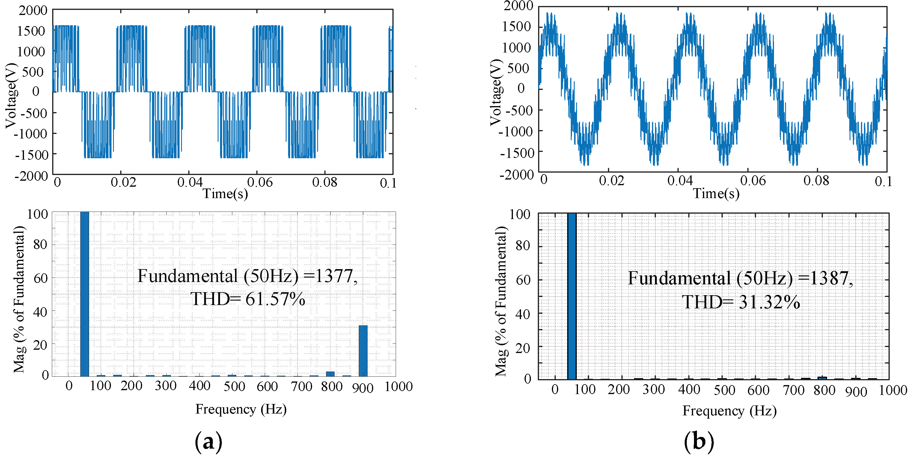
The harmonic characteristics of the output voltage in the cascaded three-phase bridge inverter under different modulation modes are simulated by MATLAB, and the simulation results are shown in
Figure 5.
Figure 5 shows that the traditional three-phase inverter has only two output levels under SPWM, and the harmonic distortion rate of its output voltage is relatively large (THD = 61.57%), which puts forward higher requirements for the design of the filter circuit. Large harmonics at the same switching frequency will directly affect the stability of the microgrid, and the loss of electrical equipment in the microgrid system will also increase. Additionally, the output voltage of the two-level inverter is limited by the voltage level of the power device, and only the power device with a higher voltage level can achieve a higher voltage grid-connected output.
Figure 5 also shows that the cascaded three-phase bridge multilevel inverter with CPSD-PWM in this paper makes the output voltage contain a variety of different levels through the cascade combination of multiple basic units, so that the grid-connected output of high voltage level can be realized through the cascaded power devices of low voltage level. The grid-connected output voltage of a microgrid is no longer limited by the voltage level of power devices. Additionally, the proposed CPSD-PWM strategy can effectively decrease the output harmonics of cascaded three-phase bridge inverters, and the THD is only 31.32% under the same fundamental output. Compared with the traditional inverter by SPWM, the grid-connected output voltage THD of the cascaded three-phase bridge inverter based on CPSD-PWM is significantly reduced by 49.13%, which effectively reduces the design difficulty of the grid-connected filter circuit and improves the operation stability of the microgrid system.
The line voltage and phase current at rated operation by traditional CPS-PWM and proposed CPSD-PWM are shown in
Table 1.
The traditional CPS-PWM strategy is proposed for the cascaded H-bridge inverter structure, which cannot give full play to the topological advantages of the cascaded three-phase bridge inverter. Compared with the traditional CPS-PWM strategy, the CPSD-PWM strategy proposed in this paper can give full play to the topological characteristics of cascaded three-phase bridge multilevel inverters. On the basis of reducing the harmonic distortion rate of inverter output voltage and current,
Table 1 shows that the asymmetry between three-phase outputs can be significantly reduced by more than 99%, and the stability and reliability of electric drive systems can be improved in the state of microgrid-connected power generation. Based on the fact that each phase of the output power of the cascaded three-phase bridge inverter is provided by the multiphase input power supply, the CPSD-PWM strategy proposed in this paper can realize the interconnectivity and conversion of the interphase power. When the three-phase input power is unbalanced, the CPSD-PWM strategy can realize the adaptive adjustment and automatic balance of the three-phase output power, thus significantly improving the output capacity of the electric drive system under abnormal conditions and the stability of the microgrid system operation.
3. Virtual Synchronous Generator Control Strategy for Cascade Three-Phase Bridge Inverters
Compared with the traditional generation system, the output core of the new energy distributed generation system is the power electronic converter, which has no damping or inertia. Therefore, the traditional grid-connected control strategy cannot match the stable requirements of a microgrid. Based on the VSG control strategy, this paper studies the island mode operation and grid-connected mode operation of the cascaded three-phase half-bridge inverter under active power-frequency control and reactive power–voltage control and analyzes the influence of key parameters (virtual inertia J and virtual damping D) in the control strategy on frequency.
This paper ignores the influence of damping winding, the core saturation effect, eddy current loss, and other nonlinear factors on the synchronous generator. Then, when the rotor pole log is equal to 1, the motion equation of a typical hidden pole synchronous generator can be expressed as:
where
J is the rotary inertia and
D is the coefficient of damping.
Tm and
Te are the mechanical torque and electromagnetic torque, and
Pm and
Pe are the mechanical power and electromagnetic power.
ω0 is the angular velocity, which corresponds to the reference frequency.
In the microgrid system, the cascaded three-phase bridge inverter can be equivalent to a synchronous generator, in which the mechanical input power is equivalent to VSG input active power and
Pe is equivalent to VSG output power. Then the
Tm and
Te can be approximately expressed as:
The voltage equation of a typical synchronous generator system can be expressed as follows:
where
uabc and
iabc are the terminal voltage and stator current of each phase winding in the generator, and
if is the rotor excitation current.
R is the resistance of the armature winding,
Ls is the stator inductance, and
Mf is the mutual inductance of the stator windings and rotor windings.
Based on the VSG control strategy, the cascaded three-phase bridge inverter can be equivalent to a typical non-salient synchronous generator, whose mechanical equation and voltage equation can be expressed as:
where
is equivalent electromagnetic electromotive force and
is equivalent terminal voltage.
Ra is equivalent electronic armature resistance, and
Xd is synchronous reactance.
Based on Equation (25), the VSG control strategy applies the stator voltage equation to the cascaded three-phase bridge inverter control to simulate the electromagnetic characteristics of the synchronous generator. Additionally, the rotor motion equation is also used to calculate the power angle of VSG as the voltage phase of the inverter output, by which the frequency control of the inverter output can be realized. Through the active power-frequency control and reactive power–voltage control of the VSG control strategy, the cascaded multilevel inverter can be effectively controlled in island mode and grid-connected mode. Although there is no rotor in the cascaded multilevel inverter, the VSG control brings virtual inertia and virtual damping into the inverter control system, which can reduce the overshoot and accommodation time of active power regulation and suppress frequency oscillation with changing system loads.
- (1)
Active power-frequency control
The VSG control strategy applied the active power-frequency (P-f) control to simulate the synchronous generator primary frequency modulation process. Based on the rotor motion equation of the generator, the synchronous generator frequency adjustment factor can be expressed as:
where
Pref and
ωref are the VSG’s reference power and reference angular frequency, respectively.
The frequency regulation of the VSG can be realized through the virtual frequency modulator, and the frequency modulation control expression of the VSG can be expressed as:
where
Pm is the output active power of the inverter,
Pref is the reference active power, and
ω is the angular frequency of the inverter output.
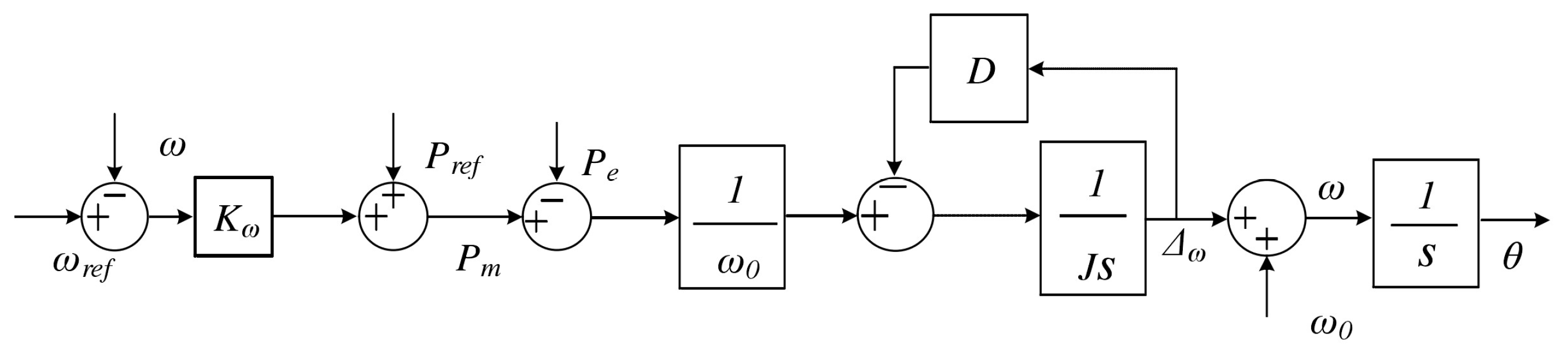
From Equations (28)–(30), the VSG control strategy applies active power-frequency control to realize the primary frequency modulation process on the cascade three-phase bridge inverter, which is shown in
Figure 6.
- (2)
Reactive power–voltage control
The synchronous generators regulate voltage by field current, which can be ex-pressed:
where
G(s) is the transfer function of the field current regulator,
Uref is the reference voltage, and
U is the output voltage.
The VSG control strategy makes the multilevel inverter simulate the reactive power–voltage droop characteristics of a synchronous generator with primary voltage regulation, which can be described as:
where
Dq is the droop coefficient of reactive power–voltage characteristics.
Qref is the reference reactive power, and
Q is the actual reactive power.
Since VSG does not need to control the excitation current; it only needs to make the multilevel inverter simulate the droop characteristic of SG, the VSG control can apply the voltage amplitude E directly equivalent to the excitation current. Then the reactive power–voltage expression of VSG control can be expressed as:
where
K is the integration coefficient.
To eliminate the static difference, the reactive power–voltage control can be im-proved as:
where
Kp and
Ki are the parameters of the PI controller.
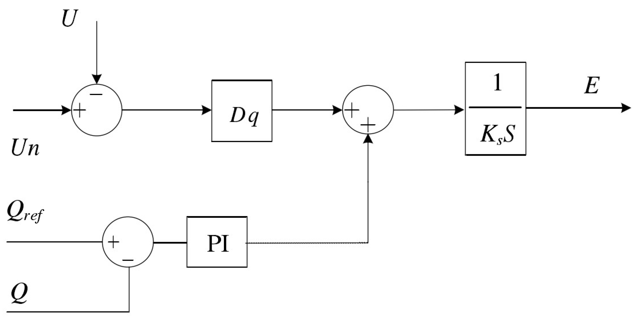
From Equation (34), the reactive power–voltage control of the VSG control strategy is shown in
Figure 7.
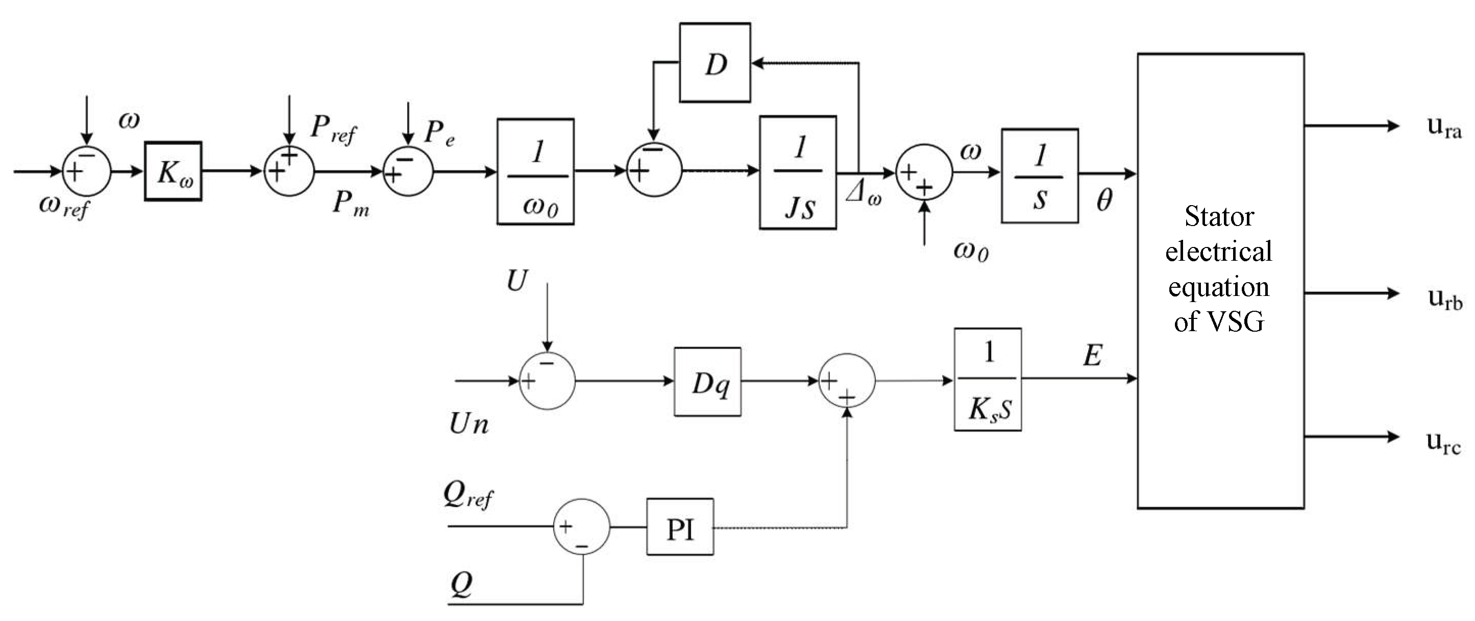
Based on Equations (28) and (34), the VSG control strategy for the cascade three-phase bridge inverter can accurately adjust the amplitude and frequency of the inverter output through active power-frequency control and reactive power–voltage control, which are shown in
Figure 8.
The VSG control strategy can import inertia into the cascaded three-phase bridge inverter, which is important to the power system. However, inertia and damping will also affect the system’s performance. The increasing inertia will reduce the damping ratio of the system and aggravate the active power pulsation, and the introduction of damping will increase the frequency-droop coefficient of the VSG. Therefore, reasonable settings of inertia and damping coefficient can take advantage of VSG control compared with sagging control for the multilevel inverter.
From Equations (29) and (31), the relationship between
P-ω and the rated speed can be expressed as:
The power frequency characteristics of VSG can be regarded as a first-order inertia link whose dynamic response time is determined by Kω, J, and D. Therefore, both J and D need synchronous, comprehensive optimization to achieve the best system performance.
The VSG control strategy is composed of the active power-frequency controller and the reactive power–voltage controller. The active power-frequency controller is used as the virtual governor, and the reactive power–voltage controller is applied as the electrical exciter. The VSG controller forms a feedback system of speed and voltage and then uses the active power-frequency controller and reactive power–voltage controller to adjust the mechanical power and excitation voltage of the prime mover in real time to maintain the stability of the system frequency and voltage. The active power-frequency and reactive power–voltage controllers applied to cascade three-phase bridge inverter systems, which are discussed in
Figure 8, can be directly used as virtual synchro controllers in theory. However, it is difficult to optimize the parameters of the VSG controller. Because the inertia parameters, damping coefficient, and sag coefficient of the synchronous generator cannot be directly introduced into the controller. Therefore, a design method for key control parameters for the VSG controller is presented in this paper. As Equation (32) shows, although the damping component can improve and optimize the power loop and enhance the damping effect of the system, the value of the D component is relatively limited and cannot be increased indefinitely. Therefore, the damping coefficient needs to be considered together with the inertial component. For this reason, the active power-frequency controller loop can be simplified as a second-order system based on
Figure 6. The damping ratio and undamped oscillation angular frequency of this second-order system are related to the damping coefficient and inertia coefficient of the synchronous generator. Therefore, the damping ratio and undamped oscillation angular frequency of the second-order system can be designed to meet the performance requirements of the grid-connected system. This paper designs the grid-connected system with the VSG controller as an underdamped system. On this basis, the damping coefficient and inertia coefficient in the VSG control strategy can be calculated by algebraic calculation. The reactive power–voltage controller achieves voltage control of synchronous generator reactive power. When the reactive power–voltage controller works in the grid-connected mode, the voltage is clamped by the large grid, and only the specified reactive power needs to be delivered to the grid; when the reactive power–voltage controller operates independently with a load in the island mode, the output reactive power is determined by the load size, and voltage support needs to be provided to control the output voltage of the inverter. The key parameter in the reactive power–voltage controller is
Dq, which can be calculated according to the typical parameter of synchronous generators with the same power capacity as the virtual synchronous generator. Thus, the key control parameters of a cascaded three-phase bridge inverter based on the VSG control strategy are designed.
4. Simulation and Experimental Results
The performance of the two-stage, three-phase bridge inverter system in island and grid-connected operation is simulated and analyzed by the Simulink software. The simulation parameters of the system in island mode are shown in
Table 2- (1)
Simulation in the island mode
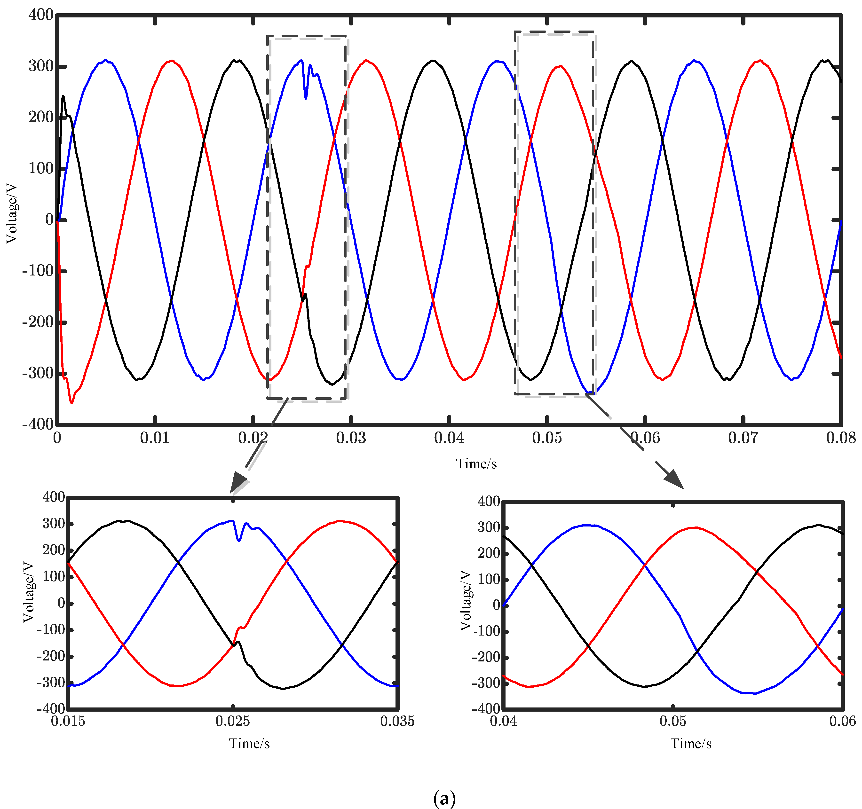
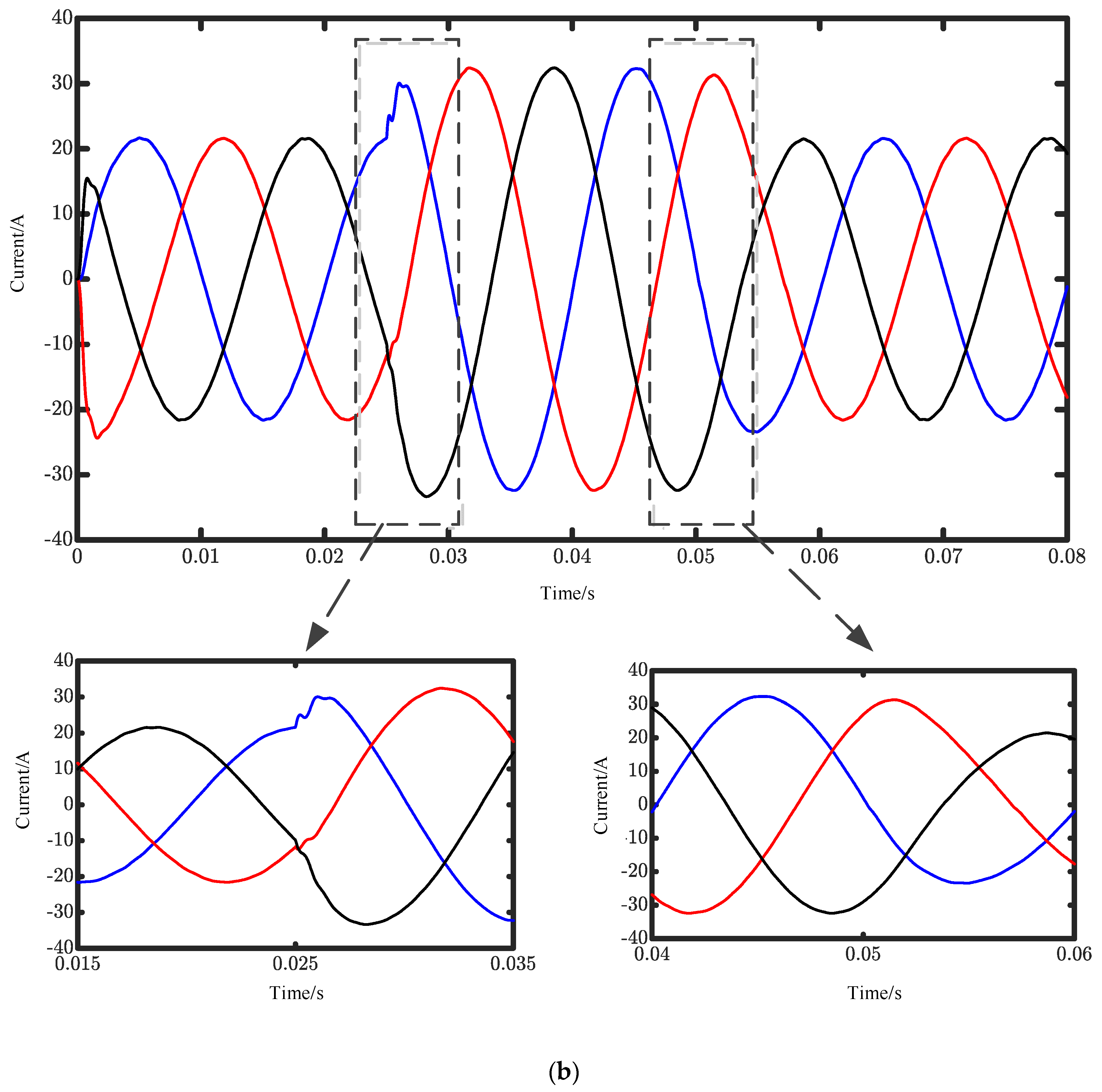
The initial load power of the microgrid system is set as P = 10 kW and Q = 500 var in the island operation mode, and the system power is set as P = 15 kW and Q = 1000 var, which are connected to the microgrid system at 0.025 s, and the load is disconnected from the microgrid system at 0.05 s. The simulation results of the multilevel inverter are shown in
Figure 9.
Figure 9 shows that the output voltage and current of the multilevel inverter controlled by the VSG control are the standard three-phase sine wave. The voltage and current only fluctuate slightly at the moment when the load is added and removed, and they instantly recover to stable voltage and current. As the load is increased at 0.025 s,
Figure 9 shows that the inverter output voltage remains constant and the current amplitude increases from 21 A to 31 A, which shows the frequency–voltage control characteristics of the VSG control. The system adjustment time under variable load is 0.0055 s.
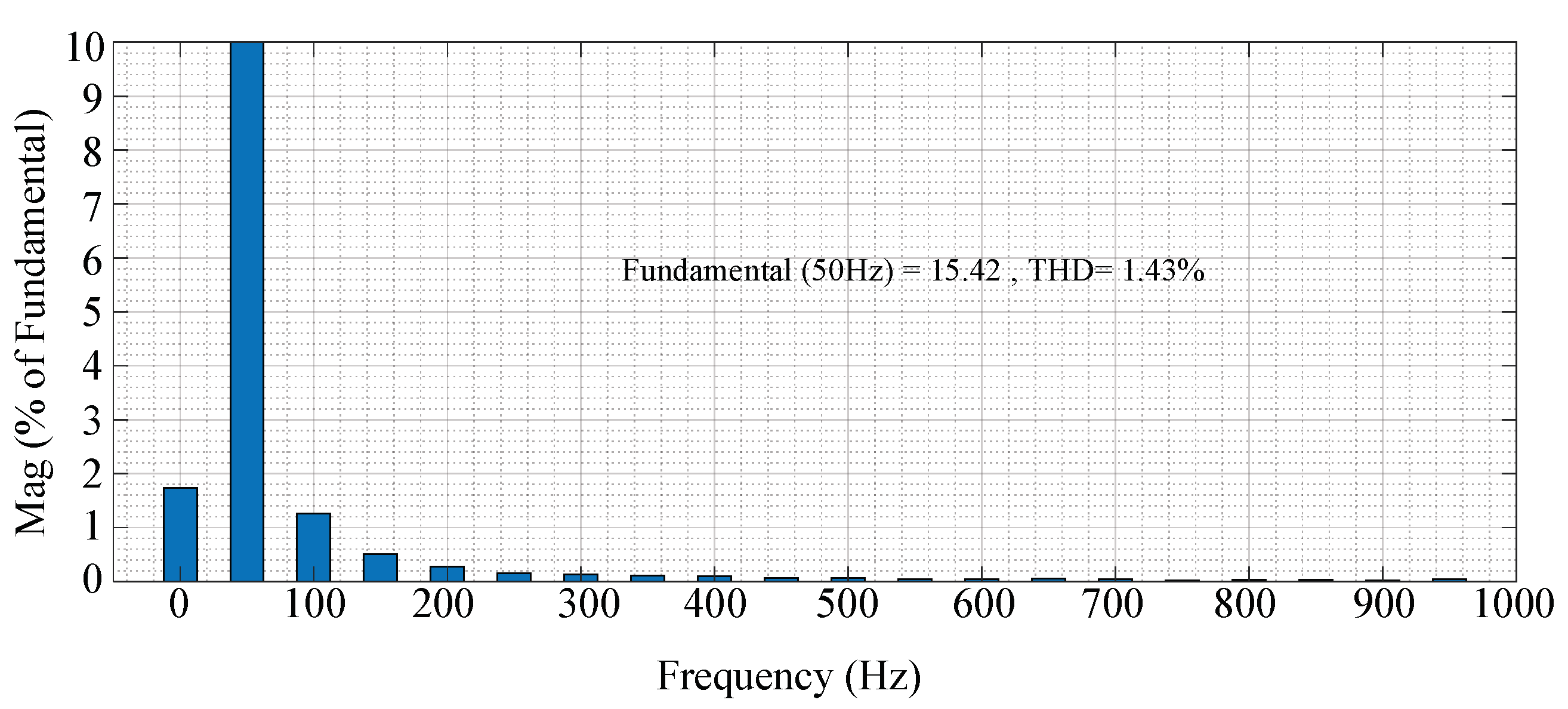
Figure 10 shows the simulation results of THD analysis for the A-phase current waveform. It can be seen from
Figure 10 that the THD of the phase A current waveform is less than 5%, which meets the requirements of the power microgrid.
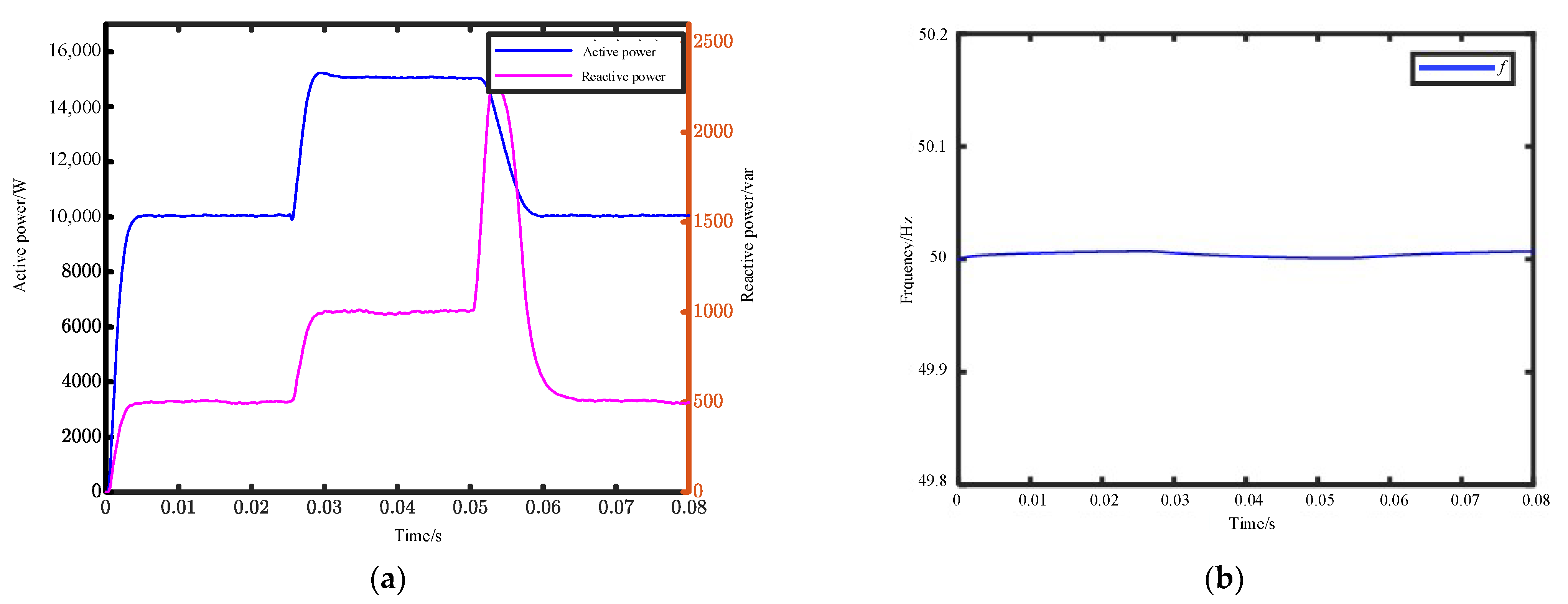
Figure 11 shows the simulation results for active power and power factor, which increased rapidly at the beginning of the simulation. After a short time, the system output achieves a stabilized active power of 10 kW and a reactive power of 500 var. Then the active power is increased to 15 kW and the reactive power is increased to 1000 var when the system is connected to the microgrid system for 0.025 s. Additionally, the load is removed, and the active and reactive power are restored immediately.
Figure 10 shows the system enters a steady state after a period of simulation time, and the active and reactive power adjustment time under variable load is 0.0055 s. Whether the load changes or not, the frequency remains basically unchanged at 50 Hz. Additionally, even if the load is switched, the fluctuation of the system frequency is less than 0.01 Hz, which meets the needs of a microgrid connection.
- (2)
Simulation in the grid-connected mode
The simulation condition of a multilevel inverter system in grid-connected mode is set to 1 s. The reference power of the microgrid system is
Pref = 100 kW,
Qref = 0 var, and the grid-connected voltage is 220 V in the initial state. At 0.5 s, the reference power increases to
Pref = 110 kW and
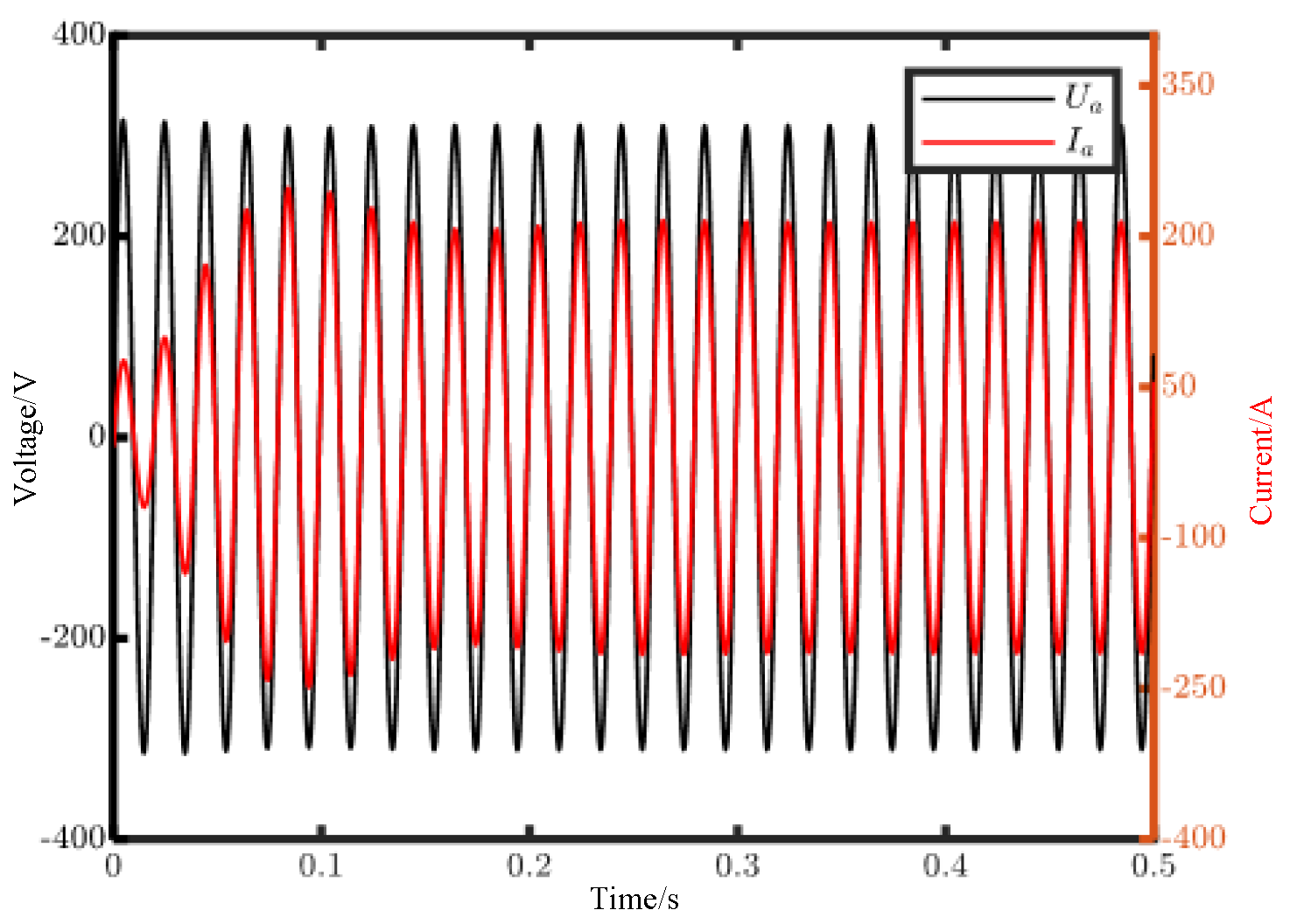
Qref =0 var. Simulation results of phase voltage and current at 0–0.5 s are shown in
Figure 12.
Figure 12 shows that the inverter output voltage quickly becomes stable at 220 V after the cascaded inverter connects to the grid. Additionally, the current reaches a steady state at 0.25 s, and then the current is kept at 214.27 A. In the process of dynamic regulation, the overshoot of the current is less than 10%.
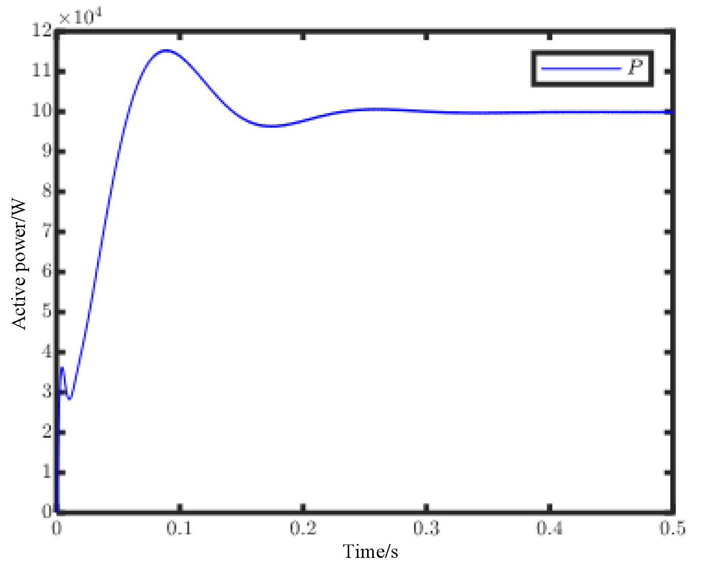
Figure 13 shows that the system reaches a steady state at 0.25 s after a short transition and stabilizes at 100 kW. It can be seen that the phase voltage and current are always in the same phase, and the power factor is 1. The current distortion degree of grid-connected current is lower with the VSG control than with the traditional double-loop control, and the THD values are 0.78%. All these performances meet the IEEE standard 519-2014.
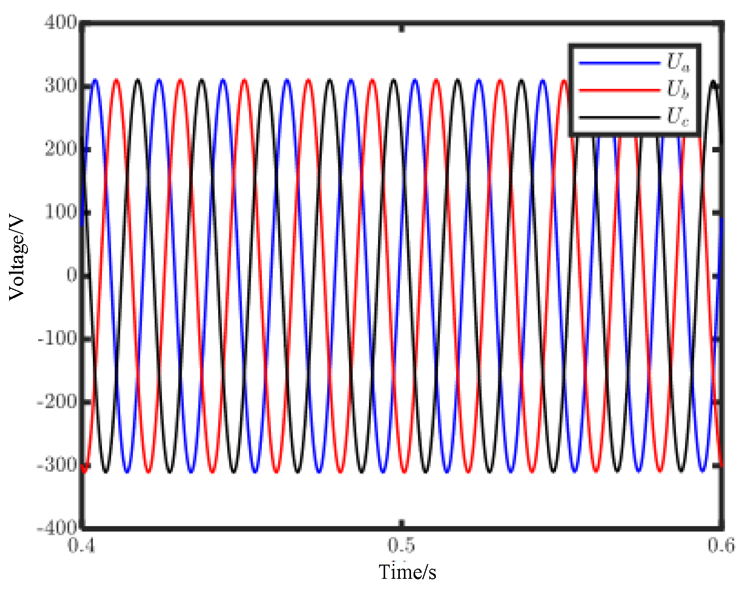
Figure 14 shows that the voltage remains at 220 V whether the active power changes at 0.5 s. Additionally,
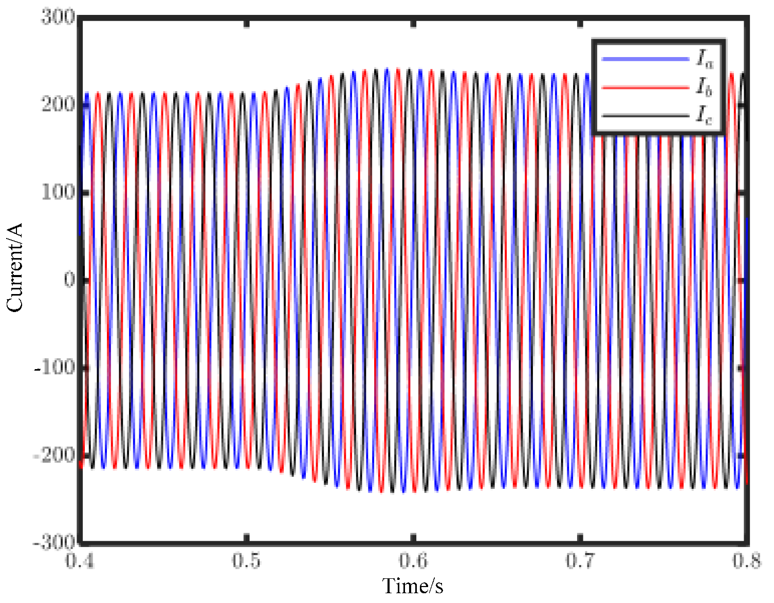
Figure 15 and
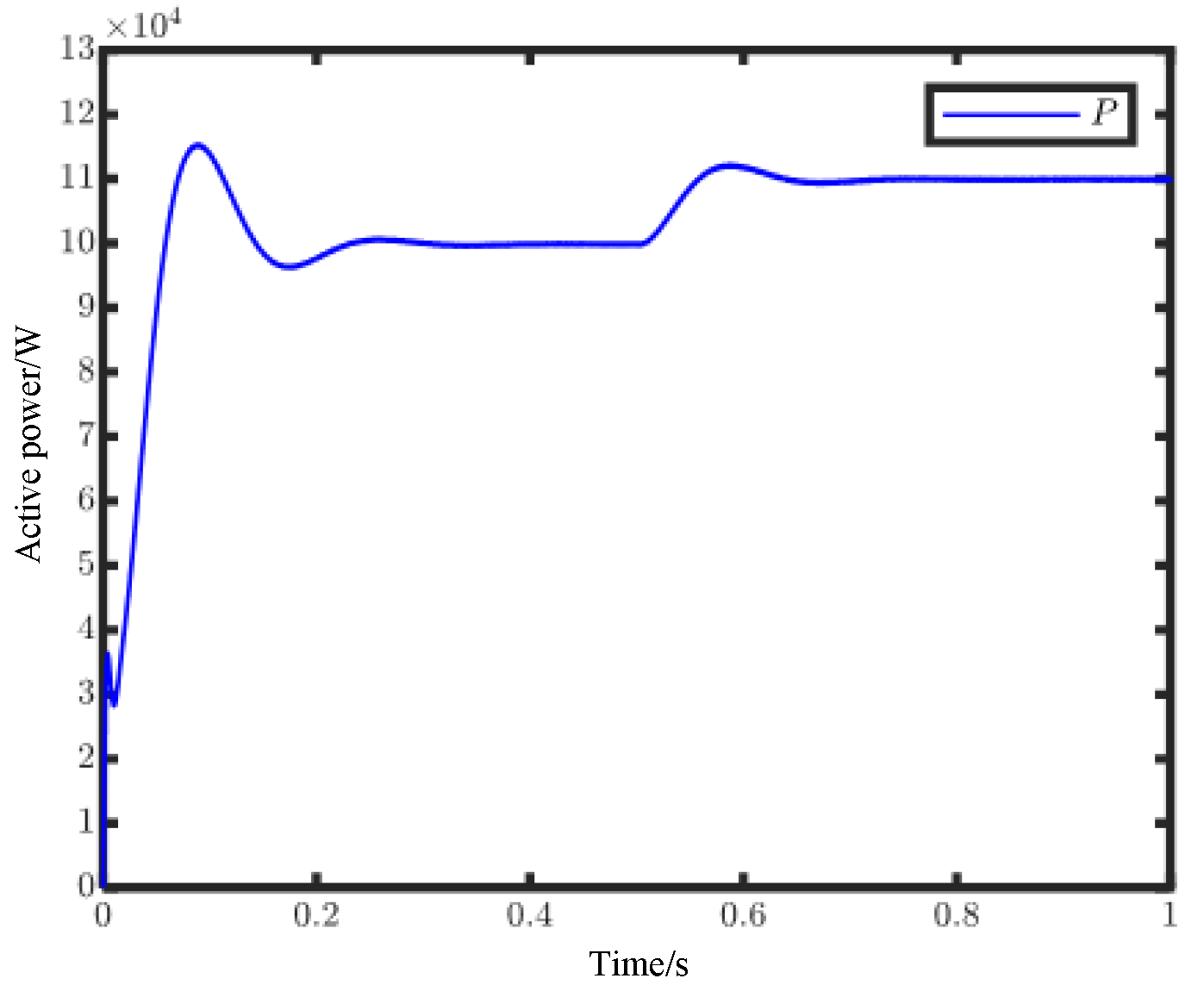
Figure 16 show the current transitions from the original steady state to the new steady state when the output active power is increased.
Figure 16 shows that after about 0.2 s, the peak current is stable at 235.7 A, and the steady output power achieves 110 kW at 0.7 s.
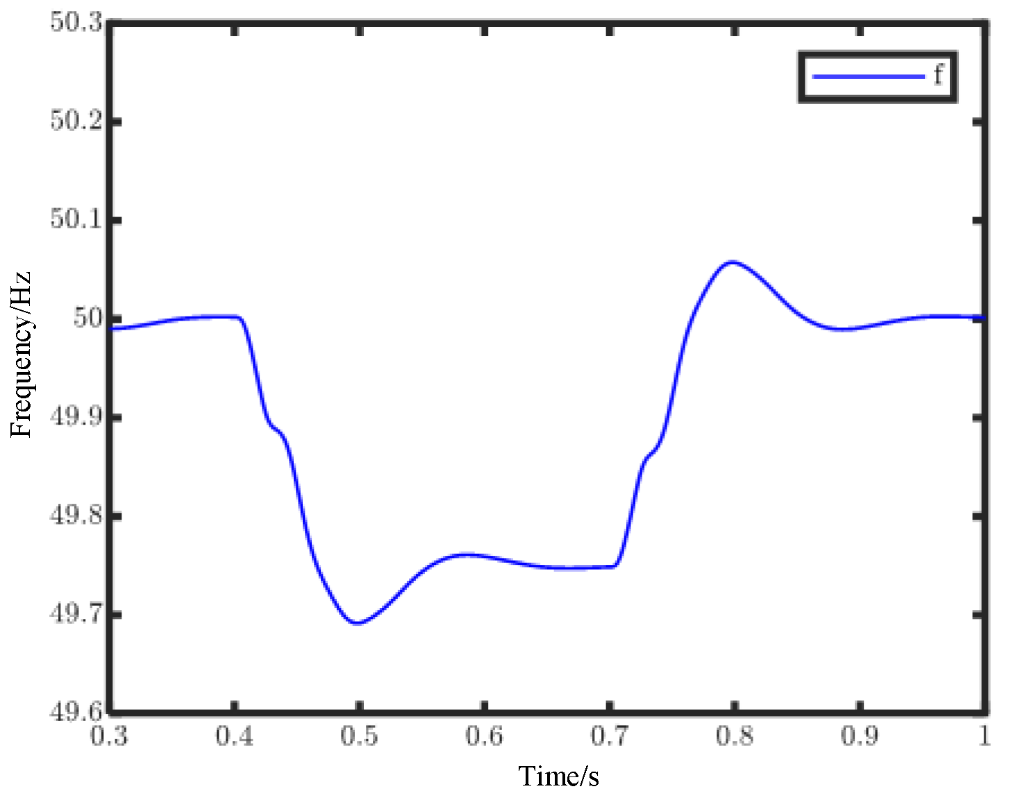
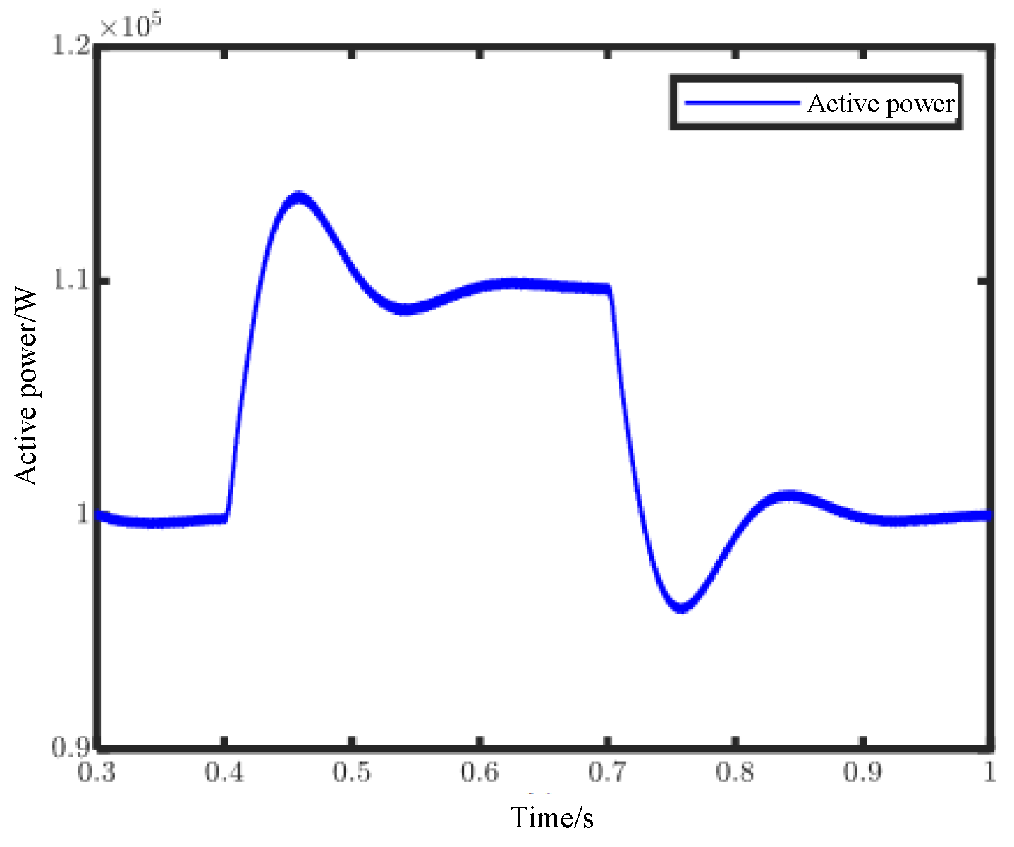
The frequency regulation performance of the multilevel inverter under grid-connected state control by VSG is shown in
Figure 17 and
Figure 18. As the frequency of the power grid decreases by 0.25 Hz from 50 Hz at 0.4 s and restores to 50 Hz at 0.7 s,
Figure 16 shows that due to the decrease in the grid frequency at 0.4 s, the multilevel inverter will increase the active power to reduce the decrease in system frequency as the primary frequency modulation. Additionally, the active power is emitted to the original power when the system frequency is restored to 50 Hz. During the whole process of primary frequency modulation, the output frequency of a multilevel inverter system remains basically unchanged.
- (3)
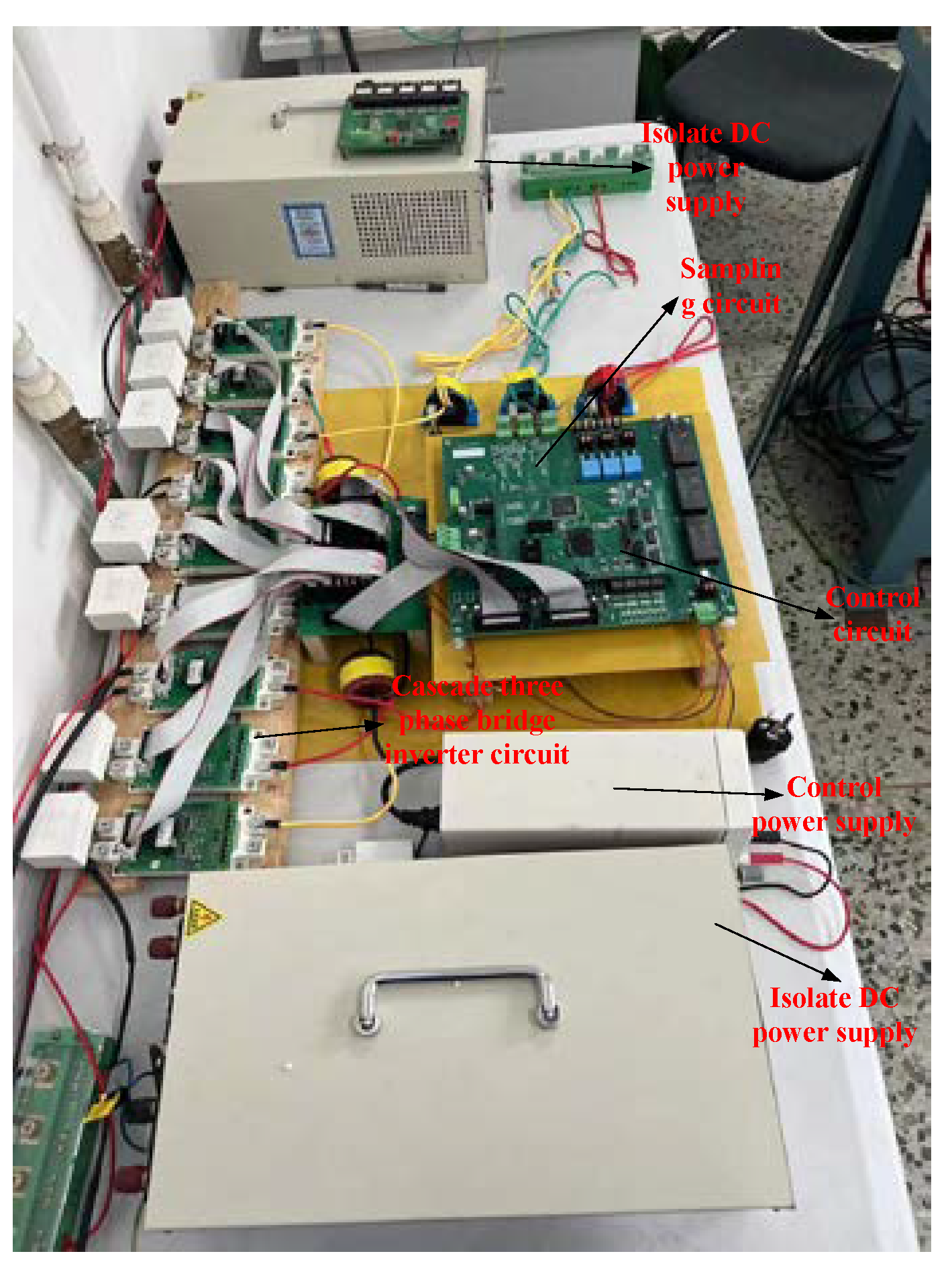
Experimental results
This paper builds an experimental platform of cascading three-phase bridge inverters based on the VSG control strategy, which is shown in
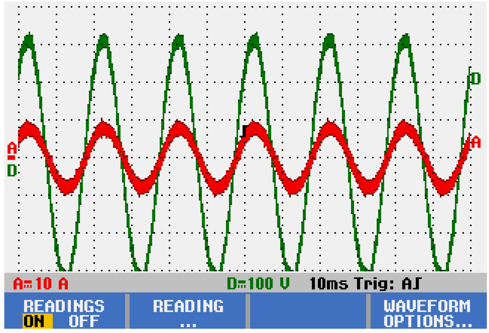
Figure 19. The VSG controller is mainly composed of a control circuit and a sampling circuit. The VSG control strategy and CPSD-PWM strategy are implemented by the DSP and FPGA dual chips in the control circuit, as are the current hall sensors, voltage sensors, and DC-DC source. Due to limited laboratory equipment, this paper adopted a miniaturized experiment to verify the proposed CPSD-PWM control strategy and VSP control strategy. The 20 Ω resistance is selected as the experimental load, and three 100 V isolation voltage sources are used as the DC bus voltage of the submodule. The experimental results of a cascaded three-phase bridge inverter in island mode are shown in
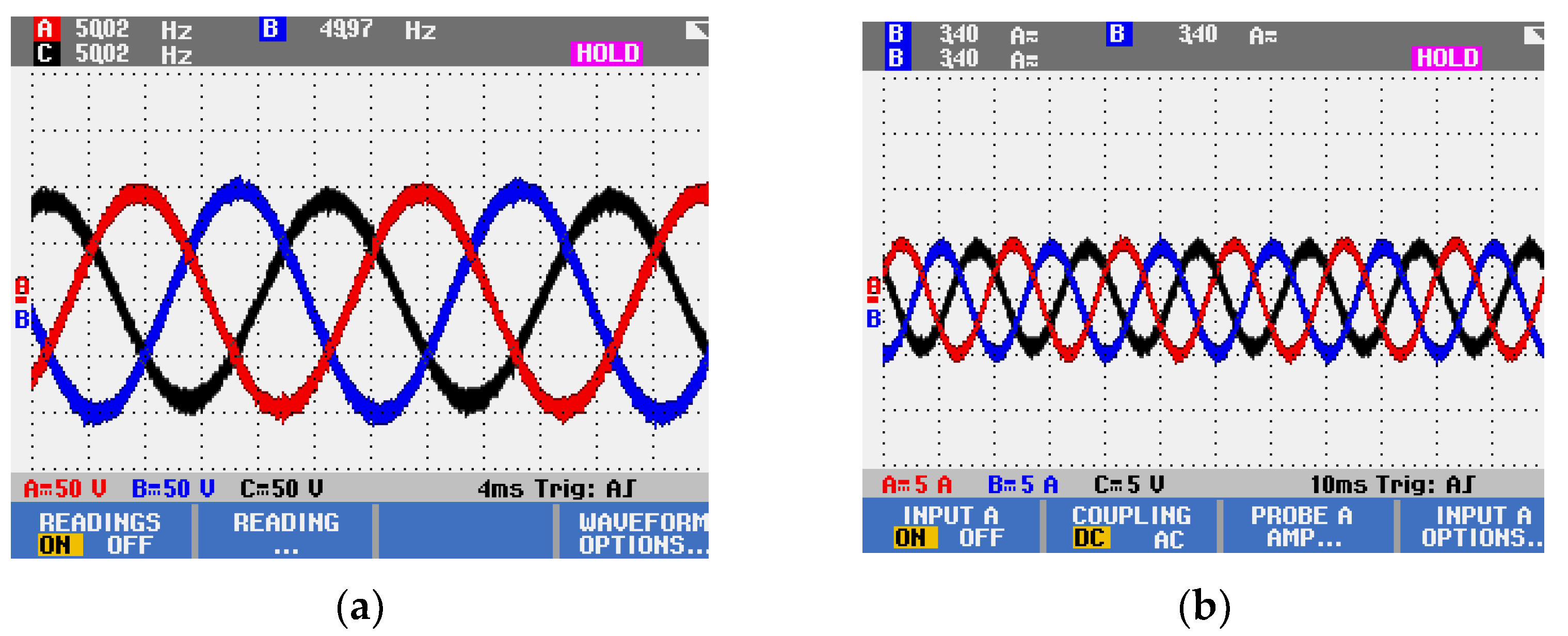
Figure 20. The initial load is 20 Ω, and after a period of time, the switching load condition of twenty ohms is simulated.
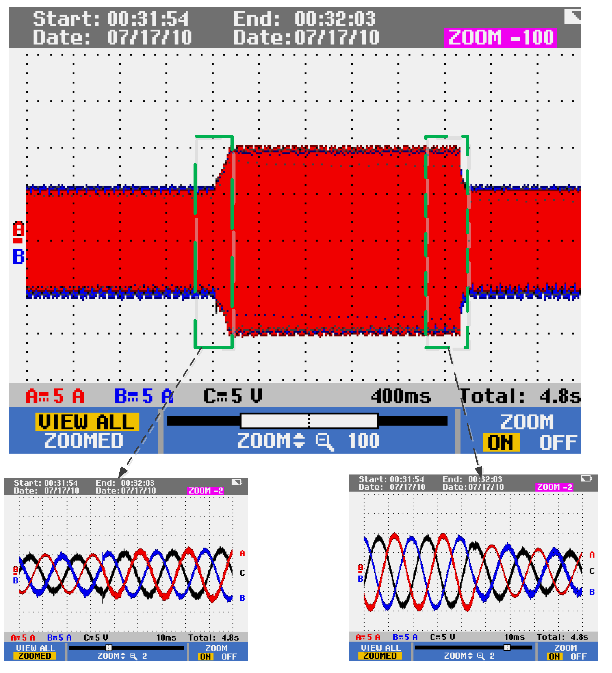
Figure 20 shows that before the load change, the inverter output voltage and current were symmetric three-phase sinusoidal signals. Additionally, when the load is changing, the current and voltage of the cascaded inverter are shown in
Figure 21 and
Figure 22.
Figure 21 and
Figure 22 show that the output voltage and current of the cascaded inverter only mutate slightly after the load is switched and quickly stabilize to the new state after a short time. In addition, the three-phase voltage only has a slight mutation when the load is removed, and after a period of time, it returns to its original stable state. Three-phase current RMS is about 3.5 A, three-phase voltage RMS is 71.7 V, and the three-phase current voltage waveform is smooth without distortion.
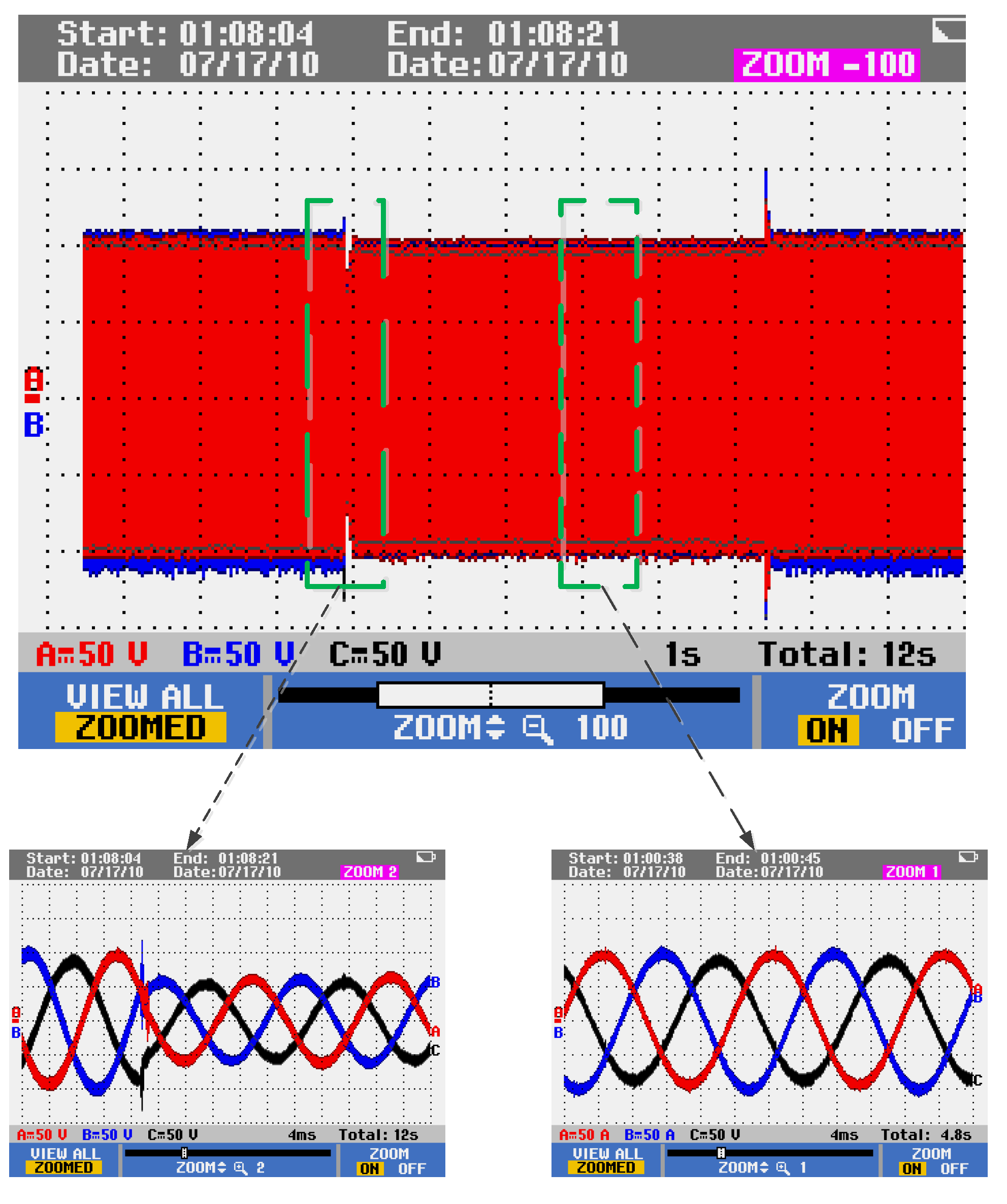
In addition, it can be seen from
Figure 21 and
Figure 22 that the output voltage of the cascaded three-phase bridge multilevel inverter will undergo a short, sudden change when the load is put in, then quickly return to the original stable state after a short time and remain unchanged. The moment the load is removed again, the three-phase voltage has a slight mutation, and it recovers after a period of time. The peak voltage impulse of the cascaded three-phase bridge inverter system based on the VSG control strategy is about 125 V when the load is put in, while the voltage impulse of the traditional two-loop control method is about 175 V. Compared with the conventional system, the proposed cascade inverter system has a small voltage impulse fluctuation and rapid dynamic response and can quickly achieve the expected effect with a small fluctuation. When the load is removed, the former also quickly returns to a stable state with small voltage fluctuations.
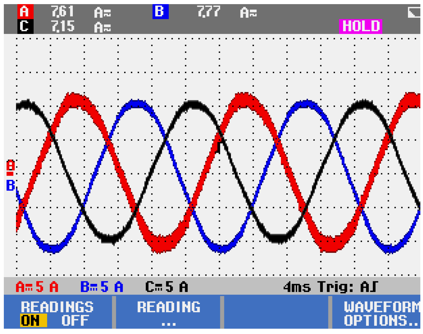
The experimental results of a cascaded three-phase bridge inverter in grid-connected mode are shown in
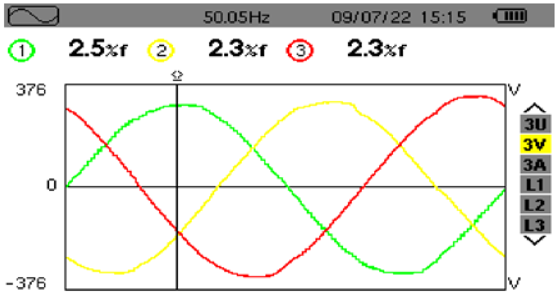
Figure 22. The voltage of the isolated DC bus source for each submodule is set to 200 V, the reference active power is 500 W, and the reference reactive power is 0 kvar.
Figure 23 shows that the output current of the cascaded inverter in the grid-connected mode is symmetric three-phase current, and it can be seen from
Figure 24 that the output current in any phase of the three-phase inverter and the voltage of the corresponding phase are kept in the same phase, so that the power factor is maintained at 1.
Due to the limited experimental equipment, the voltage of the power grid is introduced into the system through the three-phase voltage regulator. Therefore, the RMS values of the three-phase voltage are not the same, caused by the asymmetry in the grid voltage and voltage regulator, which will introduce some errors into the experimental results. Although the experimental conditions are unfavorable, the THD of grid-connected voltage is still only about 2.5% and less than 5% to meet the grid-connected requirements. which is shown in
Figure 25. However, the harmonic distortion rate of the output voltage within the traditional double closed-loop control will reach about 3.9%. Although it is still less than 5%, which can meet the needs of the grid-connected operation, more harmonics will cause more loss and affect microgrid stability. Therefore, compared with traditional control methods, the cascaded three-phase bridge inverter system based on VSG control and CPSD-PWM control strategies can effectively reduce the THD of inverter output and improve power quality.
5. Conclusions
Aiming at improving the multilevel inverter operation characteristics, this paper proposes a cascaded three-phase bridge inverter topology that can improve the balance of three-phase output compared with the traditional cascaded H-bridge inverter. The mathematical model of a three-phase cascaded bridge inverter is built in this paper to analyze the relationship between voltage, current, and power. Based on the inverter model, a new modulation strategy named CPSD-PWM is proposed in this paper, which is more suitable for cascaded three-phase bridge inverters. The analytical expression of the output voltage harmonic spectrum of CPSD-PWM is derived by dual Fourier analysis. Compared with the traditional modulation strategy, the proposed CPSD-PWM can reduce the harmonics and significantly improve the three-phase output balance of the cascaded three-phase bridge inverter, through which the multilevel realizes the three-phase adaptive balance. In addition, this paper studies the cascaded multilevel power generation system based on VSG control. According to the work needs of the cascaded three-phase bridge inverter applied in microgrid operation in isolated island and grid-connected operation, the output frequency and voltage of the inverter can be accurately controlled through active power-frequency control and reactive power-regulating control. This paper optimally designs the virtual inertia and virtual damping to improve the stability of frequency regulation so that the multilevel cascaded inverter by VSG control applied in the microgrid can realize the primary frequency modulation and primary voltage regulation and effectively improve the operation stability in the island model and grid-connected model. This paper builds the experimental platform of a cascaded three-phase bridge inverter, and the simulation and experimental results verify that the cascaded three-phase bridge inverter system based on the CPSD-PWM modulation strategy and VSG control strategy can achieve effective and accurate control of the output voltage and frequency in the power system.
Although the PWM modulation strategy and the grid-connected control strategy based on a virtual synchronizer proposed in this paper can effectively improve the stability of the new energy power generation system, there are still some shortcomings. Since the cascaded three-phase bridge inverter system adopts the direct grid-connection form to eliminate the transformer, there is parasitic capacitance between the grid-connected system and the earth, and the grid-connected filter element forms a common mode resonance loop with the grid impedance, by which the common mode voltage generated by the CPSD-PWM method will generate common mode current in the microgrid system. Common mode current will increase the harmonics, reduce the quality of grid-connected current, and cause serious EMI noise, which will bring great potential hazards and stability problems to the microgrid system. Therefore, in future research, further optimization and improvement of the CPSD-PWM strategy will be studied to reduce the output common-mode voltage component of the inverter system and improve the operation reliability of the microgrid system. The cascaded three-phase bridge grid-connected system proposed in this paper based on the VSG control strategy can obtain good quality inverter output and fast and smooth network access. However, its parameter design is difficult, and it is relatively easy to be affected by system parameters and external interference, which may easily cause unstable system operation and complicated control parameter design under complex working conditions. In the next phase of research, it is necessary to further improve and optimize the VSG control strategy for the cascaded three-phase bridge inverter system to comprehensively improve the system response speed, robustness, and output voltage waveform quality.


