1. Introduction
With the development of automobile technology, anti-lock braking systems (ABSs) and electronic braking systems (EBSs) have been widely used in various vehicles, which greatly improves the reliability of braking systems. However, these technologies still cannot solve the problems of high-temperature failure of the main brakes and the excessive wear of brake pads. To solve the problem of main brake failure due to high temperature and brake pad wear when heavy vehicles brake continuously on long downhills, many countries have formulated standards to apply a combined braking system on heavy vehicles, which is dominated by friction braking and supplemented by non-contact brake retarders with continuous working ability [
1].
According to different working principles, retarders are mainly divided into engine braking retarders, exhaust braking retarders, hydraulic retarders (HRs), and eddy current retarders (ECRs). Compared with other retarders, ECRs have a simple structure, easy control, and fast response speed [
2,
3,
4]. However, the existing ECRs have a serious heat fading of braking torque during continuous braking due to their air-cooled heat dissipation structures. To solve the above problems, some scholars propose liquid-cooled ECRs [
5,
6,
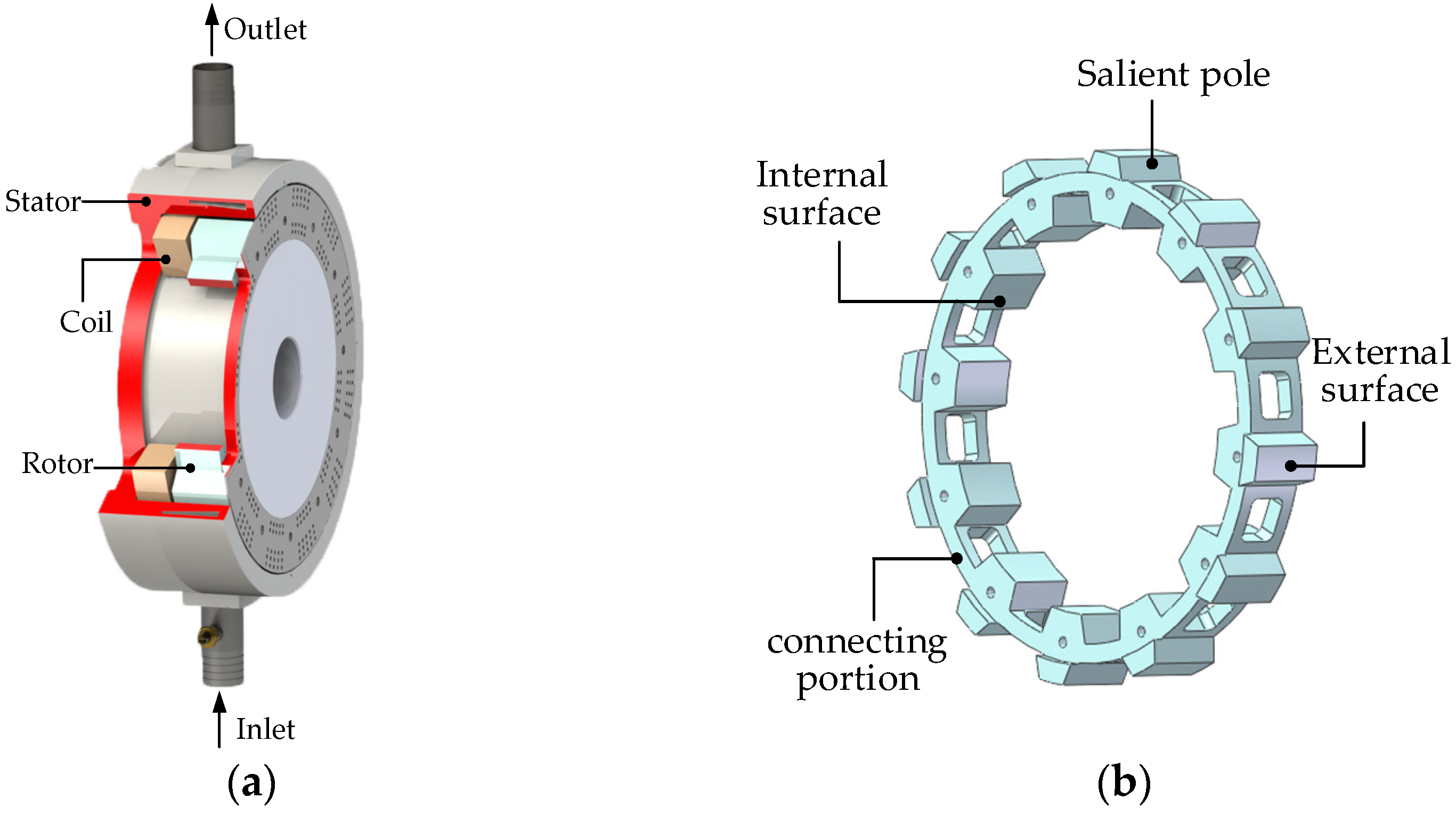
7]. In these liquid-cooled ECRs with different structures, the dual air-gap liquid-cooled eddy current retarder (DAL-ECR) is a good application prospect in industrialization because of its light rotor and high braking power density [
7].
The main methods to predict the braking performance of ECRs are the finite element method (FEM), the analytical method, and the magnetic equivalent circuit method (MEC). The FEM is considered to be an effective method for predicting the braking performance of the ECR [
8,
9,
10,
11], but it is expensive and time-consuming. Therefore, many scholars choose to use Poisson’s and Laplace’s equations to establish the analytical models of the ECRs and to determine the coefficients of the models through the boundary conditions. The MEC is considered as a semianalytical method, which is the idea that the magnetic field is equivalent to the magnetic circuit. Compared with the FEM, the analytical method and the MEC is faster in calculation, but the calculation error is larger. Therefore, the analytical method and the MEC are often used to guidance for the preliminary design of ECRs.
Shin et al. [
12], Lubin et al. [
13], and Gulec et al. [
14] proposed analytical models which considered the actual closed path of eddy currents, respectively, but the models ignored the end effect of the magnetic field and the heat effect on conductivity. Therefore, Jin et al. [
15] and Lubin et al. [
16] proposed 3D analytical models for the end effect of the ECRs, respectively. Jin et al. [
17] and Ye et al. [
18] proposed analytical magnetic–thermal coupling models, respectively, and their computing results agreed well with the measured results. However, the analytical methods neglected saturation of the core, and they are not suitable for the prediction of the performance of the saturation excitation ECRs for heavy vehicles. Hence, the MEC was used for the design of the ECRs by considering the magnetic saturation and electromagnetic characteristics of all materials [
19,
20,
21,
22]. Based on the MEC and the thermal resistance network method, Gulec et al. [
23] proposed a magnetic–thermal coupling model considering the influence of heat on the electromagnetic properties of materials. Kou et al. [
24,
25] studied the electromagnetic performance of ECRs by combining the MEC with the analytical method. Despite the continuous improvement of the ECRs’ calculation models, the problem of the unsteady transient permeability of the eddy current disc at different speeds was rarely considered. The change of the transient permeability is caused by the skin effect of the eddy current disc when the ECR works. The transient permeability will decrease with the increase of the ECR speed under constant excitation current, which is the key factor restricting the increase of the ECR torque at high speed. Although Guo et al. [
26] considered this situation, a permeability distribution model proposed in the paper was obtained by experiments. Hence, the model inevitably increased the cost and time consumption.
Based on the introduction of the structure and working principle of the DAL-ECR, this paper presents a torque model of eddy current braking, which considers the problems of magnetic flux leakage, end effect, and the transient permeability. Based on the skin effect of the eddy current magnetic field, an iterative method is proposed to solve the transient permeability of the stator. The advantages of the transient air-gap flux density model considering transient permeability are verified by FEM. Finally, the eddy current braking torque model was verified by the bench test.
3. Analysis Method
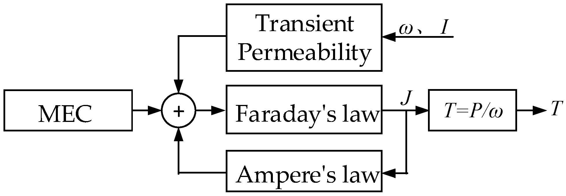
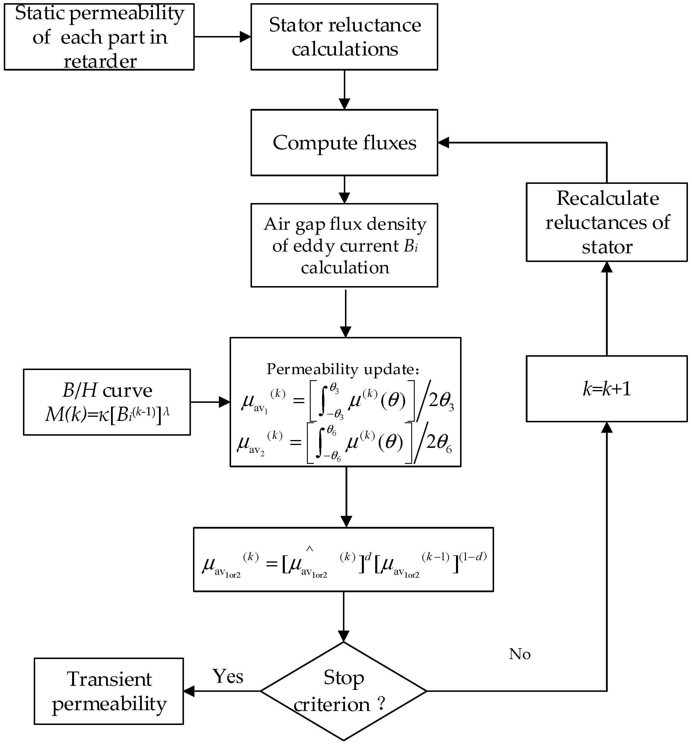
To simply and intuitively show the basic ideas of the calculation model proposed in this paper, this section uses block diagrams to represent each link required for the establishment of the calculation model and uses arrows to indicate the transfer directions of each action, as shown in
Figure 2. The transient permeability given in
Figure 2 refers to the stator permeability of the retarder operating at different speeds and different excitation currents. The transient permeability is introduced into the model to consider the influence of the skin effect on the stator permeability.
The model proposed in this paper is based on the model proposed in the literature [
22], which takes into account the change of transient permeability with the change of current and speed. Firstly, the static air-gap magnetic density distribution is obtained by MEC considering the magnetic field end effect (in
Section 3.1). Secondly, the eddy current density and the transient air-gap flux density distribution are obtained by Faraday’s law and Ampere’s law (in
Section 3.2). Then, the transient permeability is obtained by an iterative method (in
Section 3.4). Finally, the eddy current braking torque is obtained by the relationship between torque, braking power and rotational speed (in
Section 3.5).
3.1. MEC Analysis Model
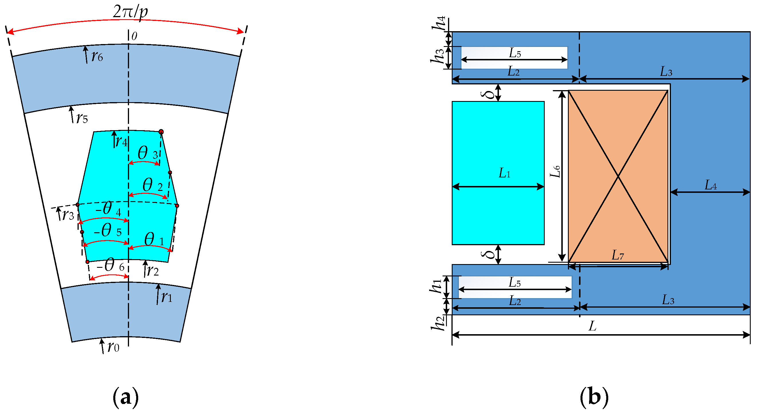
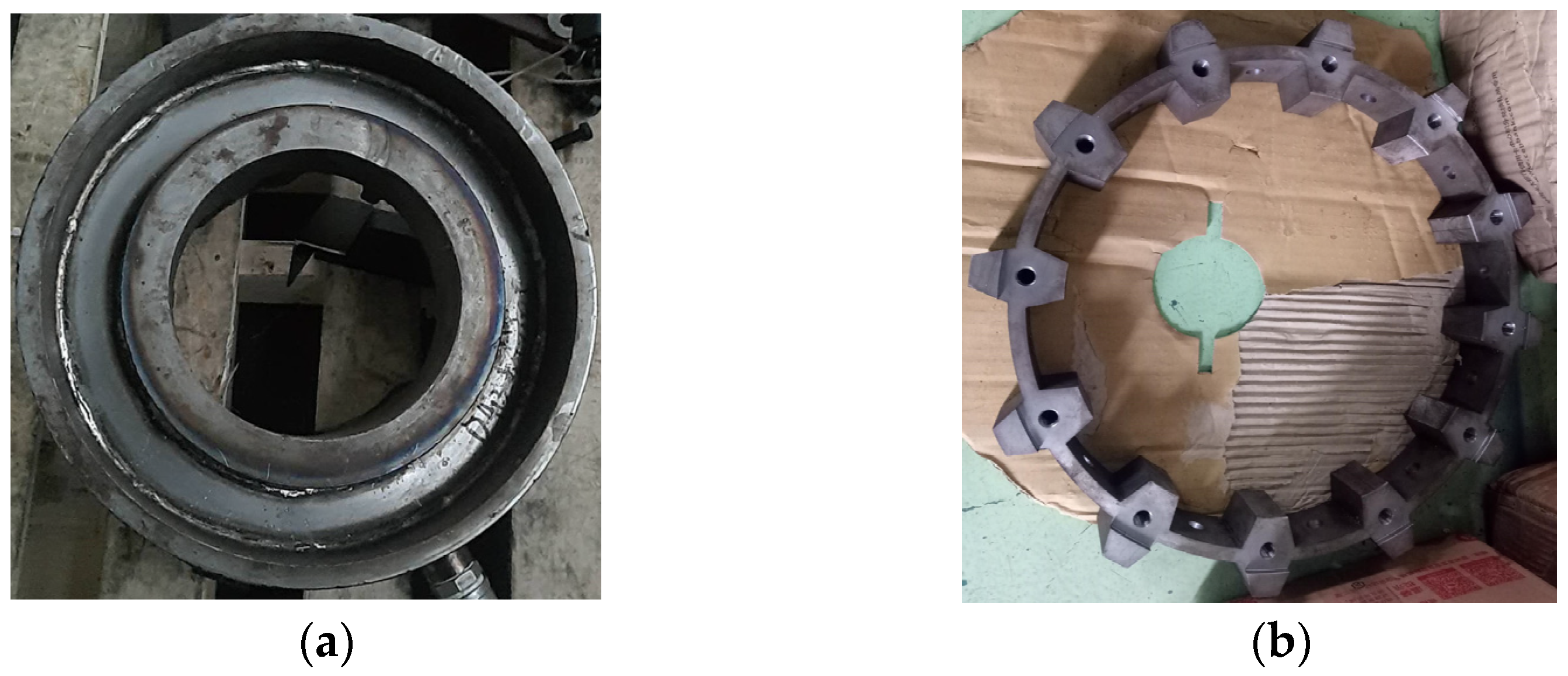
Due to the symmetry of the brake system, the analysis model is 1/12 of the whole actual DAL-ECR, as shown in
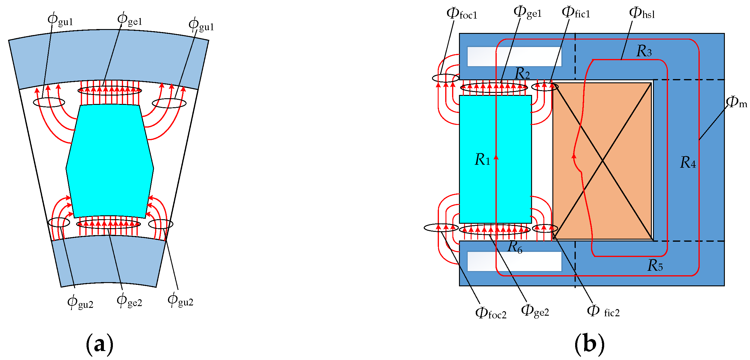
Figure 3. The main magnetic flux and leakage flux formed by the excitation coil are shown in
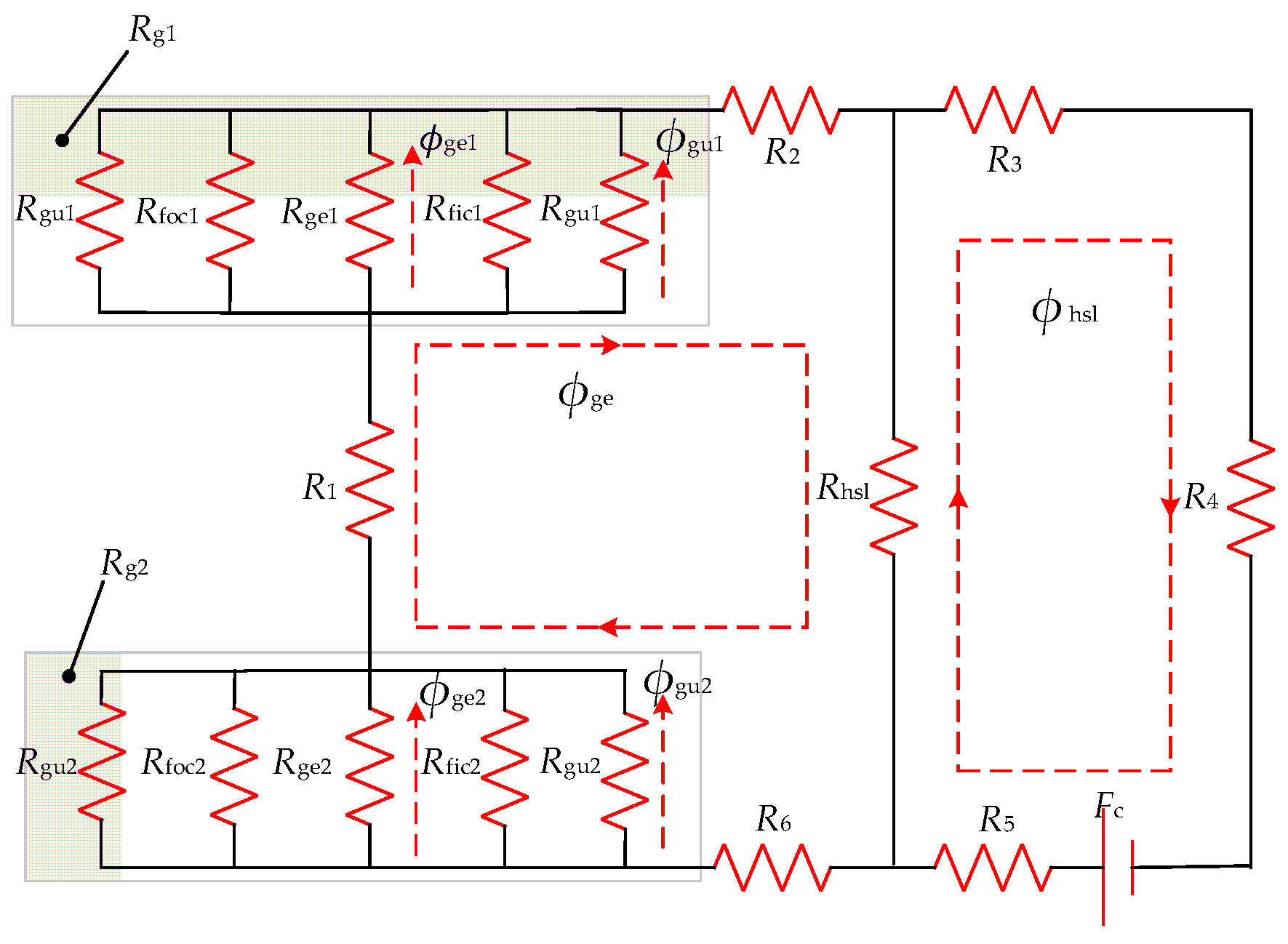
Figure 4. To obtain the air-gap magnetic density of the DAL-ECR, the MEC diagram is established according to the analysis model, as shown in
Figure 5.
The magnetic motive force (MMF) from the excitation coil can be obtained by
where
N is the turn number of the coil and
I is the current in the coil.
According to
Figure 3,
Figure 4 and
Figure 5, each part of the magnetic reluctance of the DAL-ECR can be obtained by the following formulas:
where
p is the number of teeth of the rotor;
μ0 is the air permeability;
μ1,
μ2,
μ3,
μ4,
μ5, and
μ6 are the relative permeability of
R1,
R2,
R3,
R4,
R5, and
R6 shown in
Figure 3. The permeability of each part of the DAL-ECR in the static state can be obtained by an iterative method [
1,
15].
The air-gap magnetic reluctance of each part in the period can be obtained by
The slot leakage flux
ϕhsl is the main part of the leakage flux, as shown in
Figure 4. The magnetic reluctance of the slot leakage flux can be obtained by
According to Kirchhoff’s voltage law, the following formulas can be given:
The static air-gap flux can be expressed as
Under static state, the amplitude of the air-gap flux density of each part can be expressed as
Based on the piecewise function, the upper and lower static air-gap magnetic flux densities in one period can be expressed as
where
α1,
α2,
α3, and
α4 are coefficients.
3.2. Armature Reaction
When the DAL-ECR is braking, the rotating magnetic field induces the eddy current in the stator. The induced eddy current density in upper and lower surfaces in the stator slot are as follows:
where
σ,
ω,
Bδ1(
θ), and
Bδ2(
θ) are the conductivity of the stator, the angular velocity, and the upper and the lower total air-gap flux density.
The MMF generated by the eddy current will affect the size and distribution of the original air-gap magnetic field generated by the excitation coil. Therefore, the upper and the lower total air-gap flux density are obtained as follows:
where
B1(
θ),
B2(
θ),
Bi1(
θ), and
Bi2(
θ) are the upper air-gap flux density by the excitation coil, the lower air-gap flux density by the excitation coil, the upper air-gap flux density by the eddy current, and the lower air-gap flux density by the eddy current, respectively.
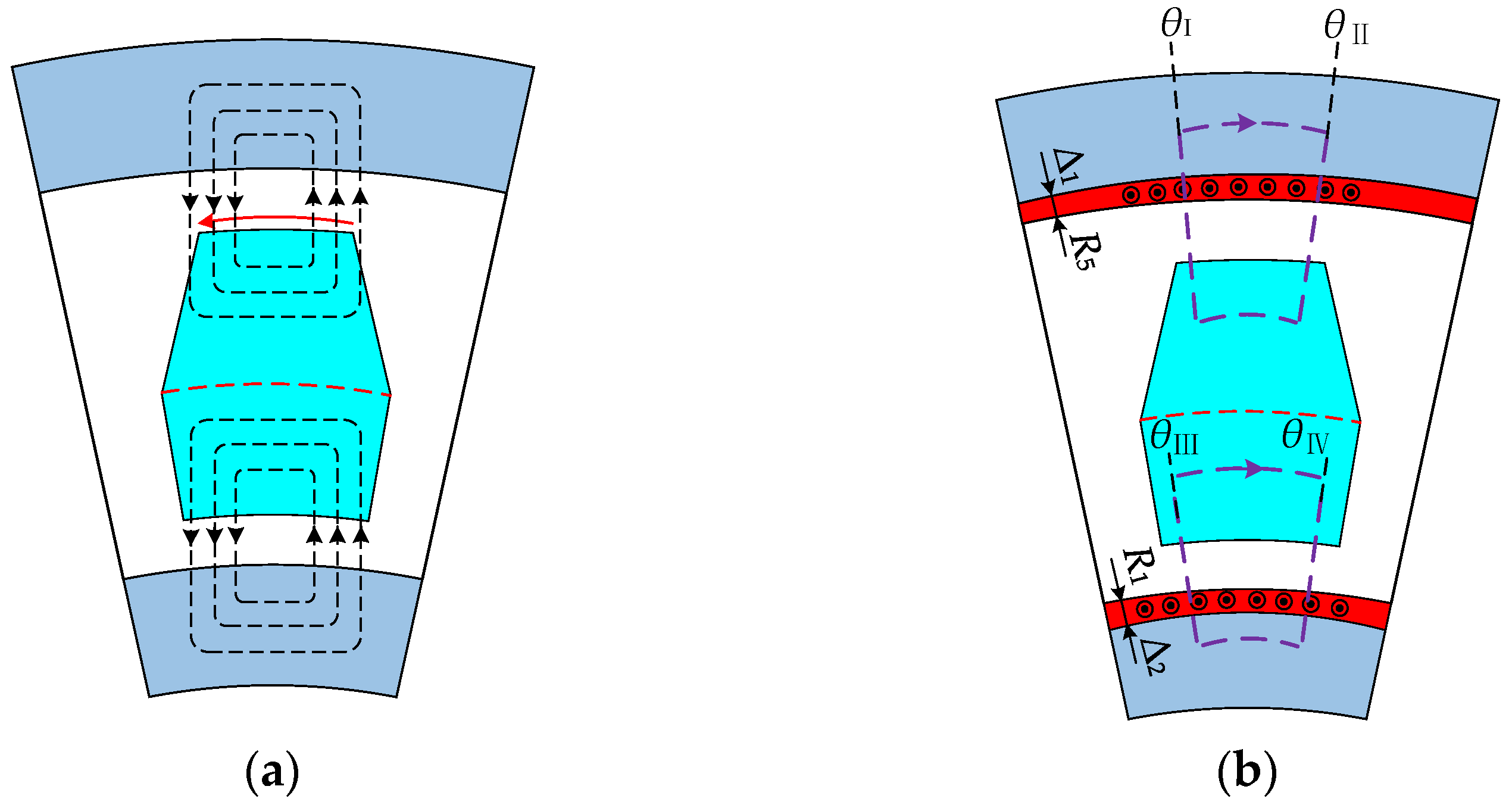
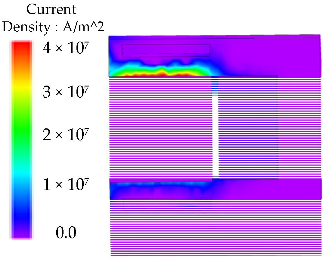
Figure 6a shows the effective reaction flux lines. The FEM shows that the eddy current is concentrated in a small depth near the air gap under transient condition, as shown in
Figure 7. Therefore, as shown in
Figure 6b, the MMF generated in the region of the eddy current density in upper and lower surfaces in the stator slot can be given by
where
c1 is the integral loop of the magnetic field intensity in the upper part of the stator,
c2 is the integral loop of the magnetic field intensity in the lower part of the stator as shown in
Figure 6b, Δ
1 is the skin depth of the upper part of stator in transient state, and Δ
2 is the skin depth of the lower part of stator in transient state.
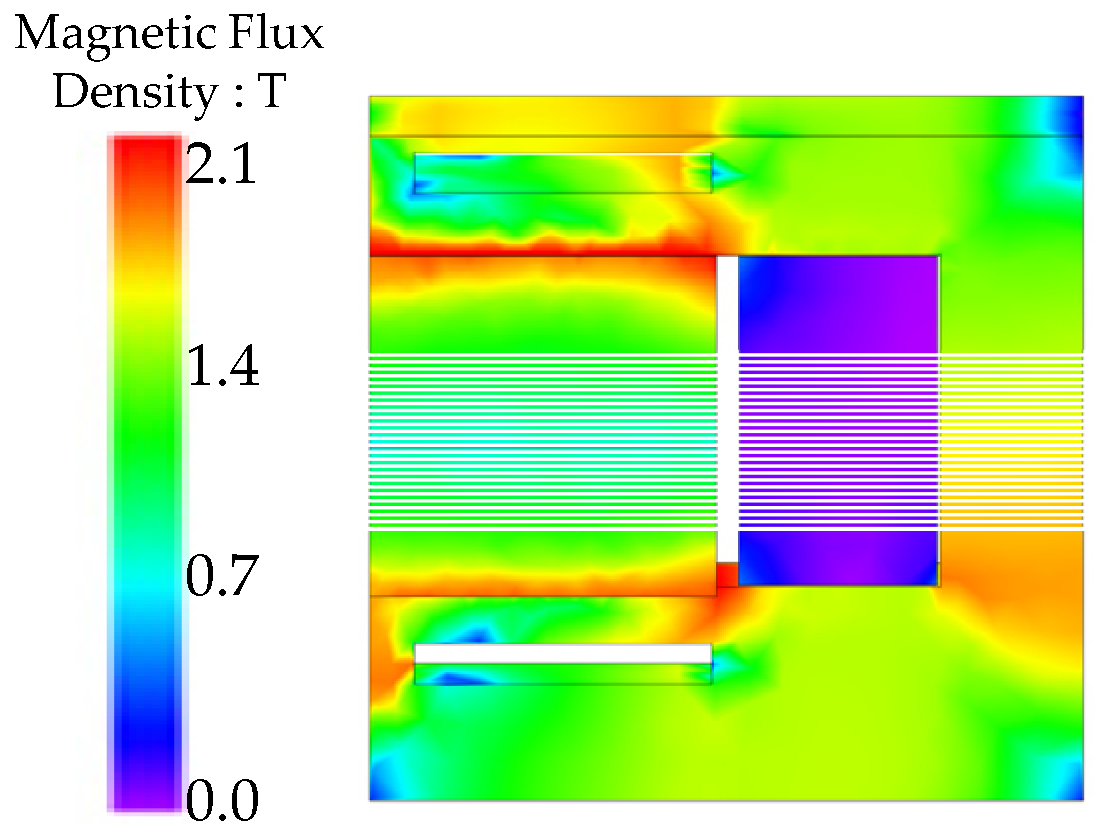
Figure 8 shows that the magnetic field is concentrated in a small skin depth. The skin depth can be given by
The permeability of the stator and the rotor is much higher than those of the air gap. Therefore, the MMF drops across the stator, and the rotor can be ignored. Hence, Equations (36) and (37) can be transformed into:
Taking Equations (32) and (33) into Equations (39) and (40), respectively, the following equations can be given:
Taking the derivative of the Equations (41) and (42) with respect to
θ, the following equations can be obtained:
When ±π/
P <
θ < ±
θ2 and ±π/
P <
θ < ±
θ5, the air gap value is large, and the reaction magnetic field in these regions can be assumed to be 0 T. Hence, Equations (43) and (44) only applicable to −
θ2 <
θ <
θ2 and −
θ5 <
θ <
θ5. Finally, the upper and lower air-gap flux density generated by the eddy current can be given, respectively, by
where,
k1-3,
k1-4,
k1-5,
k2-3,
k2-4, and
k2-
5 are coefficients.
The boundary conditions for solving Equations (45) and (46) are given, respectively:
where
θ0-1 is a special point where the all currents in the upper stator enclosed in the intervals [−π/
p,
θ0-1] and [
θ0-1, π/
p] are equal, and
θ0-2 is a special point where the all currents in the lower stator enclosed in the intervals [−π/
p,
θ0-2] and [
θ0-2, π/
p] are equal.
3.3. 3-D Correction
In fact, the distribution of the eddy current in the stator is very complex. To consider this problem, an effective conductivity value [
14] is introduced that is given by
3.4. Transient Permeability Correction
To consider the transient permeability of the stator, the iterative method of transient permeability is introduced, as shown in
Figure 9.
The iterative flowchart is used to determine the transient permeability. It starts by assigning an initial value to
μ1,
μ2,
μ3,
μ4,
μ5, and
μ6 to determine the static reluctance network and compute the fluxes. The permeabilities of each part of the retarder are solved by the previous iteration method [
1,
15].
The working speed of retarders is often greater than 500 r/min, and skin depth of the stator is very small, which means that the magnetic field intensity value is quite high. However, the magnetic force is not provided by the magnetic field by coil, but by the eddy current in the stator. Therefore, the air-gap flux density of the eddy current is equal to the flux density in the stator [
27].
Next, based on Equations (45) and (46), the air-gap magnetic flux densities are calculated and used as magnetic flux densities in the depth of the skin.
Then, based on the
B/
H curve of the utilized steel and eddy current magnetic field of retarder in operation, new permeabilities can be updated by
where
k refers to the iteration time,
κ is the proportional index (0.255 herein),
λ is the exponential coefficient (−12 herein). Due to magnetic saturation in retarder stator,
κ and
λ were set to 0.255 and −12, respectively, to accurately fit the magnetic saturation section in the
B/
H curve. Since equation is a continuous function, the average permeability in upper and lower surfaces in the stator can be obtained by
The process continues until the following criteria are individually satisfied for the permeabilities of the
R2 and the
R6:
where
d is a damping constant set to 0.1 herein.
3.5. Eddy Current Braking Torque
The eddy current braking torque can be given by
4. FEM Verification
To verify the correctness of the proposed analysis model, the DAL-ECR is simulated by FEM. The main design parameters and material properties of the DAL-ECR are shown in
Table 1 and
Table 2.
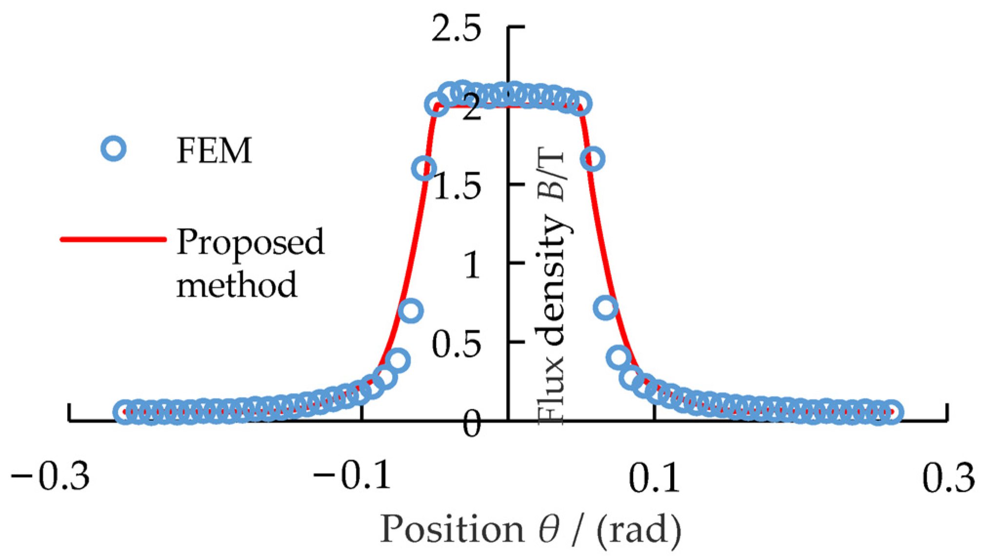
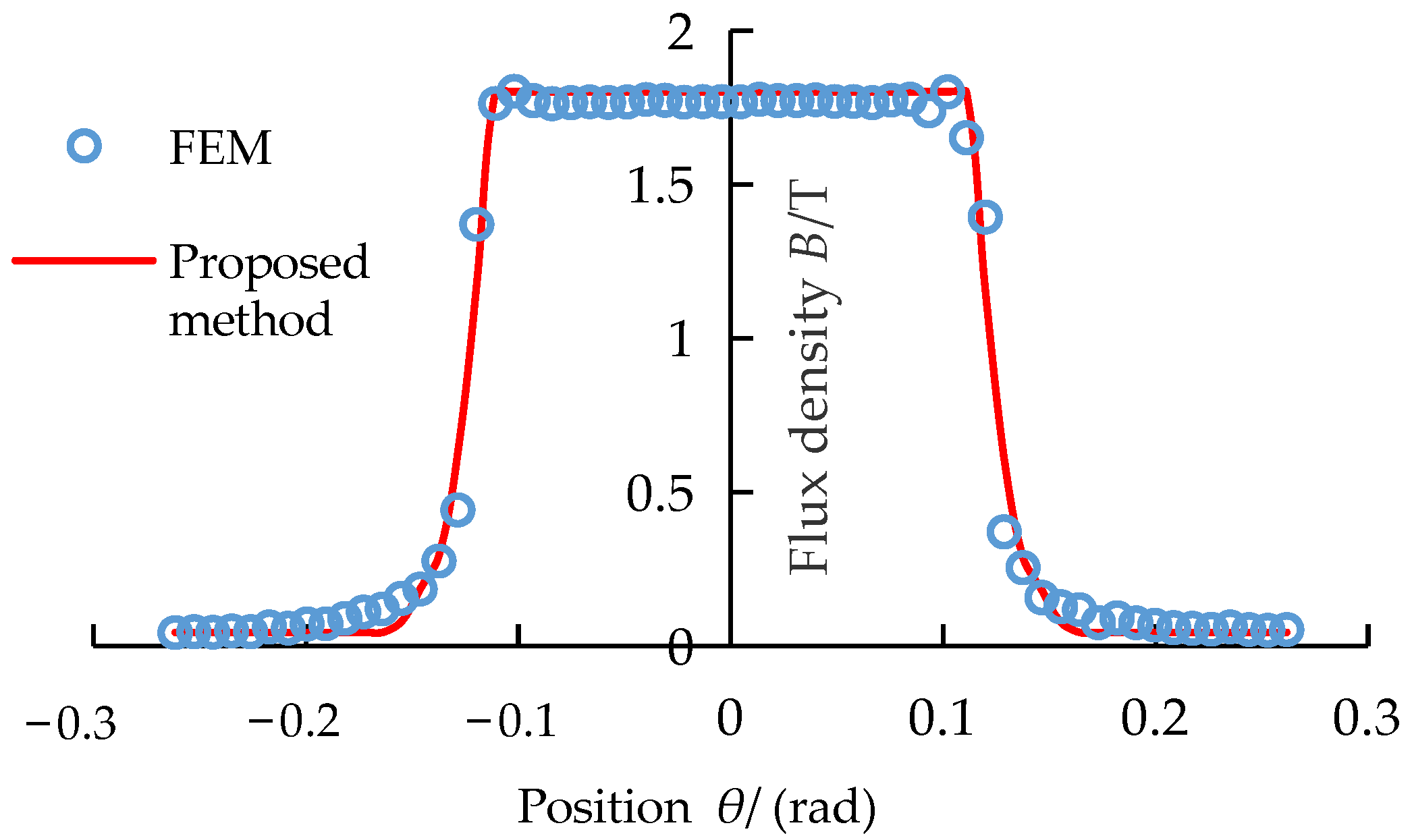
Figure 10 and
Figure 11 show that the static upper and lower air-gap flux density with a current of 80 A predicted by the proposed method are in good agreement with that calculated by the FEM.
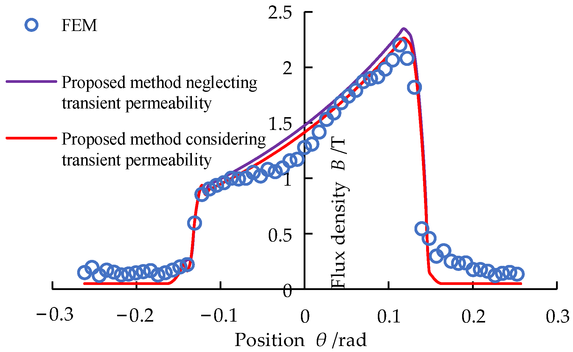
As can be seen from
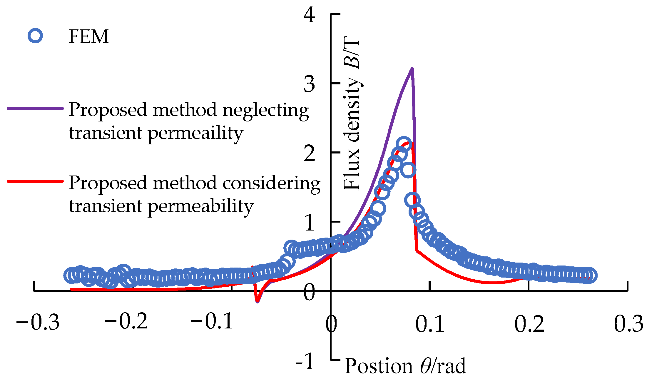
Figure 12, when the excitation current of the coil is 80 A and the rotating speed is 500 r/min, the upper air-gap flux density calculated by the proposed method considering transient permeability is closer to the FEM calculating value than that calculated by the proposed method neglecting transient permeability. Especially in the range from 0.04 to 0.07 rad, the upper air-gap flux density calculated by the proposed method considering transient permeability shows its advantages.
Figure 13 shows that when the speed is 500 r/min and the excitation current is 80 A, the lower air-gap flux density calculated by the proposed method is in good agreement with that calculated by the FEM in the entire region. There is no large error like
Figure 11 in the local area. However, the lower air-gap flux density calculated by the proposed method neglecting transient permeability is higher than that calculated by the FEM and the proposed method considering transient permeability.
As observed from
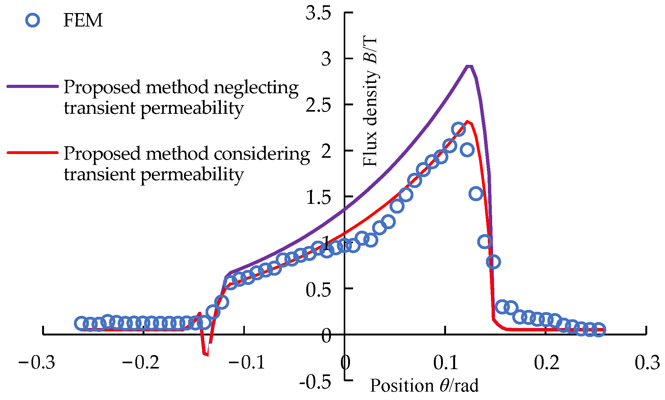
Figure 14, when the speed is 1000 r/min and the excitation current is 80 A, the upper air-gap flux density calculated by the proposed method neglecting transient permeability differs significantly from the FEM value. With the increase of speed, the error of the models increases. However, the error of the mathematical model without considering the transient permeability is larger, especially in the range of from 0.06 to 0.08 rad.
As observed from
Figure 15, when the speed is 1000 r/min and the excitation current is 80 A, the lower air-gap flux density calculated by the proposed method neglecting transient permeability is significantly higher than the FEM and the proposed method considering the transient permeability calculated value. However, the lower air-gap flux density by the model considering transient permeability is in good agreement with the FEM value.
6. Discussion
As observed from
Figure 12,
Figure 13,
Figure 14 and
Figure 15, compared with the upper air-gap flux density calculated by the proposed method, the lower air-gap flux density calculated by the proposed method is in better agreement with the FEM. This is due to the high magnetic saturation in the stator part corresponding to the upper air gap. With the speed increasing, the calculation accuracy of the proposed method becomes worse. This is because the eddy current magnetic field increases with the increase of the speed, resulting in the inconsistent distribution of circumferential permeability on the stator material. However, the proposed model only considers the change of radial permeability with speed and does not consider the change of circumferential permeability distribution with speed.
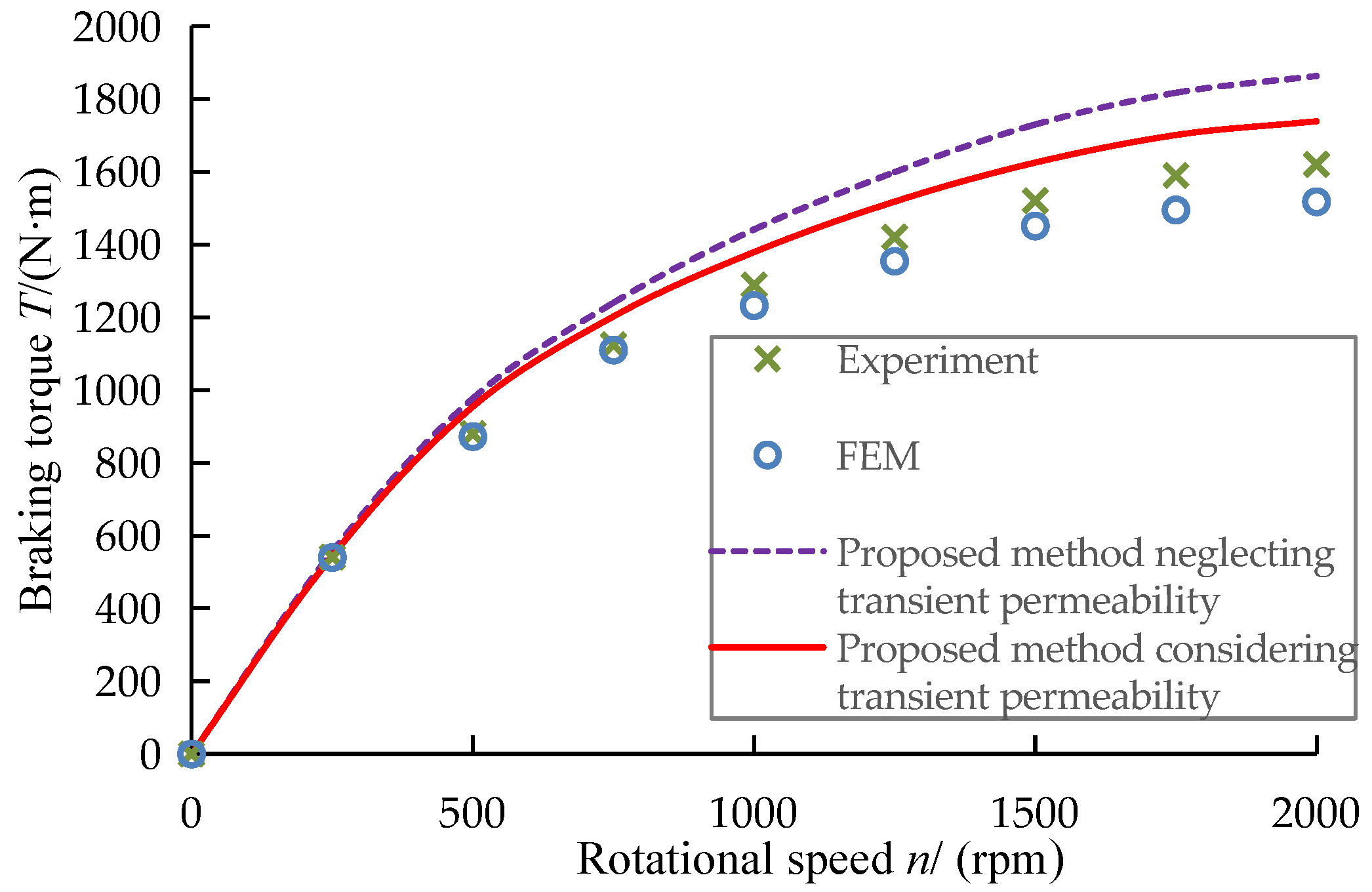
As can be seen from
Figure 21, the braking torque model considering the transient permeability has obvious advantages over the model without considering the transient permeability at high speed. When the retarder is running at high speed, the electromagnetic field in the stator will have a strong skin effect, resulting in a sharp decrease in the permeability of the stator. In this case, even if the speed increases again, the braking torque will not increase significantly. When the speed increases to a certain value, the braking torque will tend to be stable. Therefore, the decrease of permeability caused by the skin effect is an important factor limiting the eddy current braking performance. On the other hand, due to ignoring the influence of heat, the proposed model cannot predict the torque during continuous braking of DAL-ECR.
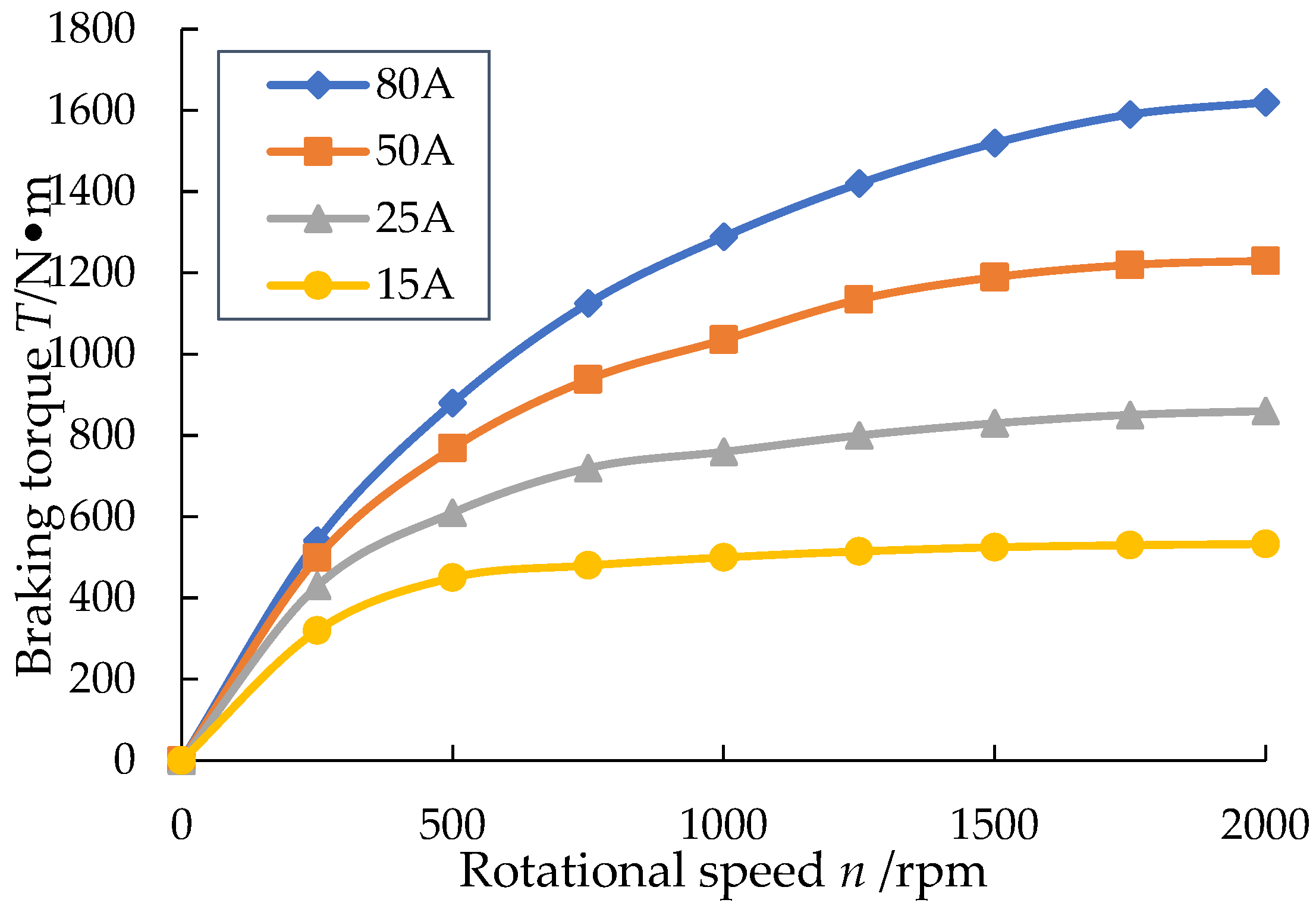
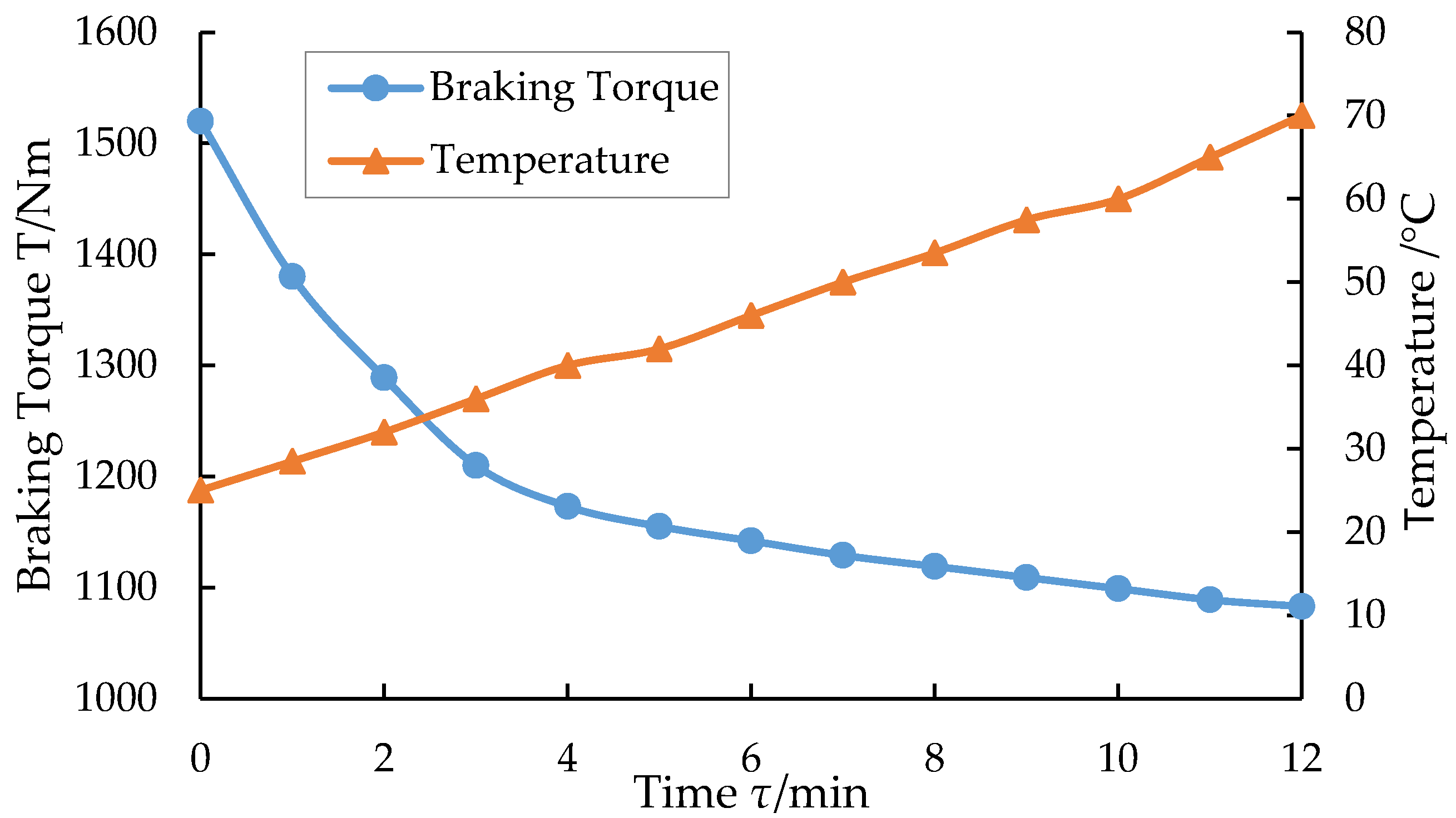
ECRs mainly works in the long downhill continuous braking condition of heavy vehicles, the speed is generally controlled at 35~40 km/h, and the braking torque is not less than 1500 Nm. Therefore, according to the transmission ratio and wheel radius of the heavy vehicles, the working speed range of the ECR can be obtained in the range of 1500~2000 r/min. When the working speed of the DAL-ECR is within the above speed range and the excitation current is 80 A, the braking torque range is 1520~1620 Nm, as shown in
Figure 20. Taking into account the actual capacity of the vehicle battery, the operating current of the ECR generally does not exceed 100 A, so the maximum test current set does not exceed 80 A during the bench test. In addition, the DAL-ECR uses an independent water tank to dissipate heat, and the coolant temperature is controlled at 20–70 °C. The cooling system of the liquid-cooled ECR can also be connected with the cooling system of the engine, so to achieve common heat dissipation of the two, this cooling method will make the coolant temperature control at 80–98 °C. Compared with the independent cooling method, this cooling method will make the brake torque of the retarder smaller.
7. Conclusions
This paper proposed a fast prediction model of the braking performance of the DAL-ECR considering the flux leakage, end effect, and transient permeability, and the calculation accuracy of the model was verified by the FEM and the bench test. The model has no obvious advantage at low speed. However, with the increase of speed, the advantages of the model are gradually obvious.
The proposed method is suitable for the prediction of air-gap flux density with over saturation of excitation and is only suitable for the prediction of eddy current braking of liquid-cooled ECR. Hence, the method has some limitations.


