1. Introduction
The fuel cell (FC) is considered to be an alternative to traditional fossil energy sources such as coal and petroleum in the 21st century. The FC provides an effective approach to solve the shortage of petroleum energy and environmental pollution and is also related to future energy security and long-term development. According to the different electrolytes, fuel cells can be divided into alkaline fuel cell (AFC), phosphoric acid fuel cell (PAFC), molten carbonate fuel cell (MCFC), solid oxide fuel cell (SOFC), and proton exchange membrane fuel cell (PEMFC). Among them, the PEMFC is the most widely used.
Compared with fossil energy sources, the PEMFC technology has the following advantages [
1]: high energy conversion efficiency, with an expected efficiency of more than 80% [
2]; low or even no emissions can be achieved; low noise, high reliability and easy maintenance during operation; and the power generation efficiency is less affected by the load. Therefore, the PEMFC is widely used in many fields such as aerospace, military, electric vehicle, and distributed electricity applications [
3]. However, fuel cells also have many shortcomings: the fuel cell reaction requires the action of catalysts and has high requirements for catalysts; the use of hydrogen energy as fuel, the storage and transportation of hydrogen energy have safety and stability problems; the output characteristics are soft and need to improve the control performance, reduce the impact on the battery due to load changes and the external environment, and improve the battery life [
4,
5].
The safe and efficient operation of the fuel cell cannot be achieved without the operation of its auxiliary system. The auxiliary system regulates the inlet, exhaust, temperature, and humidity of the stack in real-time according to the load demand power to ensure that the stack always operates under the ideal working environment. A complete fuel cell system (FCS) includes a fuel cell stack, gas supply system, temperature control system, humidity control system and energy management system. Among them, the gas supply system includes oxygen supply and hydrogen supply to provide reactants for the electrochemical reaction of the fuel cell, which is converted into electricity through the electrochemical reaction. At the same time, the degree of oxygen and hydrogen supply in the fuel cell largely affects the output power of the fuel cell [
6]. Therefore, effective control of gases in fuel cells is necessary.
The oxygen supply to the fuel cell is provided by an air compressor that pressurizes the outside air and feeds it to the stack. Due to the high latency of air compressors and other equipment, under- or over-supply of oxygen may occur during load current changes. Insufficient oxygen supply can lead to a decrease in output voltage and power, permanently damaging the fuel cell; excessive oxygen supply can lead to an increase in parasitic power, reducing the net system output power [
7]. Therefore, the oxygen flow rate needs to be controlled to ensure the safe and efficient operation of the FCS. In many studies, oxygen excess ratio (OER) is commonly used to measure the degree of oxygen quantity availability, as defined in Equation (
5).
The control core of the air supply system is the regulation of the flow of air into the power stack. The main current air system control strategies are classified according to the control methods: traditional control, advanced control, and intelligent control algorithms.
Traditional control strategies mainly include feed-forward control and PID control. Feed-forward control establishes the corresponding logic control strategy through off-line testing and empirical knowledge, which has the advantages of simple design and small calculation, but the control effect is single and relatively poor. PID methods are widely used in industrial process control because of their simple structure and high reliability, but they are prone to overshoot and jitter in some cases. In Ref. [
8], feed-forward control and PID control were used for PEMFCs, and the coordinated operation of different control methods was simulated to verify the feasibility of the control strategy. Meanwhile, in order to improve the control accuracy and robustness of traditional PID, researchers have successively proposed many improved PID algorithms, such as fuzzy PID and adaptive PID [
9]. Ref. [
10] uses an adaptive fuzzy PID control method to control the gas supply system, which ensures a stable variation of the gas supply system with the change of load power demand and prevents the instability that may be brought by the gas supply system.
For the nonlinear and time-varying characteristics of the PEMFC gas supply system, advanced control strategies such as adaptive control, robust control, and predictive control have achieved good results. E. S. Kim [
11] designed a suitable state feedback controller to improve the response speed and immunity to disturbances of the PEMFC gas supply system. In Ref. [
12], a fuzzy generalized predictive controller based on a control-oriented T-S model is designed to control the oxygen excess ratio in the ideal range and effectively suppress the fluctuation caused by the load change.
Intelligent control mainly uses intelligent algorithms such as neural networks, which have strong robustness and self-learning capability in OER control. M Sedighizadeh [
13] proposed an adaptive control strategy based on artificial neural networks to control the PEMFC system to improve the dynamic performance of oxygen flow control. ChunHua Li [
14] used a fuzzy adaptive recurrent neural network to model the PEMFC air supply system to prevent the occurrence of oxygen scarcity and improve the system response performance. However, the establishment of neural network models requires a large amount of data support and too much computational effort.
The structures of hydrogen supply systems can be generally classified as anode blind-end type and cyclic type. Studies have shown that the cyclic anode structure has a higher system and stack efficiency when the power is above a certain threshold [
15], which has been widely used in recent years. In a circulating hydrogen supply system, the supply of hydrogen is performed by a hydrogen tank, which uses a proportional valve to achieve hydrogen injection and a circulation structure such as a circulation pump to achieve hydrogen recycling. Similar to the OER, the hydrogen excess ratio (HER) has been used to measure the effect of hydrogen flow control, which is defined in Equation (
4).
An adequate and effective supply of hydrogen can be ensured by controlling the circulation flow of hydrogen to ensure the effective operation of the electrochemical reaction while improving the utilization of hydrogen and economic efficiency [
15]. The structure of the hydrogen circuit supply system is relatively simple, and its common control algorithms, including traditional control and predictive control methods, are able to control the inflow and outflow of the hydrogen circuit well. In Ref. [
16], the fuel cell hydrogen gas pressure and HER were controlled by a classical proportional-integral differential controller and a state feedback controller, with good tracking and interference resistance results. In Ref. [
17], a Markov chain and model predictive control (MPC) method was used to control the fuel cell anode supply system, which further improved the dynamic performance of the anode gas supply system response. Yao Wang [
18] designed an adaptive backpropulsion sliding mode (ABSM) controller to control the output mass flow rate of a hydrogen circulation pump, and tested the effectiveness of the ABSM controller by establishing a nonlinear model of the hydrogen supply system and using vehicle driving cycle data from WVUSUB.
Based on the above discussion, this paper adopts a new control method to solve the air and hydrogen flow control problem of FCS. The proposed method has the advantages of enhanced dynamic response performance and stability performance, thereby improving the output performance and economic benefit of the system. The main contributions of this paper are as follows.
A simplified hybrid model environment of the fuel cell air and hydrogen circuits is built;
An optimal flow control strategy based on net power optimization is proposed;
Deep reinforcement learning controllers based on deterministic policy gradient are proposed to control the oxygen flow and hydrogen flow. The effect of decoupled and coupled controllers is compared;
A controller that integrates fuzzy PID and DRL algorithms is proposed, which has a faster dynamic response than traditional PID and more stable steady-state performance than DRL algorithms.
The structure of this paper is listed as follows:
Section 2 presents the dynamic mathematical model of the fuel cell gas supply system. In
Section 3, the deep reinforcement learning algorithm principle is presented.
Section 4 describes the algorithm of controllers proposed in this paper. Simulation results and performance analysis are shown in
Section 5. Finally, conclusions are given in
Section 6.
2. Fuel Cell Gas Supply System
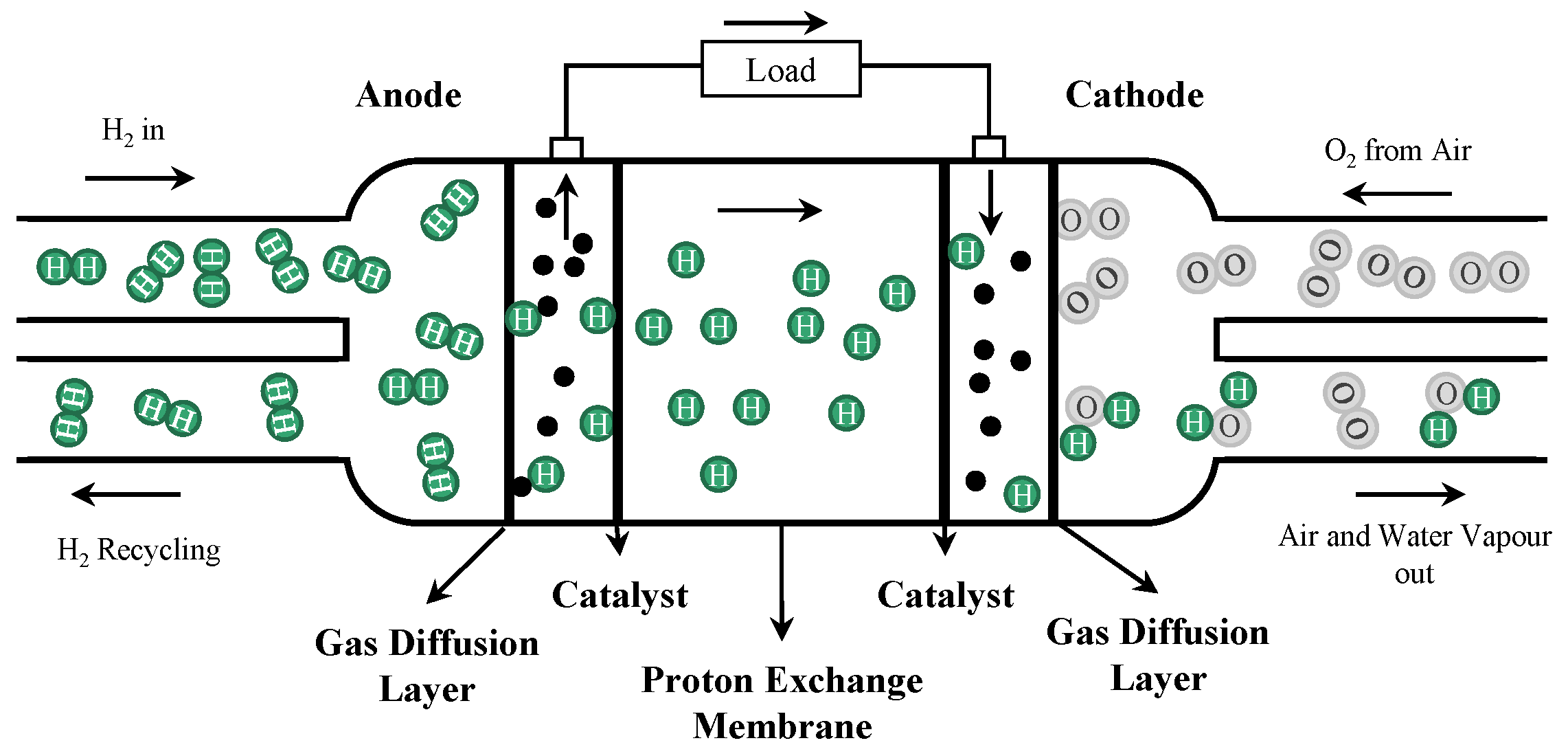
The PEMFC is an electrochemical device that directly converts the chemical energy of gas into electric energy and heat energy by electrochemical reaction. Hydrogen and oxygen (or air) are used as fuel and oxidant of the PEMFC, respectively. Under the action of the proton exchange membrane (PEM) and catalyst, the gases involved in the reaction undergo electrochemical reactions to generate electric energy and heat energy. A schematic diagram of the composition and working principle of a single PEMFC is shown in
Figure 1.
The PEM divides the PEMFC stack into anode and cathode. In the working process of the battery, the hydrogen at the anode loses two electrons under the action of the catalyst and is oxidized into
. The generated
reaches the cathode through the PEM in the form of hydration, and the electrons reach the cathode after working on the load through the external circuit. After oxygen reaches the cathode, under the action of the cathode catalyst, it combines with
and
reaching the cathode to generate water. Therefore, the total reaction process of the PEMFC can be described as:
2.1. Fuel Cell Output Voltage Model
The output voltage model of the fuel cell reflects its electrical output performance. It is a function of the load current, the temperature in the stack, the partial pressure of the reactants, and the relative humidity of the gas. According to the thermodynamic equations in the standard state and the relevant thermodynamic data, the thermodynamic electromotive force of a single fuel cell in the ideal case can be expressed using the Nernst equation as [
19]:
where
and
are the partial pressures of hydrogen and oxygen, respectively, in atm, and
is the battery working temperature in K.
In the working process of the fuel cell, the polarization phenomenon will lead to some inevitable voltage loss, including activation polarization overvoltage
, ohmic overvoltage
, and concentration polarization overvoltage
. The output voltage of a single fuel cell is shown in Equation (
2), which is small. Therefore, multiple fuel cells are often connected in series to form a stack, and the overall output voltage of the fuel cell stack is obtained by Equation (
3).
where
is the voltage at zero current density in V,
i is the current density in A/m
2,
is the limit current density.
,
,
and
are the constants related to the gas pressure and temperature.
denotes the thickness of the PEM in m, and
is the conductivity of the PEM, related to the temperature and membrane. The specific expressions of the relevant parameters are detailed in Ref. [
20] and will not be repeated.
where
n represents the number of fuel cells in series.
2.2. Fuel Cell Gas Supply System Flow Mathematical Model
The PEMFC gas supply system includes hydrogen and air supplies. During the operation of the PEMFC, hydrogen and air enter the stack through the high-pressure hydrogen storage tank and air compressor, respectively, and flow along the gas flow channel in the stack to reach each cell. The reacting gas is electrochemically reacted by the electrode catalyst and the PEM, and the residual gas after the reaction is discharged from the stack through the regulating valve and other components. After a certain treatment, it can re-enter the stack for recycling. To better model the gas supply system, the following assumptions are made about the electrochemical reaction process of the fuel cell:
All gases are ideal gases;
Air flow, hydrogen flow, temperature, humidity, etc., are controlled separately;
The temperature inside the stack is uniformly distributed and always remains constant;
The gas pressure inside the stack is uniformly distributed;
The stack gas water vapor inside the stack is saturated; the liquid volume also has no effect on the system.
Based on the above assumptions and further neglecting the influence brought by the reaction gas transport pipeline, mathematical models and simulations of the dynamic description of the supply flow of air on the cathode side and hydrogen on the anode side can be obtained by the equation of state of ideal gas and the law of conservation of mass of matter, respectively.
HER and OER are used to measure the reasonableness of the anode hydrogen flow and the cathode oxygen flow, respectively, defined as the ratio of gas inflow and reaction:
where
and
,
and
are the mass flows of hydrogen and oxygen into the stack and consumed by the electrochemical reaction in kg/s, respectively.
where
and
are the molar masses of hydrogen and oxygen in kg/mol, respectively.
is the stack current in A,
F is Faraday constant with 96,487 C/mol.
2.3. Critical Component Models of the Fuel Cell Gas Supply System
In the process of controlling the parameters of the fuel supply effect, such as the oxygen ratio and hydrogen ratio of the fuel cell gas supply system, the elements that have a great influence on the control effect include the air compressor and circulating pump.
2.3.1. Air Compressor Model
The air compressor model is mainly based on the compressor rotation parameters and compressor air flow. The rotational speed dynamics of the air pressure can be modeled based on the rotational parameters:
where
is the rotational moment of inertia of the air compressor in kg·m
2,
is the rotational speed of the air compressor in rpm, and
and
are the motor driving torque and resistance torque of the air compressor in N·m, respectively.
The motor drive torque can be obtained by referring to the static equation of the motor:
where
is the mechanical efficiency of the air compressor motor,
,
and
are the drive motor constants,
is the operating current in A, and
is the motor operating voltage in V.
The resistance torque can be obtained by the thermodynamic equation:
where
is the specific heat capacity constant of air in J/(kg·K),
is the specific heat capacity at atmospheric pressure,
is the air compressor air flow rate, and
is the air compressor mechanical efficiency.
and
are the pressures of the supply pipe and outside air in kPa, respectively.
2.3.2. Recirculating Pump Model
The working principle of the recirculating pump is similar to that of the air compressor and will not be repeated. At the same time, its recirculating pump pressure ratio and power consumption are small, and the effect of power consumption is no longer considered in this paper. Therefore, this paper only considers the recirculating pump flow model, which is relatively simple and can be calculated by the difference in the data obtained offline, expressed as:
where
and
are the flow rates at actual and rated speed in kg/s, respectively.
and
are the actual and rated speed of the recirculating pump in rpm, respectively.
2.4. Fuel Cell Gas Supply System Model
Based on the available literature and the above introduction, a model of the fuel cell gas supply system can be built, as shown in
Figure 2.
In this paper, the flow characteristics of air and hydrogen are mainly studied, and the main control elements are the air compressor, the recirculating pump, and some valves. The cooler and humidifier are used to maintain the temperature and humidity inside the cell, which are not studied. The relevant parameters come from Ref. [
20], which are not repeated.
In addition, considering that in the gas supply system element, the power consumption of other part elements is much lower than that of the air compressor, the net power is simplified to Equation (
13).
where
,
and
represent the net power, output power, and air compressor power consumption of the system in W, respectively.
5. Simulation Results and Analysis
5.1. DRL Controller Training and Testing Results
For the training of the DRL controllers of the fuel cell gas supply system, the relevant parameters used are shown in
Table 2. In the training process, to improve the adaptability of the controller to different load currents, the input to the training is a step load current of random amplitude (100–300 A), and the training time is 10 s per cycle.
To better compare the control effects of the DQN, DDPG, and TD3 algorithms on the two gas supplies, the DRL algorithm is used to control the air and hydrogen loops separately, and the changes in the average reward values during training are shown in
Figure 8. The results show that DDPG has the relatively best control effect for both gases, and its convergence values are close to the expected value (21,000/20,000). DQN has a better control effect for both gases, although it can reach a certain large expected value, but not as good as DDPG, and the convergence values of hydrogen circuit have a larger gap. This is due to the discrete action of action in DQN and the possible oscillation of the control effect under static conditions. TD3 has a better control effect for the air path and requires a shorter number of cycles to reach convergence, while in the hydrogen circuit, the training stability value of TD3 is much smaller than its expected value, which is because the TD3 network has two critic networks. Although too many evaluation networks improve the generalization ability of the controller, the accuracy of the simpler model is also reduced, leading to unsatisfactory control of the hydrogen circuit. Therefore, TD3 correlation will not be used as the control algorithm for the hydrogen circuit in the subsequent study.
Therefore, to better compare the control effects of decoupled and uncoupled, DQN, DDPG, and TD3 networks, the average reward value variation during training is further designed to compare the uncoupled DQN and DDPG algorithms, as well as the decoupled 2DQN, 2DDPG, DDPG-DQN, (where DQN is used for oxygen and DDPG for hydrogen circuit) and DDPG-TD3 (where TD3 is used for oxygen and DDPG for hydrogen circuit), as shown in
Figure 9. The overall reward value in the decoupled DRL controller is the sum of the reward values in the two agents.
As seen, the DDPG, 2DDPG, DDPG-DQN, and DDPG-TD3 algorithms can all converge the controller’s reverse to the desired value (41,000), and the training cycles they need to reach 90% of the desired value do not differ much, but DDPG has a faster training speed and takes less time to reach the steady state. 2TD3 and TD3 algorithms have a shorter training rise time than other algorithms, but their training final steady-state values are smaller, which indicates that the hydrogen supply training is still very poor and cannot be used as a control algorithm. For the DQN and 2DQN, the convergence stability values have a large gap with the expected value, which indicates that the overall control effect of the controllers cannot achieve the expected effect well. This is mainly because the action of DQN is discrete and its action value may oscillate around the optimal value in the steady-state operating condition. Additionally, considering that the 2DQN and DDPG-DQN, DDPG and TD3 are similar in structure, only the DQN, DDPG, MDQN (DDPG-DQN), and MTD3 (DDPG-TD3) controllers are studied for detailed comparison in the subsequent study.
5.2. Controller Comparison Test and Result Analysis
After controller training, the control effect is verified using random load currents, and the set current values are shown in
Figure 10.
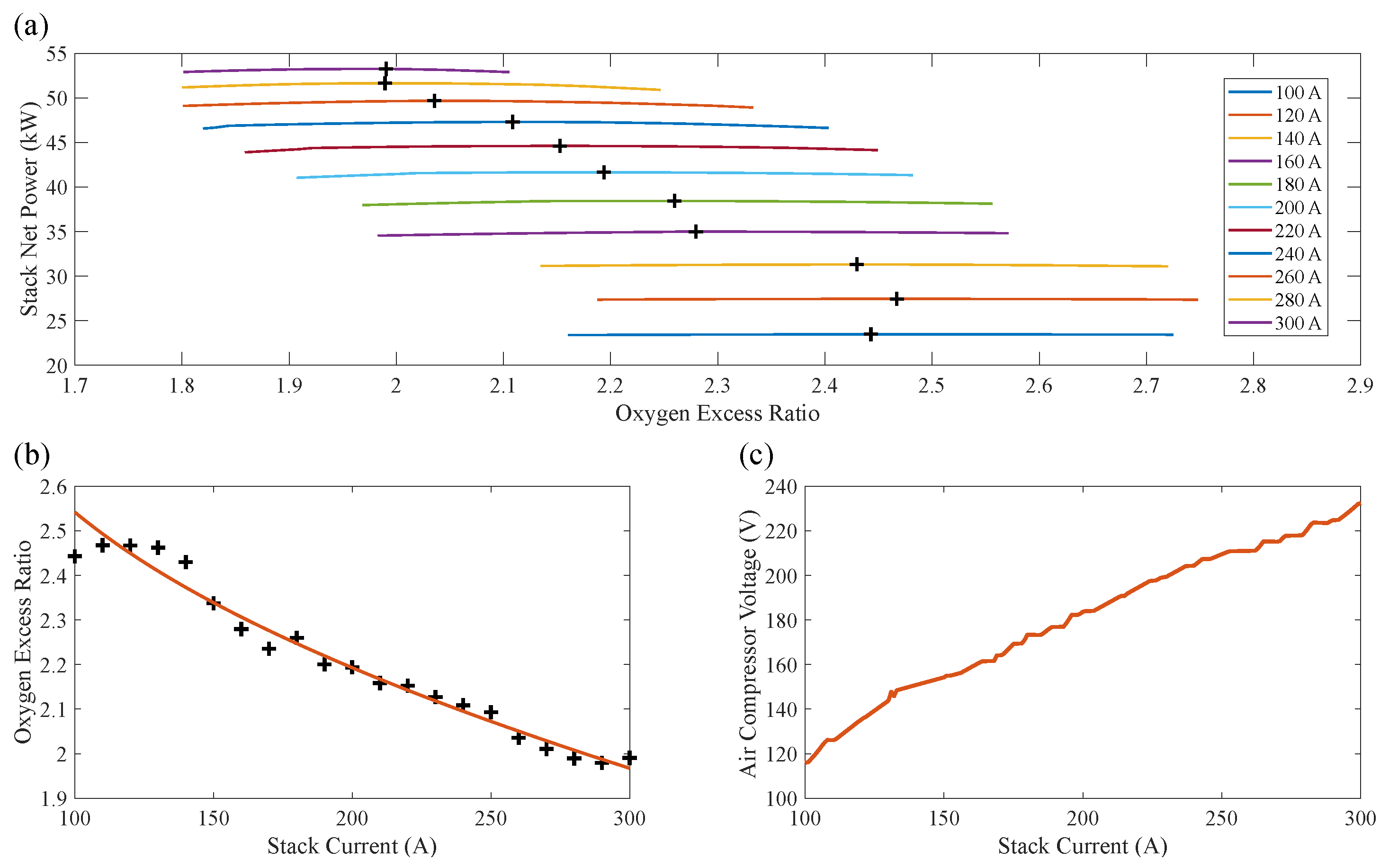
To further demonstrate the control performance of the proposed method, the control results of the two other control methods are discussed and compared. The first is feed-forward open-loop control, whose prior control quantity is determined by the stack current, calculated by
Figure 3c and Equation (
14). The second method is fuzzy PID control, whose parameter settings are as shown in
Figure 6.
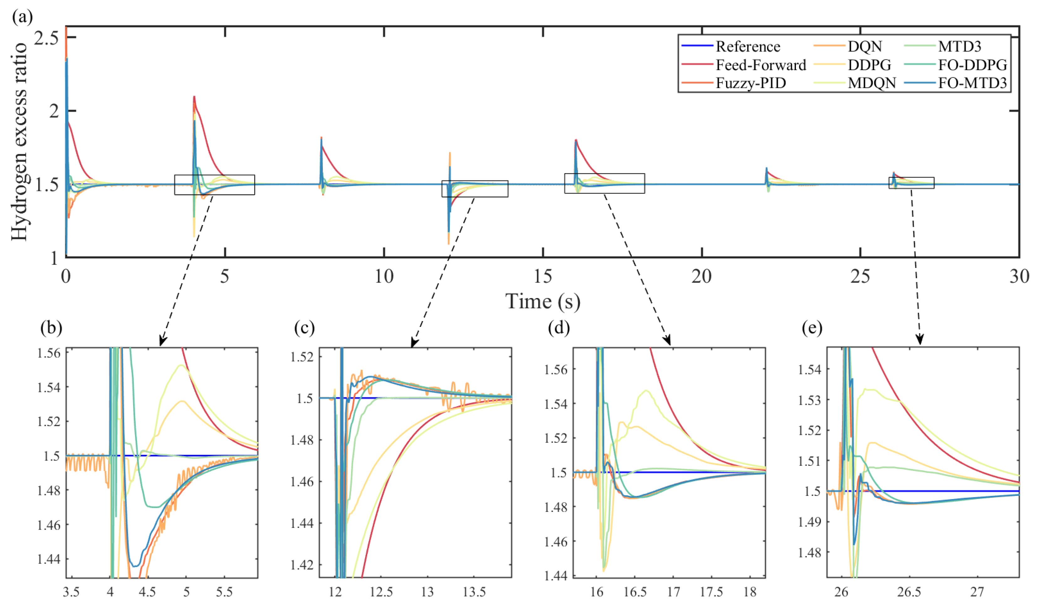
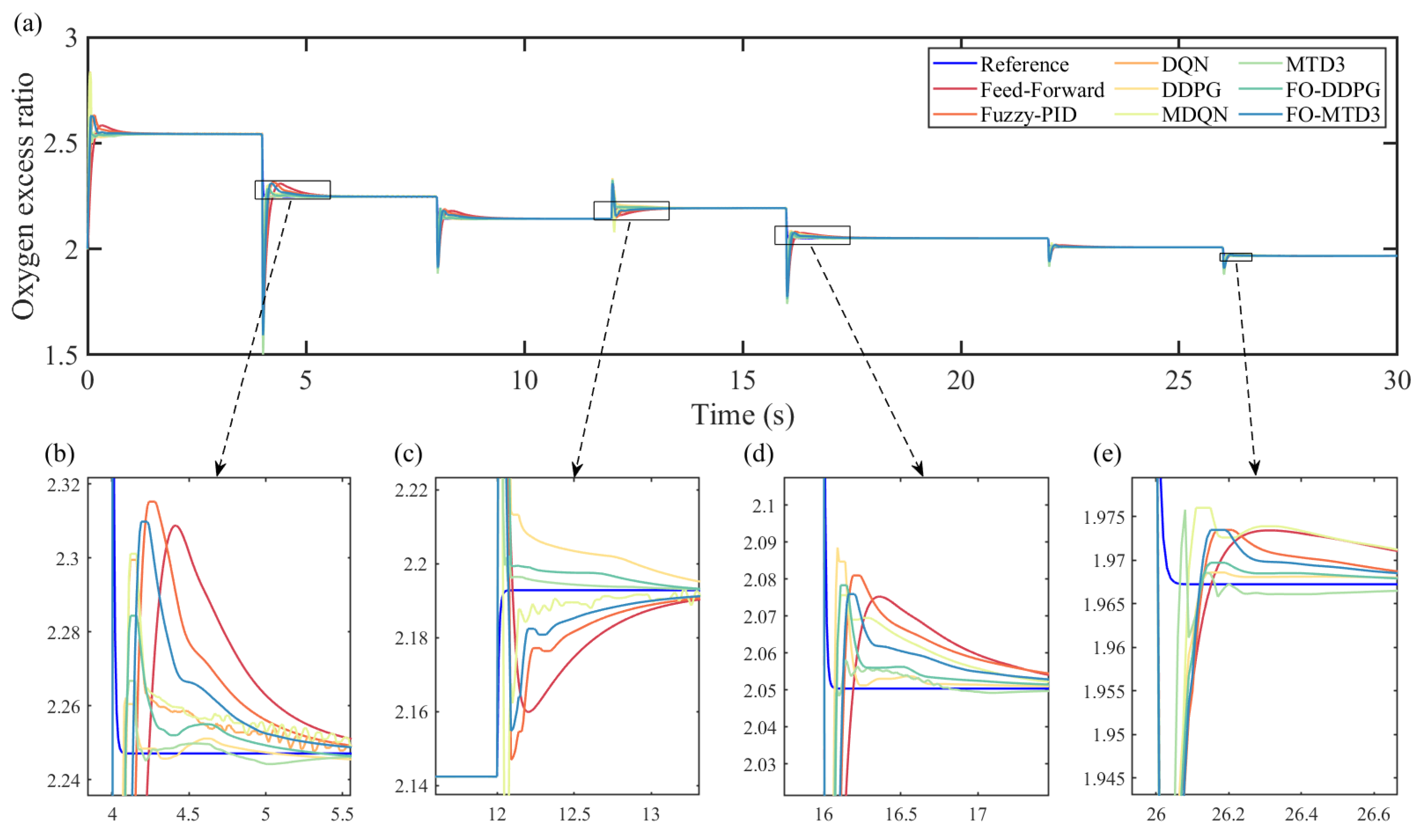
Figure 11 and
Figure 12 show the control results and expected control values for the control quantities and in each of the six methods.
In addition, four parameters are used to measure the control effect of the controllers: the rise time
(error less than 5%), the maximum overshoot
, the root mean square error within 2 s
after the abrupt change of operating conditions, and the root mean square error
when the system reaches stability, which are defined in Equations (
19) and (
20). The calculated results are shown in
Table 3, and the value marked in red represents the optimal effect value of a control algorithm in a variety of control algorithms.
where
n is the number of sampling steps of the whole process, and
and
are the actual and expected values of the ith sampling time, respectively.
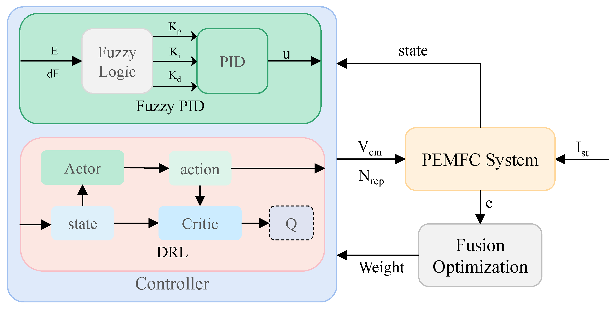
The experimental results show that DQN and MDQN are far inferior to DDPG and MTD3. The MTD3 algorithm has good dynamic characteristics, short rise time, and small overshoot for oxygen supply control, while the coupled DDPG algorithm has good dynamic control for hydrogen supply; when considering the hysteresis of the air compressor, in the control of two-stage differential pressure, it is the anode that follows the cathode, i.e., the hydrogen inflow. HER controlled by the regulating valve on the hydrogen circuit will be affected by the state of the system on the air circuit. In the decoupled control of gas on both sides, the state of the other side is generally not considered, so HER works better in the coupled control. The air circuit belongs to the autonomous control, which is less influenced by the cathode, that is, the state of hydrogen circuit is an irrelevant variable for OER control, so OER is better controlled in the decoupling control, but still not too much better than the coupling control. Although the common DRL algorithm can effectively improve the dynamic response speed of the system, its steady-state performance is far inferior to the common feedforward and fuzzy PID control. FO-DDPG integrates the advantages of DDPG and PID algorithms, improves the dynamic response speed and steady-state performance of the system, and makes the system have better robustness and stability. In a comprehensive comparison, the FO-DDPG algorithm has an overall better control performance.
6. Conclusions
In this paper, a DRL controller with continuous state based on fusion optimization was proposed for a PEMFC gas supply system. By controlling the in and out of air and hydrogen, the combined control of two gas flows in the fuel cell gas supply system was realized. A control strategy based on net power optimization and high economy was also introduced in the experiments, and the need for decoupled control of the two gases was also investigated. These control algorithms were compared with feedforward controllers, fuzzy PID and discrete DRL control algorithms DQN, and conventional continuous DRL algorithms DDPG.
The experimental results show that the FO-DDPG algorithm proposed in this paper has a faster dynamic response and stable static performance compared to the traditional fuzzy PID, DQN, and DDPG algorithms. Specifically, for the two controlled quantities, the dynamic response time is only 0.1 5 s, the overshoot is less than 5%, and the stability error of the control quantity is only about 0.00003. That is, the controller can meet the real-time control requirements of the gas supply system under different load conditions, effectively avoiding the undersupply or oversupply of oxygen and hydrogen, and improving the power and economic efficiency of the system.
PEMFC is a highly complex system involving many components, and many areas need to be controlled. The research in this paper is limited to ensuring sufficient supply of the reaction gas and is somewhat ideal for environmental settings. In a real fuel cell system, factors such as temperature and humidity inside the stack can affect the electrochemical reaction and the output voltage of the fuel cell, and the bipolar pressure can also affect the transport of the PEM. In future research, other meta-components can be introduced to further improve the efficiency of the fuel cell by constructing a multi-physical quantity multi-dimensional fuel cell model and designing a gas-water-heat-electric coordinated integrated controller to realize the joint control of power, pressure, temperature, and humidity of the fuel cell.


