
Improved Model Predictive Current Control of NPC Three-Level Converter Fed PMSM System for Neutral Point Potential Imbalance Suppression


Abstract
:1. Introduction
2. Conventional MPCC
- (1)
- Stator currents and neutral point potentials are sampled at kTs;
- (2)
- From (3) and (4), , and at (k + 1)Ts are obtained and can be used as the initial values of the algorithm;
- (3)
- The sector in which the optimal vector of the last control period was located is determined, and the alternative vector set can be established as Table 2. The alternative vectors in Table 2 are substituted into (3) and (4) to obtain (n), (n) and (n) at (k + 2)Ts, n = 1, 2,…, m, where m denotes the number of alternative vectors;
- (4)
- According to (5), the cost function corresponding to each alternative voltage vector in the FCS is calculated, and the voltage vector corresponding to the minimum value of the cost function is selected to act on the converter.
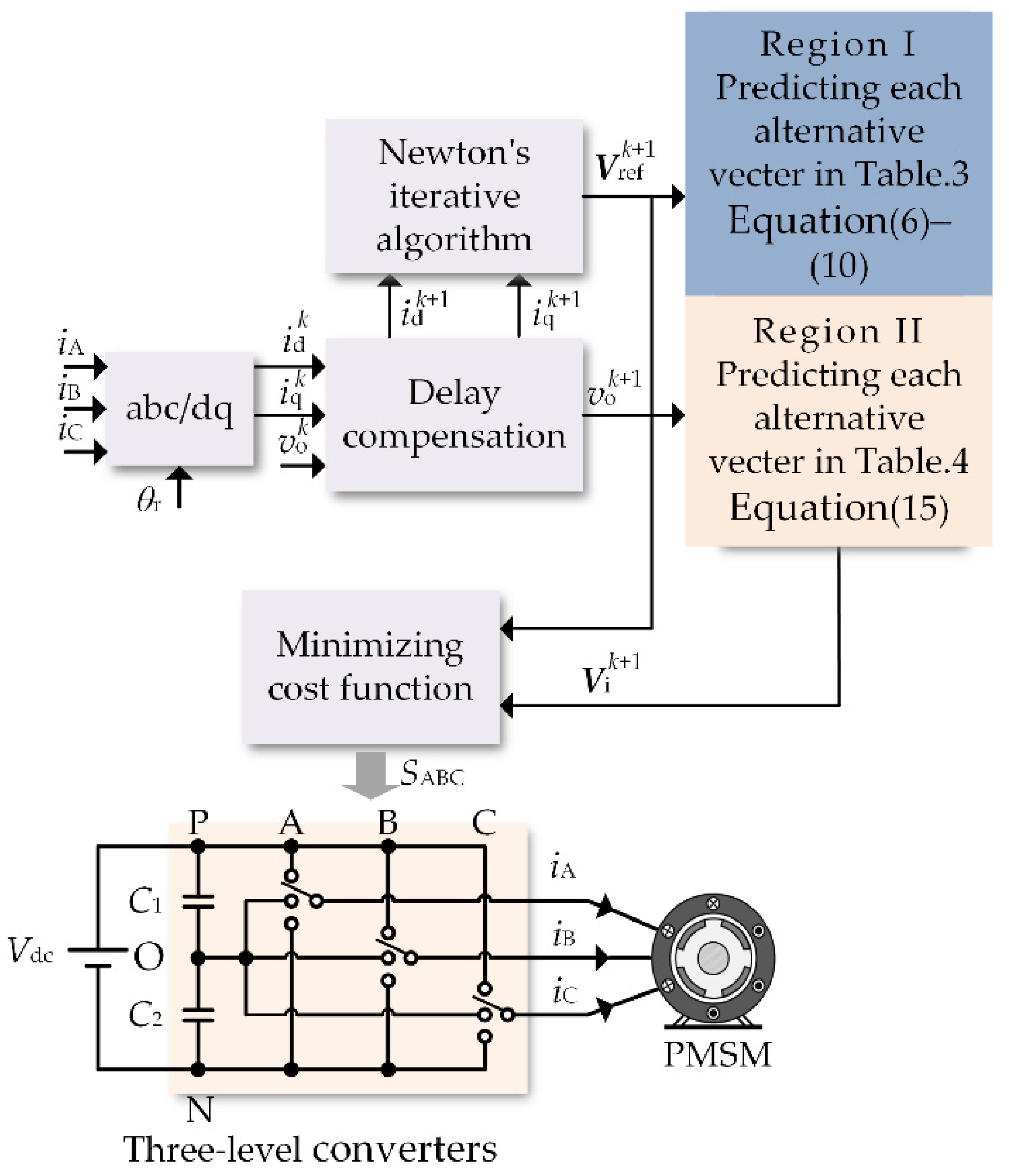
3. Proposed MPCC
3.1. Newton’s Iterative Algorithm
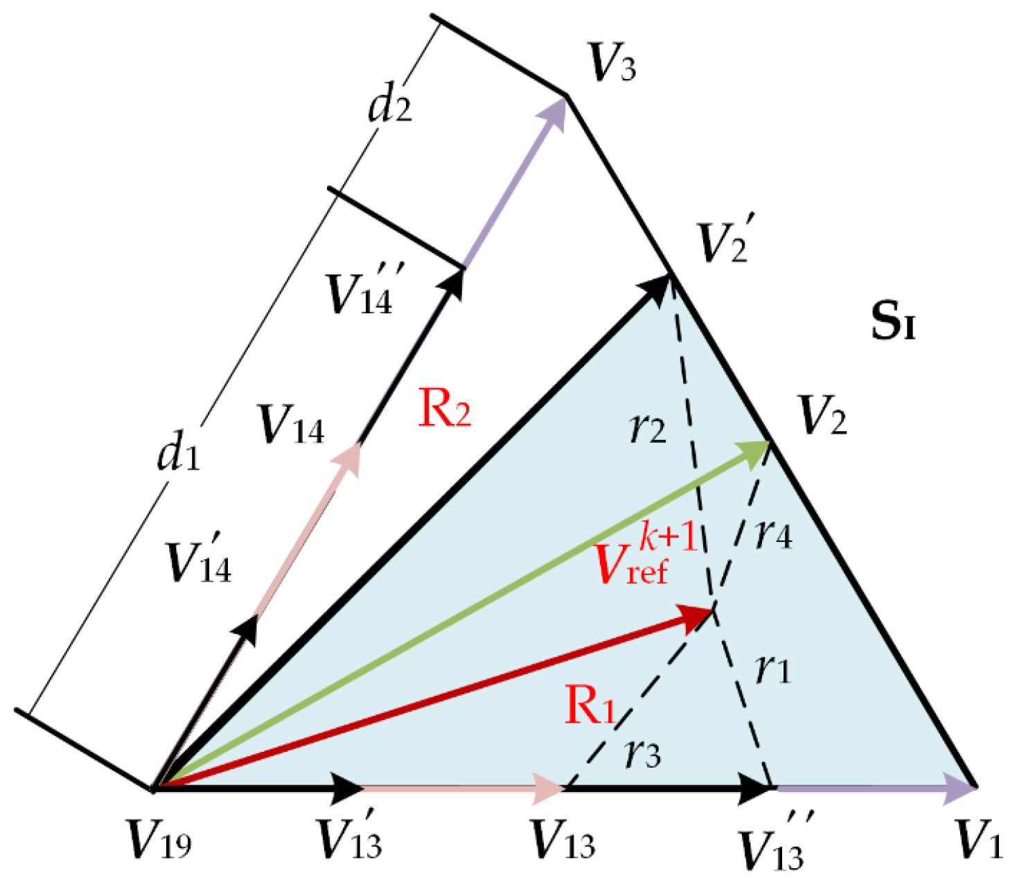
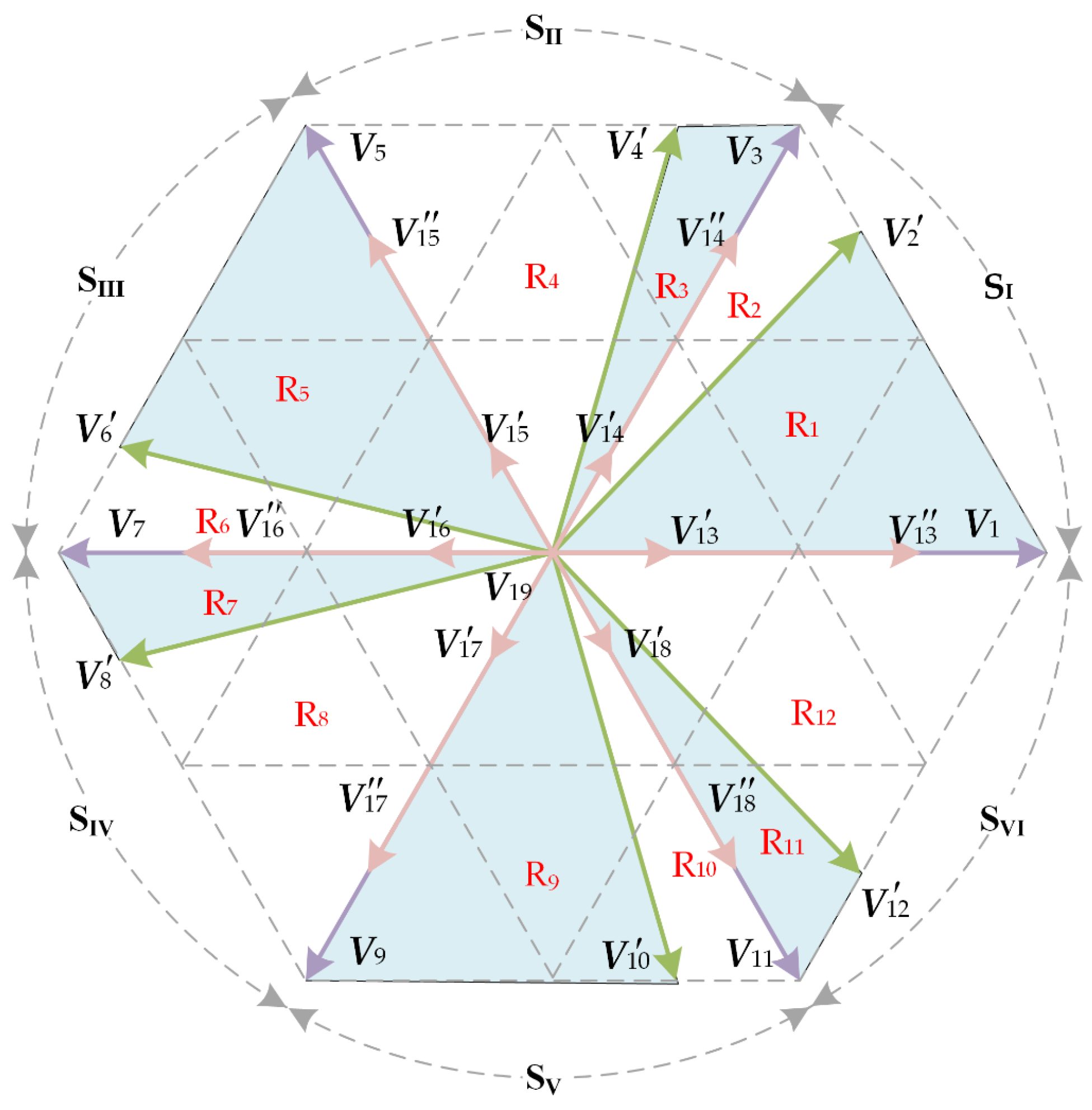
3.2. Dynamic Division of Sectors
3.3. The Partition Control of Neutral Point Potential Imbalance
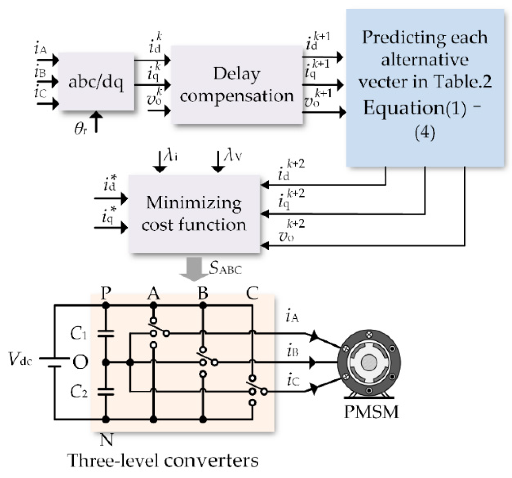
- (1)
- The stator current and the neutral point potential are sampled at kTs;
- (2)
- From (3) and (4), , and at (k + 1)Ts are obtained and can be used as the initial values of the algorithm;
- (3)
- The reference voltage vector is calculated by (6) and the FCS is selected according to the amplitude of the neutral point potential;
- (4)
- The alternative vector with the minimum value of the cost function is selected as the optimal vector and applied to the converter.
4. Experimental Results
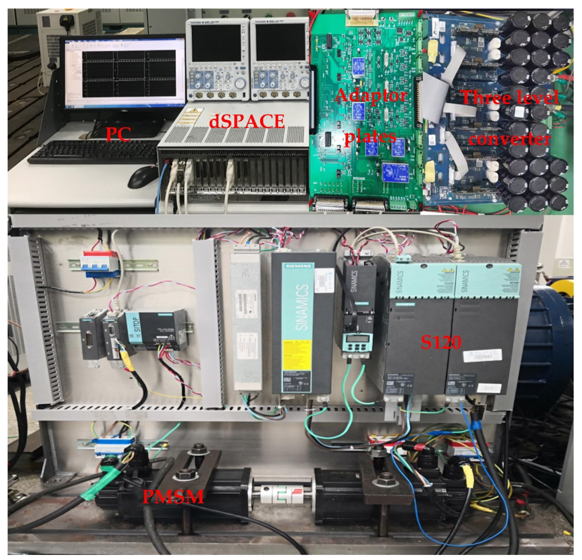
4.1. Experimental Platform
4.2. Experimental Analysis
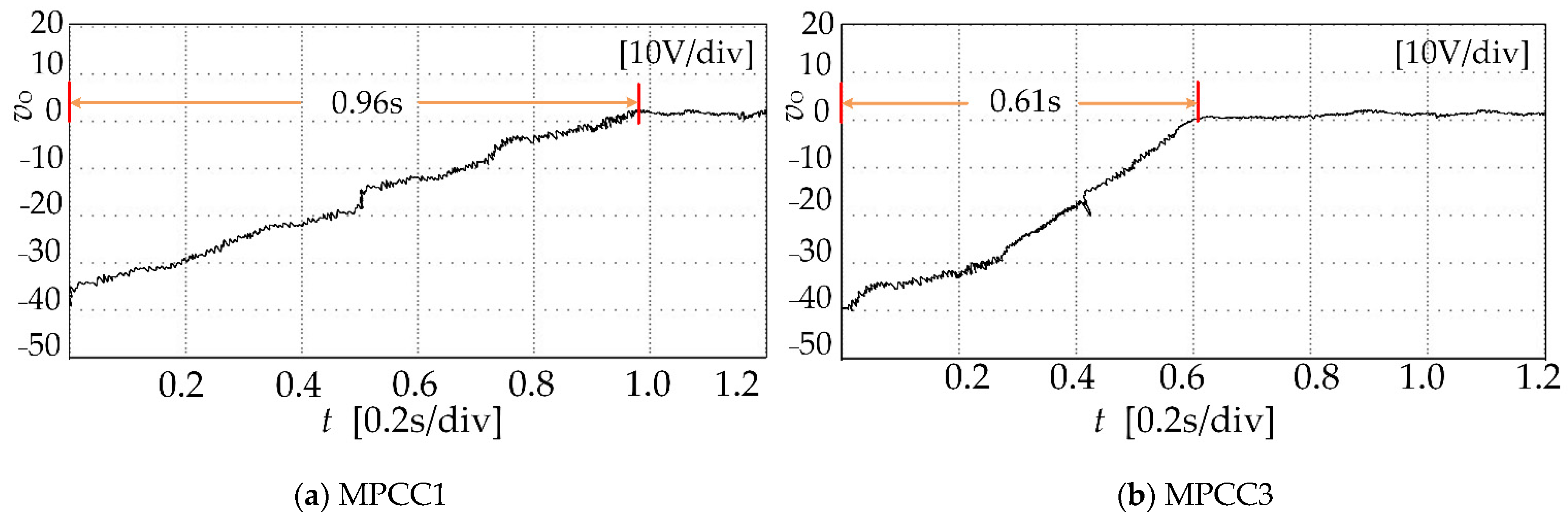
4.2.1. Control Performance of the Neutral Point Potential
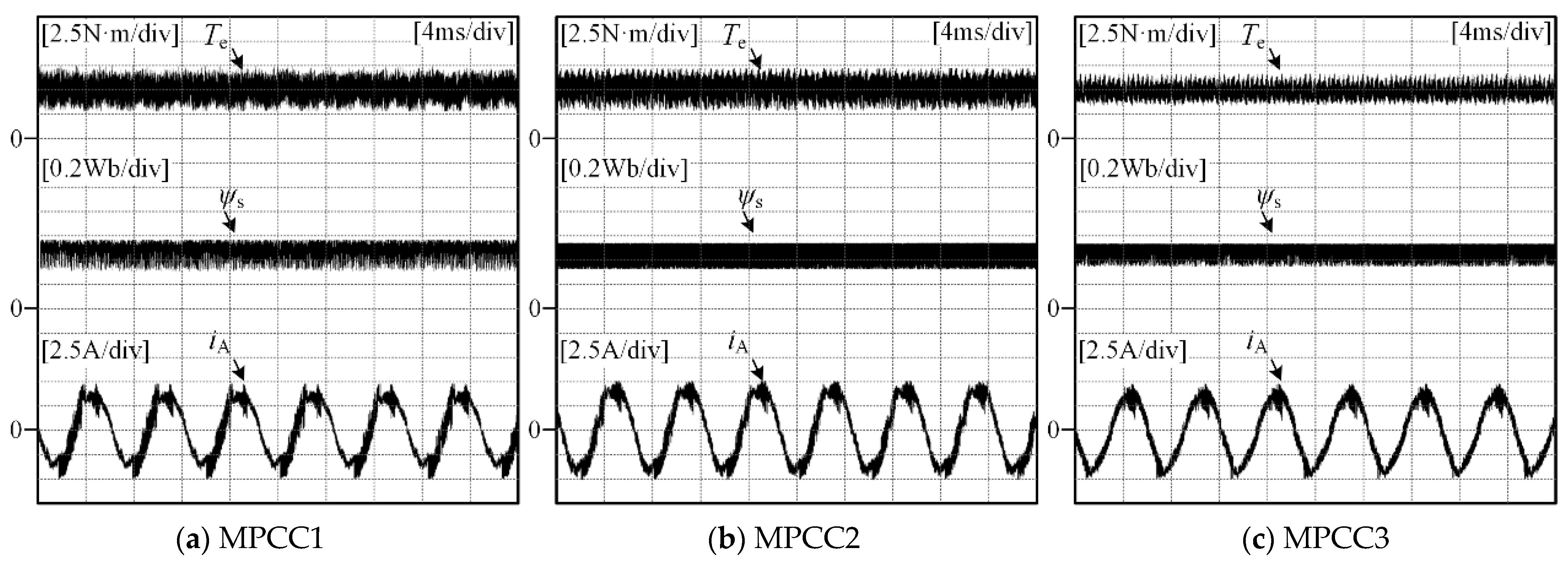
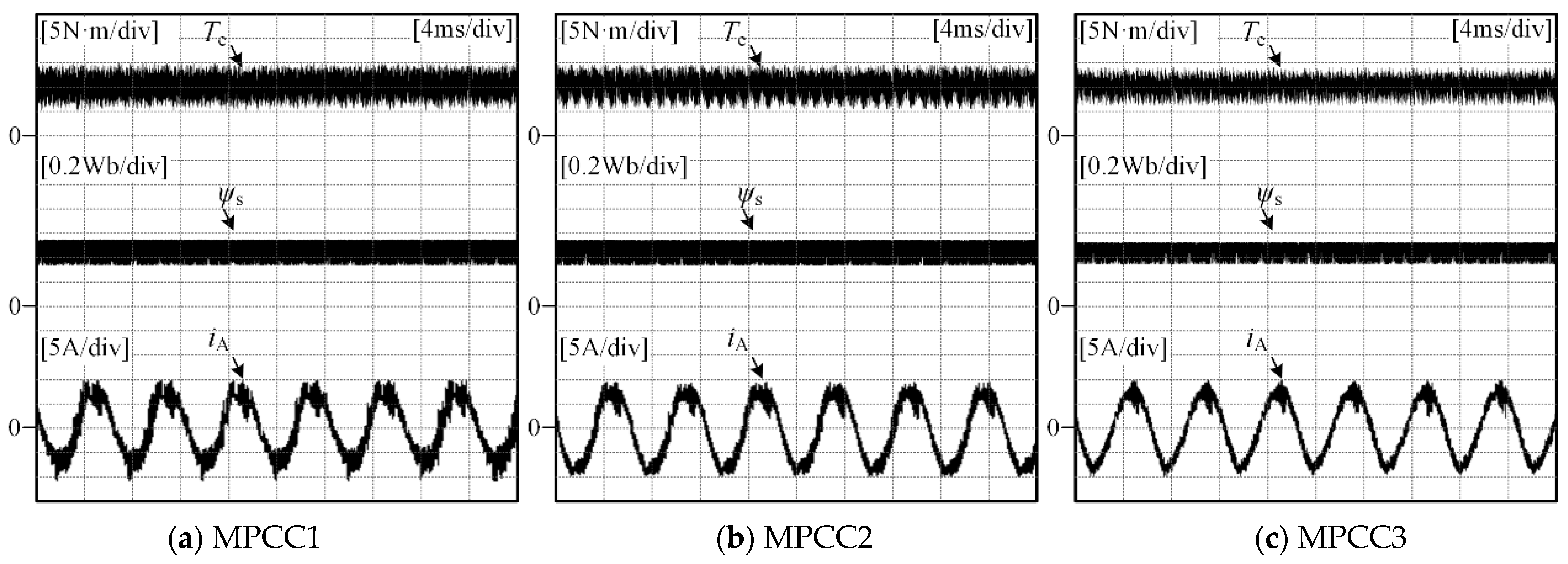
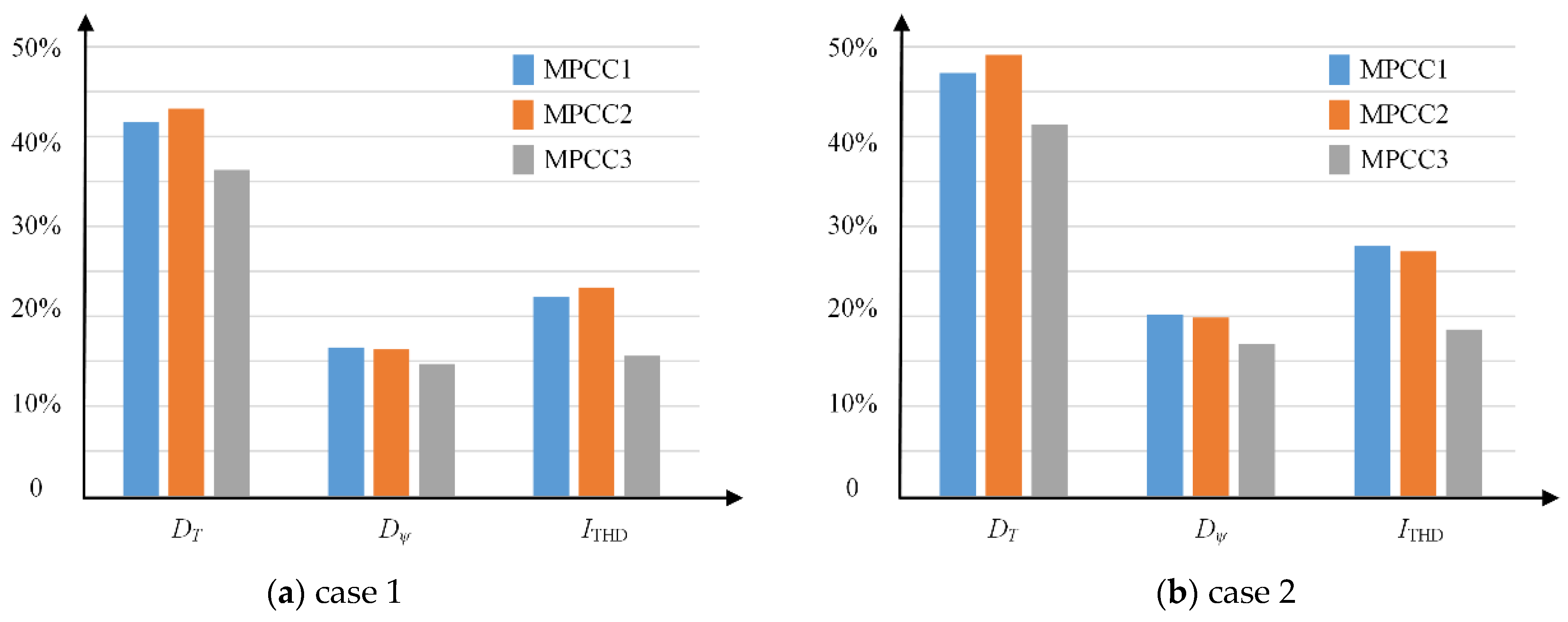
4.2.2. Control Performance under Steady State
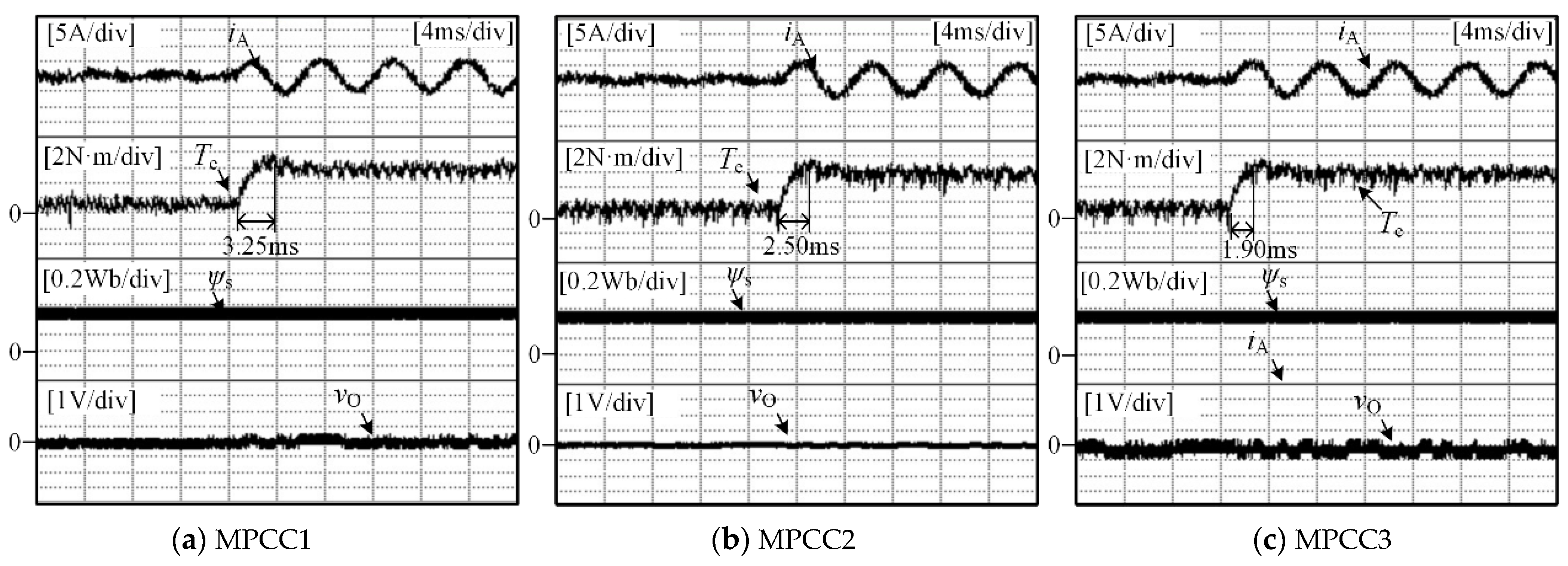
4.2.3. Control Performance under Dynamic State
5. Conclusions
Author Contributions
Funding
Institutional Review Board Statement
Informed Consent Statement
Conflicts of Interest
References
- Cho, Y.; Lee, K.B.; Song, J.H.; Lee, Y., II. Torque-ripple minimization and fast dynamic scheme for torque predictive control of per-manent-magnet synchronous motors. IEEE Trans. Power Electron. 2015, 4, 2182–2190. [Google Scholar] [CrossRef]
- Rodriguez, J.; Bernet, S.; Steimer, P.K.; Lizama, I.E. A survey on neutral-point-clamped inverters. IEEE Trans. Ind. Electron. 2010, 57, 2219–2230. [Google Scholar] [CrossRef]
- Yang, Y.; Wen, H.; Fan, M.; Xie, M.; Chen, R. A fast finite-switching-state model predictive control method without weighting factors for T-type three-level three-phase inverters. IEEE Trans. Power Electron. 2019, 15, 1298–1310. [Google Scholar] [CrossRef]
- Xia, C.; Zhang, G.; Yan, Y.; Gu, X.; Shi, T.; He, X. Discontinuous space vector PWM strategy of neutral-point-clamped three-level inverters for output current ripple reduction. IEEE Trans. Power Electron. 2017, 32, 5109–5121. [Google Scholar] [CrossRef]
- Schweizer, M.; Friedli, T.; Kolar, J.W. Comparative evaluation of advanced three-phase three-level inverter/converter to-pologies against two-level systems. IEEE Trans. Ind. Electron. 2013, 12, 5515–5527. [Google Scholar] [CrossRef]
- Zhang, X.; Hou, B. Double vectors model predictive torque control without weighting factor based on voltage tracking error. IEEE Trans. Power Electron. 2018, 33, 2368–2380. [Google Scholar] [CrossRef]
- Wang, Y.; Wang, X.; Xie, W.; Wang, F.; Dou, M.; Kennel, R.M.; Lorenz, R.D.; Gerling, D. Deadbeat Model-Predictive Torque Control With Discrete Space-Vector Modulation for PMSM Drives. IEEE Trans. Ind. Electron. 2017, 64, 3537–3547. [Google Scholar] [CrossRef]
- Xia, C.; Qiu, X.; Wang, Z.; Shi, T. Predictive torque control based on optimal operating time of vector. Proc. CSEE 2016, 36, 3045–3053. [Google Scholar]
- Xu, Y.; Li, Y.; Zhang, B.; Qin, Z. Three-vector based model predictive torque control of eliminating weighting factor. Trans. China Electrotech. Soc. 2018, 33, 3925–3934. [Google Scholar]
- Zhang, Y.; Yang, H. Generalized two-vector-based model predictive torque control of induction motor drives. IEEE Trans. Power Electron. 2015, 30, 3818–3829. [Google Scholar] [CrossRef]
- Zhang, Y.; Yang, H. Model-predictive flux control of induction motor drives with switching instant optimization. IEEE Trans. Energy Convers. 2015, 30, 1113–1122. [Google Scholar] [CrossRef]
- Xia, C.; Zhang, T.; Zhou, Z.; Zhang, G. Model predictive torque control with switching table for neutral point clamped three-level inverter-fed PMSM. Trans. China 12 Electrotech. Soc. 2016, 31, 83–92. [Google Scholar]
- Xie, W.; Wang, X.; Wang, F.; Xu, W.; Kennel, R.M.; Gerling, D.; Lorenz, R.D. Finite-Control-Set Model Predictive Torque Control with a Deadbeat Solution for PMSM Drives. IEEE Trans. Ind. Electron. 2015, 62, 5402–5410. [Google Scholar] [CrossRef]
- Rojas, C.A.; Rodriguez, J.; Villarroel, F.; Espinoza, J.R.; Silva, C.A.; Trincado, M. Predictive torque and flux control without weighting factors. IEEE Trans. Ind. Electron. 2013, 60, 681–690. [Google Scholar] [CrossRef]
- Yang, Y.; Chen, R.; Fan, M.; Xiao, Y.; Zhang, X.; Norambuena, M.; Rodriguez, J. Improved Model Predictive Current Control for Three-Phase Three-Level Converters with Neutral-Point Voltage Ripple and Common Mode Voltage Reduction. IEEE Trans. Energy Convers. 2021, 36, 3053–3062. [Google Scholar] [CrossRef]
- Alhosaini, W.; Diao, F.; Mahmud, M.H.; Wu, Y.; Zhao, Y. A Virtual Space Vector-Based Model Predictive Control for Inherent DC-Link Voltage Balancing of Three-Level T-Type Converters. IEEE J. Emerg. Sel. Top. Power Electron. 2020, 9, 1751–1764. [Google Scholar] [CrossRef]
- Jun, E.-S.; Nguyen, M.H.; Kwak, S.-S. Model Predictive Control Method With NP Voltage Balance by Offset Voltage Injection for Three-Phase Three-Level NPC Inverter. IEEE Access 2020, 8, 172175–172195. [Google Scholar] [CrossRef]
- Pou, J.; Brnovich, D.; Pintado, R. New feedforward space -vector PWM method to obtain balanced AC output voltages in a three-level neutral-point-clamped converter. IEEE Trans. Power Electron. 2002, 49, 1026–1034. [Google Scholar] [CrossRef]
- Lewicki, A.; Krzeminski, Z.; Abu-Rub, H. Space-vector pulse width modulation for three-level NPC converter with the neutral point voltage control. IEEE Trans. Ind. Electron. 2011, 58, 5076–5086. [Google Scholar] [CrossRef]
- Xiang, C.-Q.; Shu, C.; Han, D.; Mao, B.-K.; Wu, X.; Yu, T.-J. Improved Virtual Space Vector Modulation for Three-Level Neutral-Point-Clamped Converter With Feedback of Neutral-Point Voltage. IEEE Trans. Power Electron. 2017, 33, 5452–5464. [Google Scholar] [CrossRef]
- Lopez, I.; Ceballos, S.; Pou, J.; Zaragoza, J.; Andreu, J.; Kortabarria, I.; Agelidis, V.G. Modulation Strategy for Multiphase Neutral-Point-Clamped Converters. IEEE Trans. Power Electron. 2015, 31, 928–941. [Google Scholar] [CrossRef]
- Kakosimos, P.; Abu-Rub, H. Predictive Speed Control with Short Prediction Horizon for Permanent Magnet Synchronous Motor Drives. IEEE Trans. Power Electron. 2017, 33, 2740–2750. [Google Scholar] [CrossRef]


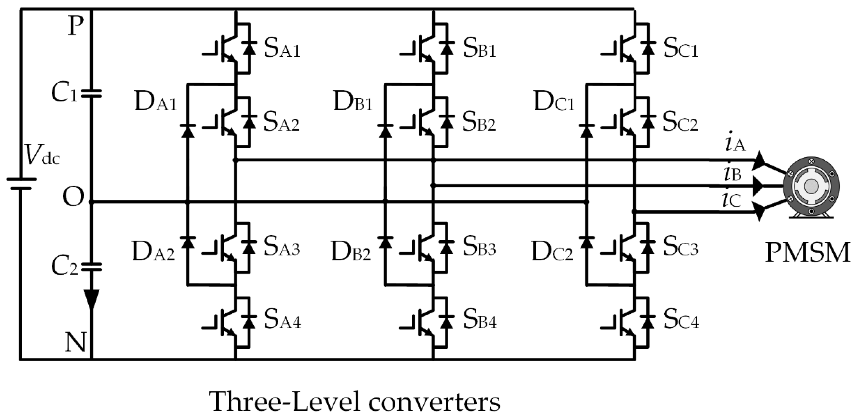
| State | Sx1 | Sx2 | Sx3 | Sx4 | Output Voltage |
|---|---|---|---|---|---|
| P | 1 | 1 | 0 | 0 | Vdc/2 |
| O | 0 | 1 | 1 | 0 | 0 |
| N | 0 | 0 | 1 | 1 | −Vdc/2 |
| Vectors Used in the Last Control Period | Alternative Voltage Vectors | ||||||
|---|---|---|---|---|---|---|---|
| V1 | V1 | V2 | V12 | V13 | V19 | ||
| V2 | V1 | V2 | V3 | V13 | V14 | V19 | |
| V3 | V2 | V3 | V4 | V14 | V19 | ||
| V4 | V3 | V4 | V5 | V14 | V15 | V19 | |
| V5 | V4 | V5 | V6 | V15 | V19 | ||
| V6 | V5 | V6 | V7 | V15 | V16 | V19 | |
| V7 | V6 | V7 | V8 | V16 | V19 | ||
| V8 | V7 | V8 | V9 | V16 | V17 | V19 | |
| V9 | V8 | V9 | V10 | V17 | V19 | ||
| V10 | V9 | V10 | V11 | V17 | V18 | V19 | |
| V11 | V10 | V11 | V12 | V18 | V19 | ||
| V12 | V1 | V11 | V12 | V13 | V18 | V19 | |
| V13 | V1 | V2 | V12 | V13 | V19 | ||
| V14 | V2 | V3 | V4 | V14 | V19 | ||
| V15 | V4 | V5 | V6 | V15 | V19 | ||
| V16 | V6 | V7 | V8 | V16 | V19 | ||
| V17 | V8 | V9 | V10 | V17 | V19 | ||
| V18 | V10 | V11 | V12 | V18 | V19 | ||
| V19 | V13 | V14 | V15 | V16 | V17 | V18 | V19 |
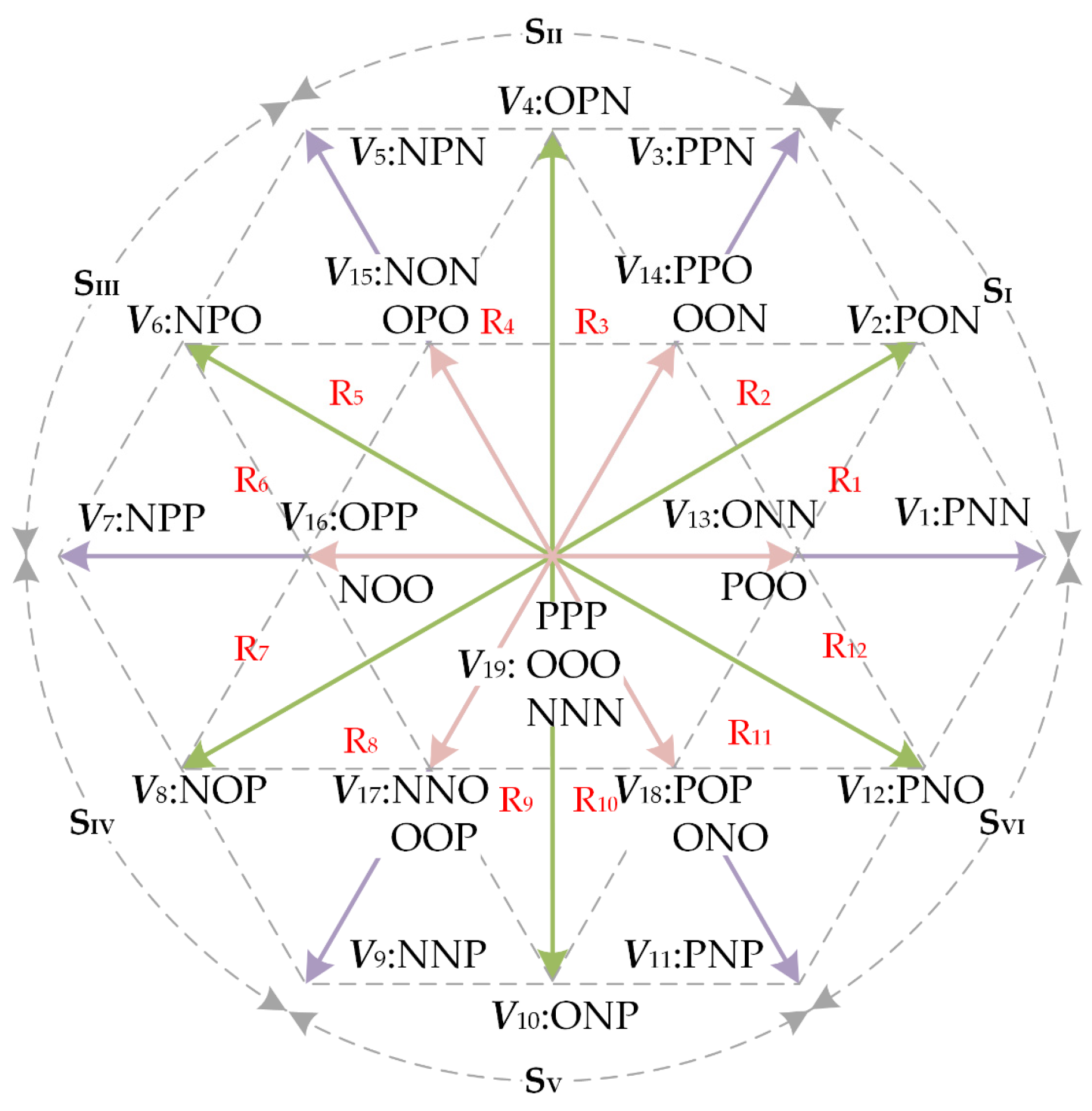
| Sectors | Alternative Voltage Vectors | |||
|---|---|---|---|---|
| R1 | V1 | V2 | V13 | V19 |
| R2 | V2 | V3 | V14 | V19 |
| R3 | V3 | V4 | V14 | V19 |
| R4 | V4 | V5 | V15 | V19 |
| R5 | V5 | V6 | V15 | V19 |
| R6 | V6 | V7 | V16 | V19 |
| R7 | V7 | V8 | V16 | V19 |
| R8 | V8 | V9 | V17 | V19 |
| R9 | V9 | V10 | V17 | V19 |
| R10 | V10 | V11 | V18 | V19 |
| R11 | V11 | V12 | V18 | V19 |
| R12 | V12 | V1 | V13 | V19 |
| Sectors | Alternative Voltage Vectors | ||
|---|---|---|---|
| R1 | |||
| R2 | |||
| R3 | |||
| R4 | |||
| R5 | |||
| R6 | |||
| R7 | |||
| R8 | |||
| R9 | |||
| R10 | |||
| R11 | |||
| R12 | |||
| Parameters | Symbol | Value | Unit |
|---|---|---|---|
| Poles | p | 4 | - |
| Permanent magnet flux | ψf | 0.45 | Wb |
| Stator resistance | Rs | 0.635 | Ω |
| d-axis inductance | Ld | 4.25 | mH |
| q-axis inductance | Lq | 4.25 | mH |
| Rated speed | nr | 1500 | r/min |
| Rated torque | TN | 10 | N·m |
| Rated voltage | VN | 220 | V |
Publisher’s Note: MDPI stays neutral with regard to jurisdictional claims in published maps and institutional affiliations. |
© 2022 by the authors. Licensee MDPI, Basel, Switzerland. This article is an open access article distributed under the terms and conditions of the Creative Commons Attribution (CC BY) license (https://creativecommons.org/licenses/by/4.0/).
Share and Cite
Zhang, G.; Liu, Q.; Wang, J.; Li, C.; Gu, X. Improved Model Predictive Current Control of NPC Three-Level Converter Fed PMSM System for Neutral Point Potential Imbalance Suppression. World Electr. Veh. J. 2022, 13, 113. https://doi.org/10.3390/wevj13070113
Zhang G, Liu Q, Wang J, Li C, Gu X. Improved Model Predictive Current Control of NPC Three-Level Converter Fed PMSM System for Neutral Point Potential Imbalance Suppression. World Electric Vehicle Journal. 2022; 13(7):113. https://doi.org/10.3390/wevj13070113
Chicago/Turabian StyleZhang, Guozheng, Qiyuan Liu, Jian Wang, Chen Li, and Xin Gu. 2022. "Improved Model Predictive Current Control of NPC Three-Level Converter Fed PMSM System for Neutral Point Potential Imbalance Suppression" World Electric Vehicle Journal 13, no. 7: 113. https://doi.org/10.3390/wevj13070113