1. Introduction
With the improvement of people’s living standards, people hope to be provided with wireless power transfer for portable electrical equipment within a certain space [
1,
2,
3,
4,
5]. Wireless power transfer technology has become a key means to solve such problems. The magnetic field-coupled wireless power transfer technology was first commercialized in low-power electronic charging applications [
6]. Although this method is good, it is difficult to provide wireless power to multiple loads simultaneously in a wide space [
7,
8,
9,
10]. Another common method is to use capacitive coupling between conductor plates to transmit electrical energy [
11,
12]. This method of wireless power transfer requires the use of multiple metal plates, and the transfer position is fixed, which is not suitable for wireless power supply of portable electrical equipment. To solve the problem of simultaneous wireless power supply for multiple loads in a wide range, reference [
13] proposed a technology based on single-wire no-return power transmission (SWNR). Nikola Tesla first mentioned this method of power transmission at the end of the 19th century [
14]. In reference [
15], SWNR technology is used to construct a unipolar power transfer equipment device for wireless power transfer to different loads on a wide range of aluminum foil surfaces, realizing wireless power supply in a larger space. However, its power receiving device is large and cylindrical in shape, which makes it difficult to provide wireless power supply for portable electrical equipment. The desktop wireless power transmission system (DWPT) proposed in this paper uses coil inductance and high-frequency capacitance to generate electric field resonance, which generates a high-frequency electric field on a conductive plane the size of a desktop. The power receiving device uses planar PCB resonant coils and high-frequency capacitors, which can receive power at any position above the desktop. The advantage of this wireless power supply system is that it is easier to build, the power receiving device is smaller in size, can be moved arbitrarily, and can provide wireless power to handheld electrical equipment.
2. The Desktop Wireless Power Transfer System Presented in This Article
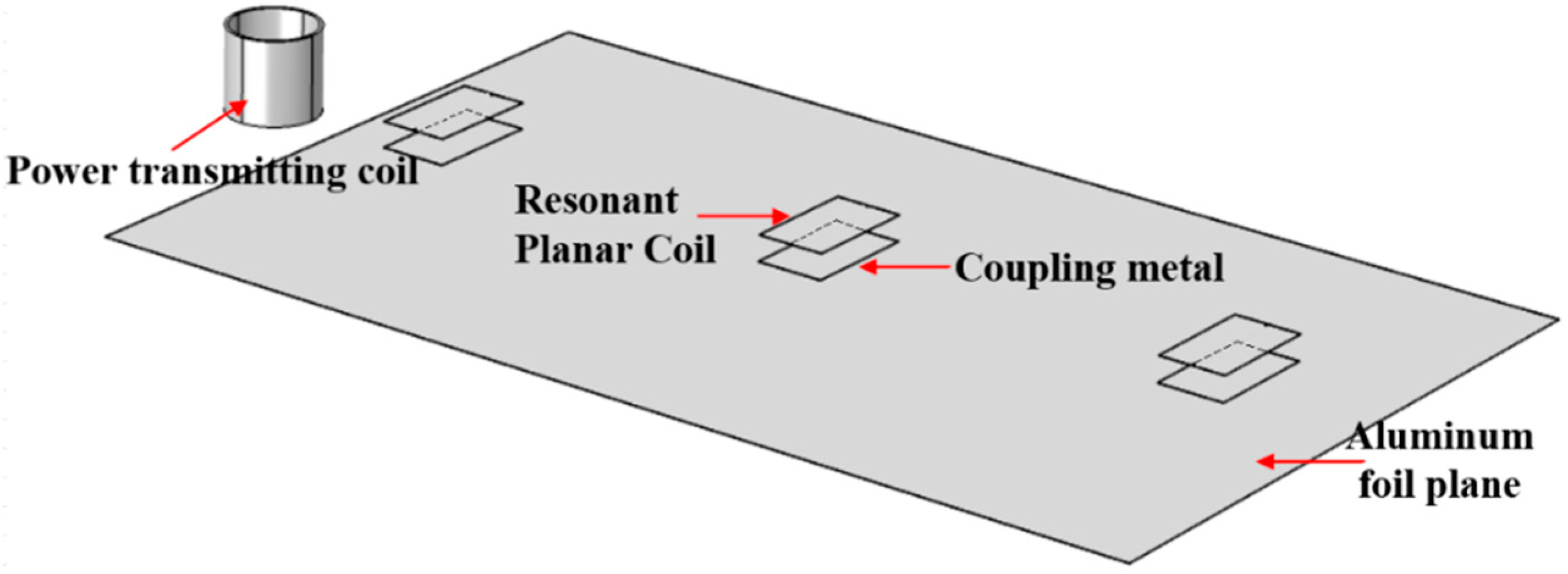
The DWPT system proposed in this article is shown in
Figure 1. The system consists of a high-frequency inverter, an LC resonant circuit on the transmitting side, an aluminum foil plane, and an LC resonant circuit on the receiving side. The lower parallelogram represents the aluminum foil plane, which is connected to the resonance circuit of the power transmitting device on the left. Above the aluminum foil is an electric energy receiving device, and the bottom of the electric energy receiving device is a metal sheet. After rectification and inversion, the grid current provides high-frequency alternating current for the electric energy transmitting device. The inductive and capacitive in the electric energy transmitting device resonate, and then establish a space electric field on the aluminum foil. The metal film at the low end of the electric energy receiving device forms an electric field coupling with the aluminum foil plane to absorb electric energy in the electric field.
To make the power supply performance of the system stable, the LC resonance network is also used as the compensation circuit, and the circuit parameters are basically the same as those of the power transmitting device. The stray capacitance of the aluminum foil plane and the metal film to ground are not consistent, so the transmitting side and the power receiving device are not completely symmetrical in size. The parameters of the LC resonant circuit on the transmitting side and the receiving side of the system are not completely equal. When the system works in resonance, the power transfer effect is the best, the voltage on the aluminum foil plane and the metal film is the highest, and the electric field strength is also the strongest.
3. Circuit Analysis
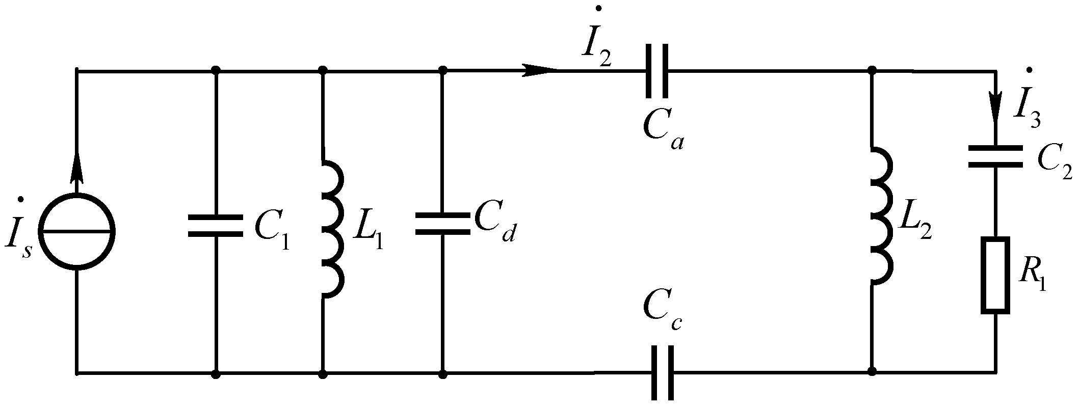
The circuit model of the DWPT system is shown in
Figure 2.
Us is a high frequency alternating voltage source.
L1 and
C1 are transmitting resonant circuits, and their connection nodes are tightly electrically connected to the aluminum foil plane.
Cd is the equivalent capacitance of the aluminum foil plane to the ground.
Ca1,
Ca2, and
Ca3 are the equivalent mutual capacitances between the aluminum foil plane and the metal sheet at the bottom of the power receiving device, respectively.
Cb1,
Cb2, and
Cb3 are the equivalent capacitances between the metal sheets at the bottom of the power receiving device, respectively.
L2,
L3,
L4 and
C2,
C3,
C4 are the receiving resonant circuits for multiple loads, and
Cc1,
Cc2 and
Cc3 represent the stray capacitance to ground.
When the system supplies power to a single load, the circuit model of the DWPT system is shown in
Figure 3.
Figure 4 can be obtained by Norton’s theorem on the power transmitting side. When the quality factor of the inductor and capacitor is high, the line resistance
Rs on the power transmitting side can be ignored.
The output current of the current source in
Figure 4 is:
After simplifying the capacitance, the simplified circuit diagram can be obtained as shown in
Figure 5.
The equivalent capacitance
Cd1 is:
The equivalent impedance
Z1 is:
When the power transmitting side is working in resonance, the resonant angular frequency is:
At this time, it can be considered that the transfer current
I2 is equal to
Is. Ignoring
Ca and spatial stray capacitance
Cc for the time being, the receiving end LC resonance network can be simplified to the circuit diagram shown in
Figure 6.
The Thevenin equivalent transformation of the receiving side resonant circuit can be obtained, as shown in
Figure 7.
When the power receiving device works at the resonance frequency, the resonance angular frequency is:
The current on the load is:
The power received by the load is:
When the system is working in resonance, the resonance frequency
f should satisfy:
To facilitate system design,
C1 =
C2. This is because
Cd1 >
C2,
L1 <
L2. It can be calculated that
L1 is equal to:
4. Electromagnetic Field Simulation
To simulate the actual working environment of the DWPT, a simulation model is established in the FEM software COMSOL Multiphysics as shown in
Figure 8. The parallelogram at the bottom of the simulation diagram is the power supply desktop, the material is aluminum foil, and the area is 1.2 m
2. The cylinder on the left side of the simulation diagram is the resonant coil of the electric energy transmitting device, its height is 12 cm, and the number of turns is 40. Three sets of metal sheets in the middle of the simulation diagram are power receiving devices, where the upper sheet of each set of devices is a resonant planar coil, and the lower sheet is a coupling metal.
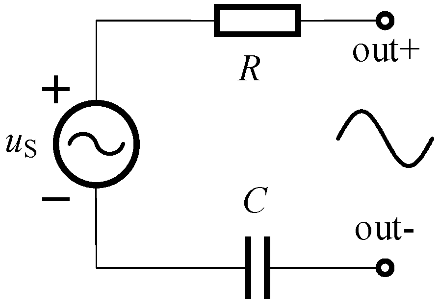
An excitation port is connected between the two electrodes, and a high-frequency power supply is used to provide a high-frequency current to the resonant coil through a series resonant capacitor. The power supply circuit is shown in
Figure 9. The voltage source amplitude is 20 V;
R is the equivalent internal resistance of the power supply;
C is the resonant capacitor.
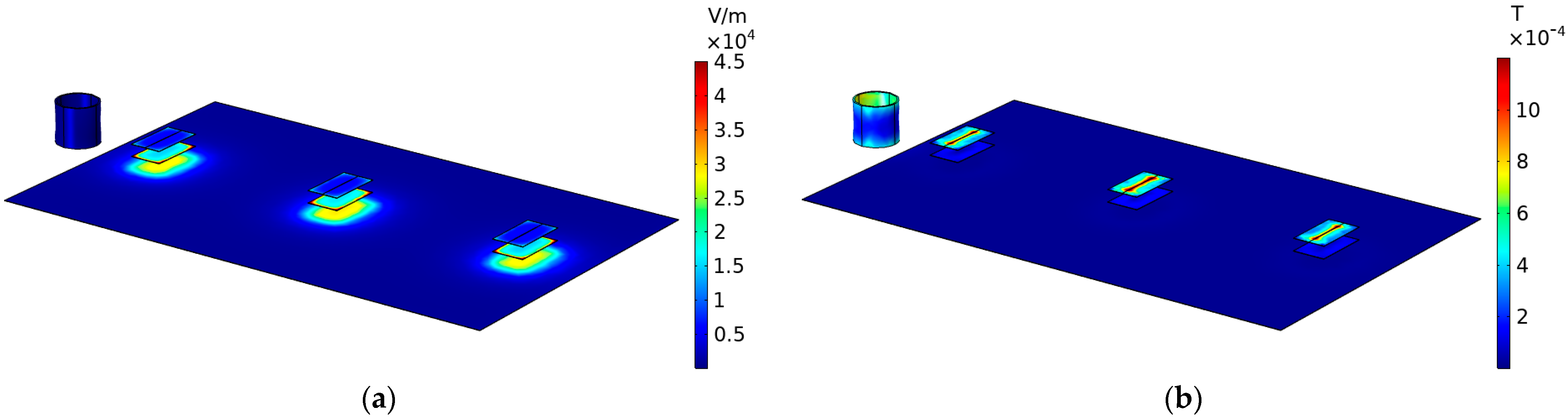
The electromagnetic field simulation diagram by FEM of the DWPT is shown in
Figure 10. In the electric field distribution simulation diagram, the electric field is concentrated at the coupling point of the power receiving device and the power supply desktop, and the electric field radiation in other spaces is weak. The electric field strength of the resonant coil on the left and the resonant plane coil in the middle is weak, and the electric field strength is the strongest at the metal film of the receiving device. The metal film can receive the electric energy from the aluminum foil, and then wirelessly power the load. In the magnetic field distribution simulation diagram, the resonant coil on the power transmitting side on the left and the resonant planar coil on the power receiving side in the middle have a strong internal magnetic field, and the magnetic field distribution in the remaining space is very weak. According to the electromagnetic field distribution law, the power supply system relies on the resonant space electric field to provide energy for the load.
A simulation diagram of electric field distribution in the vertical direction is shown in
Figure 11. The electric field is concentratedly distributed near the coupling aluminum foil under the power receiving device and does not spread outward. When the system supplies power to low-power electrical equipment, the electric field strength in most areas around the desktop is relatively weak, and electromagnetic interference to electronic equipment near the desktop is relatively weak.
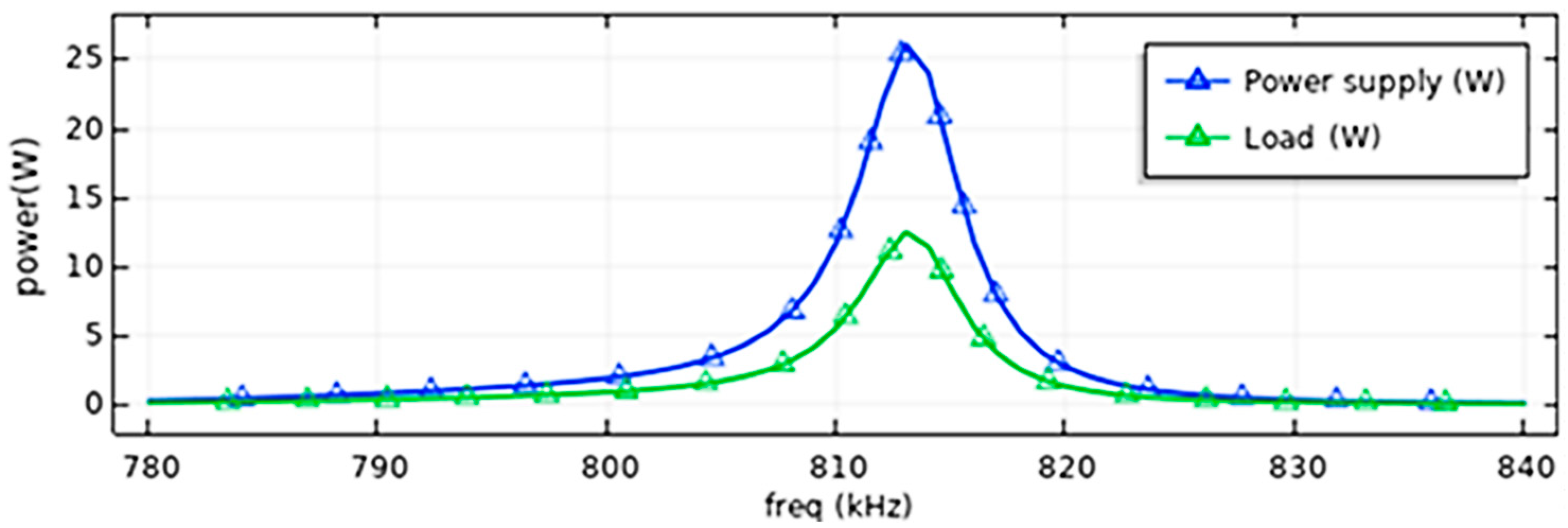
When the load is 30 Ω, the relationship between the operating frequency of the system and the load power can be obtained from the COMSOL simulation software as shown in
Figure 12. When the system works at 813 kHz, the load power value reaches the maximum. At this time, the active power provided by the power supply is 26.1 W, and the load is 12.5 W. After calculation, the transfer efficiency of the system is 46%.
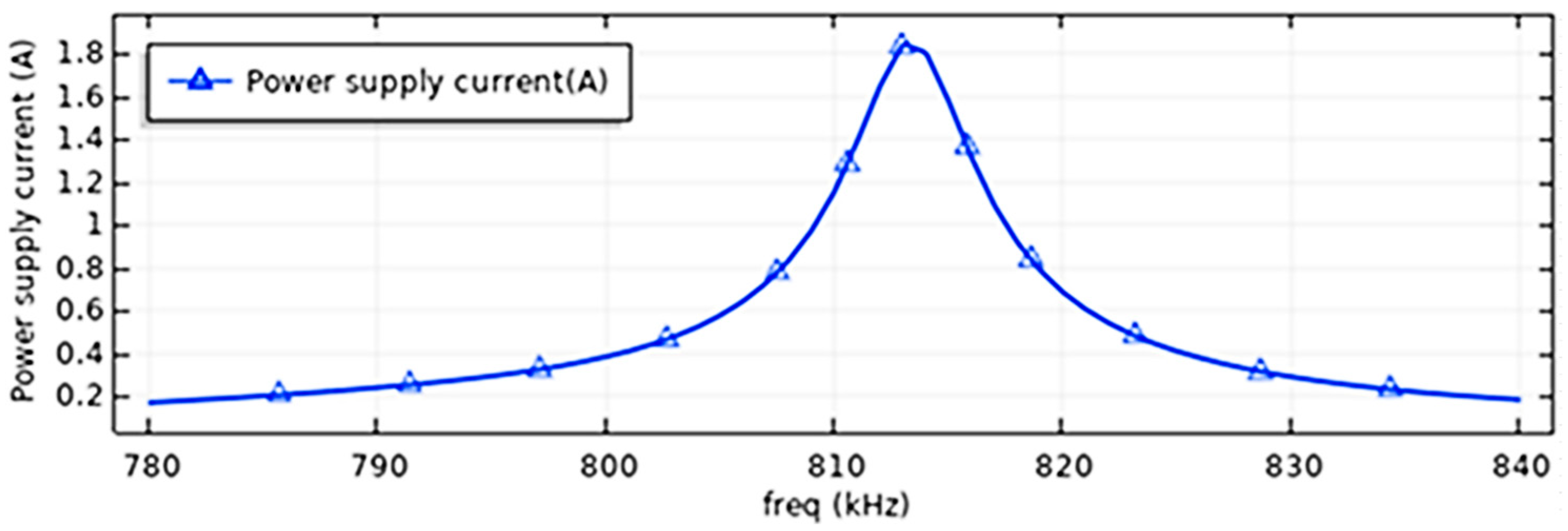
Figure 13 shows the relationship between power supply current and operating frequency. When the effective value of the power supply voltage is 20 V, the system has the maximum power supply current at a frequency of 813 kHz, and the effective value of the current can reach 1.8 A. At the non-resonant operating frequency, the power supply current is only 0.2 A.
To reflect the resonance of the system, the power supply voltage phase is taken as the reference phase, and the cosine value of the angle between the power supply current and the voltage is defined as the system power factor. As shown in
Figure 14, it is the power factor characteristic curve of the desktop wireless power transfer system. When the output frequency of the power supply is 813 kHz, the system resonates, the system power factor is the largest, and the system transfer effect is the best.
5. Experimental Results and Discussion
To verify the feasibility of the DWPT system, a desktop wireless power transfer experimental platform was built. Initially, the combination of Tektronix AFG3022 signal generator and HSA4012 power amplifier was used as the high-frequency power supply to provide high-frequency AC power for the system.
Table 1 shows the parameters of each component of the DWPT system in the experiment.
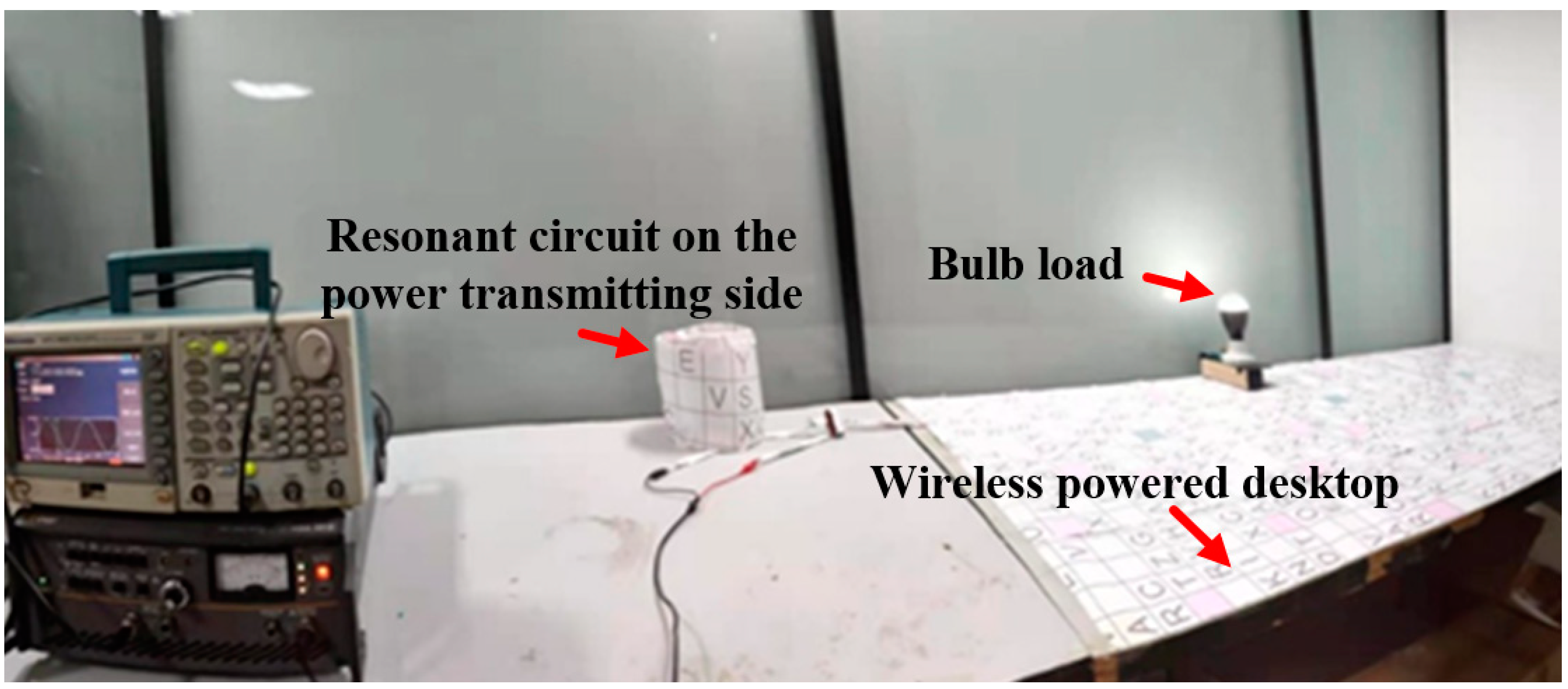
The experimental platform built according to the parameters in the above table is shown in
Figure 15. The left side of the figure is a high-frequency AC power supply composed of a signal generator and a power amplifier. The white cylinder in the middle is a resonant coil on the power transmitting side. The coil has 40 turns and a height of 12 cm. The outer side of the resonant coil is wrapped with insulating paper. Next to the white cylinder is a high-frequency resonant capacitor. The connection between the resonant capacitor and the resonant inductance is closely connected to the power supply desktop to provide high-frequency power for the power supply desktop. The power supply desktop is composed of aluminum foil and insulating paper, with an area of 1.2 m
2. On the right is the power receiving device. The power receiving device consists of a planar resonance coil, a high-frequency resonance capacitor, a high-frequency rectifier device and a bulb load. The operating frequency of the system is 820 kHz. At this time, a 7 W low-voltage illuminator can receive electrical energy at any position on the desktop and a certain distance above the desktop.
As shown in
Figure 16, the desktop wireless power transfer handheld electrical equipment experiment, to prevent the voltage generated by the high-frequency electric field from causing electric shock to the human body, wooden blocks are used for insulation. Under the insulation condition, the human body can directly charge the electric equipment by hand, and the high-frequency electric field will not cause electric shock damage to the human body under low power. The power receiving device can receive power in a wide space above the desktop.
Figure 17 shows the multiload experiment of the desktop wireless power transfer system. In the figure, three identical power receiving devices are, respectively, arranged on different positions of the power supply desktop. The sheet above the device is a resonant planar coil, and the sheet below the device is a coupling metal sheet. The 7 W low-voltage lights of the same model can be illuminated at different positions on the desktop at the same time without interfering with each other.
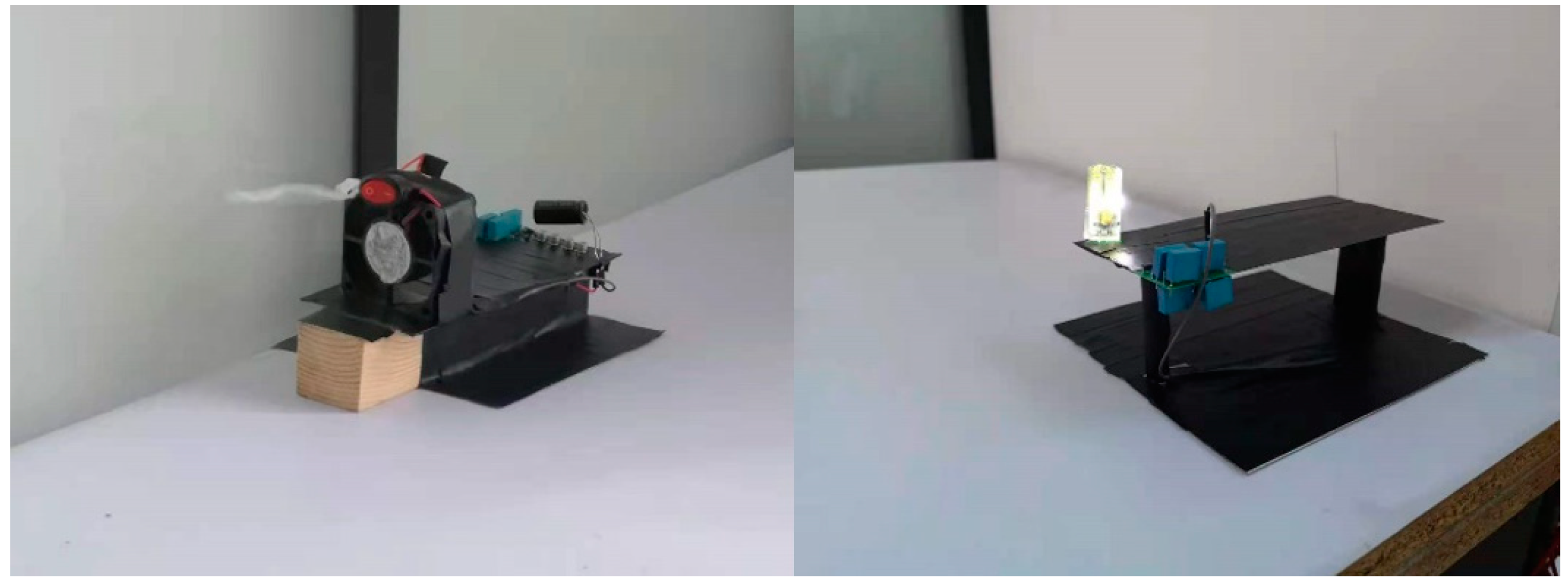
A high-frequency inverter is used to supply power to the desktop wireless power transfer system, and experiments with various forms of load wireless power transfer are shown in
Figure 18. The bottom left of the figure is a high-frequency inverter power supply. Its AC voltage output terminal is connected to the power transfer resonance circuit. The power transfer resonance coil and the high-frequency resonance capacitor resonate to generate a high-frequency distributed electric field on the power supply desktop. The two loads on the desktop are 7 W low-voltage lighting bulbs and 3 W cooling fans. In
Figure 19, both the cooling fan and the light bulb can work normally on the desktop.
Use a DC power supply to provide DC power to the inverter. Set the DC power supply voltage to 20 V and the maximum output current to 2 A. When the inverter operating frequency is 820 kHz, the output current reaches the maximum, and the system works in resonance. Use pointer type DC voltmeter and DC current meter to measure the voltage and current value of the load. The measured DC voltage across the bulb is 10 V, the current flowing through the bulb is 0.4 A, and the bulb power is calculated to be 4 W. The measured DC voltage at both ends of the cooling fan is 20 V, the current flowing through the cooling fan is 0.1 A, and the calculated power of the cooling fan is 2 W. The input power of the power supply is 40 W, the combined load power is 6 W, and the system transmission efficiency is 15%.
According to the experiment and analysis, there are two reasons why the experimental power transmission efficiency of the DWPT system is lower than the theoretical value:
1. The quality factor of resonant coil and resonant capacitor is low. The power transmitting coil is a hand-wound coil, while the power receiving device is a PCB coil. The wire diameter of the coil is small and the distance between turns is narrow, so the proximity effect is more obvious. The resonant capacitor is an ordinary CBB capacitor, which can only meet the capacitance value, and its performance is not good in a high frequency working environment. These reasons cause part of the electrical energy to be converted into heat. The resonant coil and the resonant capacitor generate heat when they work to prove this point. This is the main reason for the reduction in efficiency.
2. The influence of the experimental environment. Due to the limited laboratory space and many metal experimental props in the laboratory, the electric field energy is dissipated. Using metal products of different sizes close to the power supply desktop, the brightness of the bulb will change, indicating that the power supply system will be affected by the surrounding environment.
To solve the problem of low efficiency, the following solutions are proposed: improve the quality factor of resonant capacitors and resonant inductors. Use a thicker wire to wind a larger resonant coil on the power transmitting side and widen the distance between turns of the coil. Use better materials to make the PCB coil on the power receiving side and increase the diameter of the coil. Use better quality high-frequency capacitors as resonant capacitors. Improve the working environment of the system and stay away from large metal equipment.
6. Conclusions and Future Work
This paper proposes a desktop wireless power transfer system based on a high-frequency electric field, establishes a lumped parameter model of the system, simplifies the analysis of the model, and calculates the system’s resonant frequency, resonant capacitance, and resonant inductance parameters, using finite element simulation software to establish the electromagnetic field simulation of the system and analyze the relationship between the operating frequency and output power of the system. An experimental platform for a desktop wireless power transfer system was built, and wireless power transfer experiments for single load, multiple loads, and handheld load were carried out. At the same time, wireless power transfer for cooling fans and lights was realized. Compared with other wireless power transmission systems, the DWPT system has a smaller power receiving device, a wider transmission range and a more flexible transmission method. Among them, the power receiving device is only the size of a mobile phone, and the power supply range can reach 1.2 m2, and the handheld electrical equipment can receive power within a certain range above the desktop. Further work includes theoretical analysis of the electromagnetic field and wireless power transfer of more complex loads, such as wireless power transfer for small electric vehicles and wireless power transfer for smart phones.


