Article

Insulation Monitoring of Dynamic Wireless Charging Network Based on BP Neural Network

1
School of Automation, Nanjing University of Science and Technology, Nanjing 210094, China
2
Maintenance Branch Company, State Grid Jiangsu Electric Power Co., Ltd., Nanjing 211102, China
*
Author to whom correspondence should be addressed.
World Electr. Veh. J. 2021, 12(3), 129; https://doi.org/10.3390/wevj12030129
Submission received: 1 August 2021 / Revised: 10 August 2021 / Accepted: 20 August 2021 / Published: 21 August 2021

Abstract

:
The transmission cable and power conversion device need to be buried underground for dynamic wireless charging of an expressway, so cable insulation deterioration caused by aging and corrosion may occur. This paper presents an on-line insulation monitoring method based on BP neural network for dynamic wireless charging network. The sampling signal expression of the injection signal is derived, and the feasibility of this method is verified by experiments, which effectively overcomes the problem of large calculation error of insulation resistance when the cable capacitance to ground is large. The experimental results indicate that the error of the proposed method is less than 9%, which can meet the needs of insulation monitoring.

1. Introduction

The dynamic wireless charging road can continuously supply the electric energy for driving electric vehicles (EVs), so it has a broad development prospect. The dynamic charging system consists of transmitter and receiver. The receiving end is installed on the driving vehicle, and the transmission end is buried under the road. At present, the dynamic wireless charging technology is mainly divided into track type and segmented type [1]. Taking the segmented type in Figure 1a as an example, the output power of the power grid is converted into DC voltage through the rectifier, and the DC voltage is supplied to the transmitter network of each part through the long horizontal cable, and the converter network of each part is connected in parallel. The cable connecting the transmission end will be aged and corroded because it is buried underground. Long-term use may lead to the deterioration of ground insulation, power cable tripping, equipment damage, and even fire. Therefore, it is necessary to monitor the insulation of these buried cables to avoid huge losses. At present, there are few studies on cable insulation in dynamic wireless charging system. This paper focuses on the insulation monitoring method in ITN system. Generally, the cable insulation monitoring in ITN system is mainly realized by injecting signal, which is divided into DC signal and AC signal [2]. The advantage of injecting DC signal is that when the ground capacitor is fully charged, the calculation results are not affected by the capacitance [3]. The disadvantage is that when the value of the ground capacitor is large, the charging time will be very long, and the current insulation status cannot be analyzed quickly. The injected AC signal is usually a low frequency signal to distinguish it from the power frequency signal. AC injection method is divided into single frequency injection and dual frequency injection. The single frequency injection method needs to obtain the phase information at the same time [4], while the dual frequency injection method needs to generate the dual frequency signal and separate the dual frequency signal [5]. The disadvantage is that when the capacitance to ground is large, the calculation result error is large due to phase error. In addition to the AC injection method, there are other methods, such as adaptive pulse injection, which uses superimposed adaptive pulse voltage signal to detect the fault circuit, and continuously measures the insulation resistance to the ground. The periodic value of the pulse is related to the capacitance to the ground. The larger the capacitance, the longer the period [6]. The disadvantage is that the calculation time is long when the capacitance is large. There are some additional methods for DC power grid, such as bridge balance method, signal tracing method and differential current detection method [7,8,9]. The disadvantage is that it is only for DC power grid and the hardware implementation is complex.
The above calculation methods are more complex, for large ground capacitance and large insulation resistance, it is very difficult to achieve the required calculation accuracy, so many other measures need to be added to maintain the accuracy. In this paper, an insulation monitoring method based on BP neural network is proposed. By learning the signal waveforms at both ends of the sampling resistance after the signal injection, the corresponding relationship between the waveform and the insulation resistance is established to solve the problem of inaccurate calculation of the insulation resistance under the condition of large capacitance (above 100 uF) [10]. We creatively introduce deep learning method into the field of electric vehicle cable insulation monitoring. In order to solve the insulation resistance calculation under large capacitance, the traditional AC injection method can only find ways to improve the phase calculation accuracy. For large capacitance above 100 uF, the phase accuracy must reach 0.1°, which has high requirements for software and hardware. The insulation monitoring method based on BP neural network effectively avoids the problem of high-precision phase calculation, reduces the difficulty of software and hardware design, and ensures the accuracy of insulation resistance calculation.

2. Calculation Model of Insulation Monitoring

As shown in Figure 1b, the model of cable to ground insulation between power grid and transmission unit in highway dynamic wireless charging is proposed. There are capacitance and insulation resistance between cable to ground, which can be equivalent to Cf and Rf in the model. RP1 and RP2 are parasitic resistances on the loop, which are very small and can be ignored in the actual calculation model. R1 is the current limiting resistance, R0 is the sampling resistance, and S1 is the external injection signal used to detect insulation resistance. Through the external injection of a certain frequency signal, the frequency component of the sampling resistance is collected, and then the insulation resistance value of the cable can be obtained through filtering and operation.
If the DC signal with the amplitude of VDC is selected as the injection source and the injection time is t1 in a cycle t0, the injection signal Vs (t) can be expressed as:
V S ( t ) = V D C n = 0 , 1 , 2 . . [ ε ( t n t 0 ) ε ( t n t 0 t 1 ) ]
The current i (t) generated by the injection signal in the loop is as follows, where V0 (t) is the voltage signal at both ends of the sampling resistor:
i ( t ) = V 0 ( t ) R 0
The injection current through the ground capacitance Cf is iCf (t), and the injection current through the insulation resistance Rf is iRf (t). The sum of the two satisfies the following equation:
i ( t ) = i C f ( t ) + i R f ( t )
The injection voltage Vf (t) at both ends of insulation resistance can be expressed as:
V f ( t ) = V S ( t ) V 0 ( t ) ( R 0 + R 1 ) R 0
Then, iCf (t) and iRf (t) can be expressed as:
i C f ( t ) = C f d V f ( t ) d t , i R f ( t ) = V f ( t ) R f
By substituting (2) and (5) into (3), we can get:
C f d V f ( t ) d t + V f ( t ) R f = V 0 ( t ) R 0
It can be further written as:
C f ( R 0 + R 1 ) R 0 V · 0 ( t ) + ( R 0 + R 1 + R f ) R 0 R f V 0 ( t ) = C f V · S ( t ) + 1 R f V S ( t )
After simplification
V · 0 ( t ) + ( R 0 + R 1 + R f ) R f C f ( R 0 + R 1 ) V 0 ( t ) = R 0 R 0 + R 1 V · S ( t ) + R 0 R f C f ( R 0 + R 1 ) V S ( t )
For the convenience of the next calculation, let
a = ( R 0 + R 1 + R f ) R f C f ( R 0 + R 1 ) , b = R 0 R 0 + R 1 , c = R 0 R f C f ( R 0 + R 1 )
Then, (8) can be simplified as
V · 0 ( t ) + a V 0 ( t ) = b V · S ( t ) + c V S ( t )
Substituting (1) into (10), we obtain
V · 0 ( t ) + a V 0 ( t ) = b n = 0 , 1 , 2 . . V D C ( δ ( t n t 0 ) δ ( t n t 0 t 1 ) ) + c n = 0 , 1 , 2 . . V D C ( ε ( t n t 0 ) ε ( t n t 0 t 1 ) )
According to the solution of the first order linear differential equation, it can be concluded that:
V 0 ( t ) = e a t + e a t n = 0 , 1 , 2 . . [ b V D C ( δ ( t n t 0 ) δ ( t n t 0 t 1 ) ) + c n = 0 , 1 , 2 . . V D C ( ε ( t n t 0 ) ε ( t n t 0 t 1 ) ) ] e a t d t
Integrate the two parts of the integral separately; the first term can be reduced to:
n = 0 , 1 , 2 . . b V D C ( δ ( t n t 0 ) δ ( t n t 0 t 1 ) ) e a t d t = b V D C n = 0 , 1 , 2 . . e a t d ( ε ( t n t 0 ) ε ( t n t 0 t 1 ) ) = b V D C n = 0 , 1 , 2 . . e a t ( ε ( t n t 0 ) ε ( t n t 0 t 1 ) ) a b V D C n = 0 , 1 , 2 . . e a t ( ε ( t n t 0 ) ε ( t n t 0 t 1 ) ) d t ] = b V D C n = 0 , 1 , 2 . . e a t ( ε ( t n t 0 ) ε ( t n t 0 t 1 ) ) a b V D C n = 0 , 1 , 2 . . n t 0 n t 0 + t 1 e a t d t = b V D C n = 0 , 1 , 2 . . e a t ( ε ( t n t 0 ) ε ( t n t 0 t 1 ) ) + b V D C n = 0 , 1 , 2 . . ( e a n t 0 e a ( n t 0 + t 1 ) )
The integral result of the second term is the same as that of the above method
c n = 0 , 1 , 2 . . V D C ( ε ( t n t 0 ) ε ( t n t 0 t 1 ) ) ] e a t d t = c a V D C n = 0 , 1 , 2 . . ( e a n t 0 e a ( n t 0 + t 1 ) )
By substituting (13) and (14) into (12), we can find that:
V 0 ( t ) = e a t + e a t [ b V D C n = 0 , 1 , 2 . . e a t ( ε ( t n t 0 ) ε ( t n t 0 t 1 ) ) + ( b c a ) V D C n = 0 , 1 , 2 . . ( e a n t 0 e a ( n t 0 + t 1 ) ) ]
Further, it can be written as:
V 0 ( t ) = { e a t + b V D C + ( b c a ) V D C n = 0 , 1 , 2 . . ( e a n t 0 e a ( n t 0 + t 1 ) ) e a t , n t 0 < t < n t 0 + t 1 e a t + ( b c a ) V D C n = 0 , 1 , 2 . . ( e a n t 0 e a ( n t 0 + t 1 ) ) e a t , n t 0 + t 1 t < ( n + 1 ) t 0
Substituting (9) into (16), the final result is:
V 0 ( t ) = { e ( R 0 + R 1 + R f ) R f C f ( R 0 + R 1 ) t + R 0 R 0 + R 1 V D C + R 0 R f ( R 0 + R 1 + R f ) ( R 0 + R 1 ) V D C n = 0 , 1 , 2 . . ( e ( R 0 + R 1 + R f ) R f C f ( R 0 + R 1 ) n t 0 e ( R 0 + R 1 + R f ) R f C f ( R 0 + R 1 ) ( n t 0 + t 1 ) ) e ( R 0 + R 1 + R f ) R f C f ( R 0 + R 1 ) t , n t 0 < t < n t 0 + t 1 e ( R 0 + R 1 + R f ) R f C f ( R 0 + R 1 ) t + R 0 R f ( R 0 + R 1 + R f ) ( R 0 + R 1 ) V D C n = 0 , 1 , 2 . . ( e ( R 0 + R 1 + R f ) R f C f ( R 0 + R 1 ) n t 0 e ( R 0 + R 1 + R f ) R f C f ( R 0 + R 1 ) ( n t 0 + t 1 ) ) e ( R 0 + R 1 + R f ) R f C f ( R 0 + R 1 ) t , n t 0 + t 1 t < ( n + 1 ) t 0
The above formula is the signal expression of the injection signal contained at both ends of the sampling resistance. It can be clearly seen that the voltage V0 at both ends of the sampling resistor is a periodic signal. There is a difference in DC component between the first half cycle and the second half cycle, and the signal component decays with time in both the first and second half cycles. Generally speaking, it is a relatively complex calculation formula. If it is realized through real-time calculation, the amount of calculation will be very large, Additionally, the expression of Cf must be inversely solved, which is very difficult. Therefore, the method of BP neural network is considered. By learning the waveform of voltage V0 at both ends of the actual sampling resistance, the BP neural network is used to fit the expression (17), and the corresponding relationship between insulation resistance and sampling waveform is established through a large amount of data training. Thus, for a certain V0 waveform, when other variables are determined, there is a certain Rf and Cf corresponding to it, which greatly simplifies the calculation difficulty.

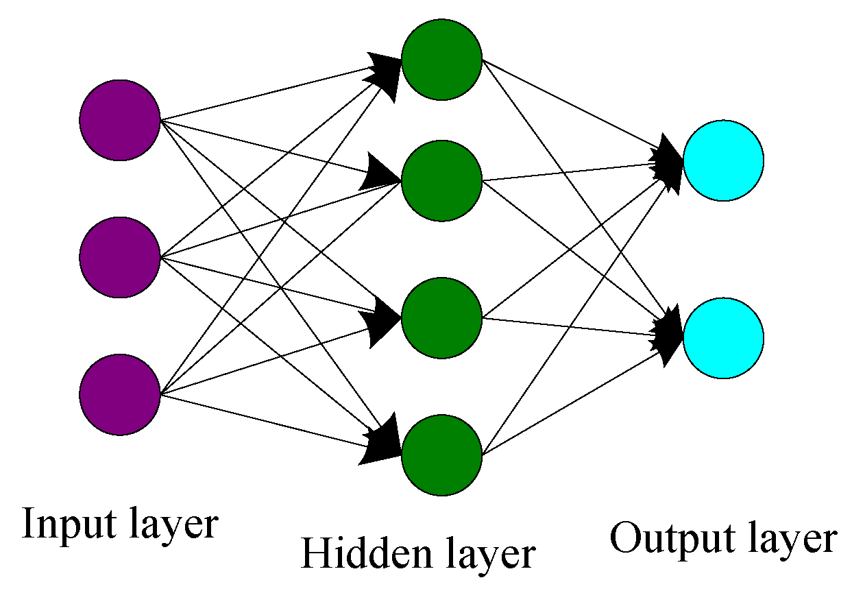
3. Insulation Monitoring Based on BP Neural Network

3.1. Subsection

An insulation monitoring method of wireless charging cable based on BP neural network is proposed. BP neural network is a kind of multilayer feed forward neural network based on error back propagation algorithm, which is the most widely used neural network [11]. BP neural network can establish the corresponding relationship between target and input signal through a lot of data training, especially fitting function curve [12]. BP neural network can be used to predict many nonlinear curves, such as the prediction of power price and power load. Through the training of a large number of targeted data, it can establish a good nonlinear relationship and predict the target trend [13,14]. As shown in Figure 2, it is a typical BP neural network structure, including an input layer, a hidden layer, and an output layer. The input has three nodes, the output has two nodes, and the hidden layer has four nodes. In the actual use process, the number of nodes can be adjusted according to the actual needs. According to the previous calculation principle, the collected signal is periodic charging curve signal, which is very suitable for neural network fitting.

3.1.1. Improvement of BP Neural Network

In addition, the number of hidden layers and the number of neurons in each layer can be increased infinitely, so that the ability of BP neural network has no upper limit. However, it also has some disadvantages, such as slow convergence speed, low accuracy and easy to fall into local minimum. In order to improve the above shortcomings, the learning rate adaptive adjustment function is designed in the process of using.
The learning rate determines the accuracy of network prediction to a certain extent. If the learning rate is too large, the accuracy is poor, or even does not converge. If the learning rate is too small, the convergence is slow. Adaptive adjustment of learning rate is to solve this problem.
If the value E of the error function decreases in this iteration, the learning rate η increases:
η = β · η , β > 1
If the value E of the error function rises in this iteration, the adjustment is invalid and the learning rate η is reduced:
η = α · η , 0 < α < 1
In the actual training process, it is found that when a fixed learning rate is used, if the initial learning rate is large, the initial error often decreases rapidly, but most of the time, the error value stays at a large value and does not decrease. If the initial learning rate is small, the error may always decrease. However, the error reduction rate is significantly less than that in the case of large initial learning rate. After using the adaptive learning rate, it is found that the error can decline all the time, which obviously improves the problem of non-convergence and slow decline of error.

3.1.2. Parameter Design of BP Neural Network

BP neural network parameters mainly include the number of input nodes, the number of hidden layers, the number of output nodes, the number of hidden layer nodes, learning rate and learning accuracy. For function fitting, in theory, BP neural network with only one hidden layer can fit any continuous function. Only when the function is not continuous, the number of hidden layers needs to be increased. However, in fact, the number of hidden layers will affect the speed of fitting convergence, so it should be adjusted according to the actual training process. In addition, the excitation function of the hidden layer will also affect the convergence rate and fitting degree. In this paper, hyperbolic function is selected as the excitation function, as shown in Equation (20).
f ( x ) = 2 1 + ( e 2 x ) 1
After actual test and adjustment, the final parameters of BP neural network are shown in Table 1.

3.2. Neural Network Training Process

According to the previous calculation principle, we need to inject a certain signal into the cable, and realize the calculation of insulation resistance by learning the waveform of sampling signal. The calculation results need to be updated in real time, so constant DC signal cannot be injected. On the other hand, in order to improve the waveform difference under different resistance and capacitance conditions and improve the accuracy of the calculation results, it is necessary to increase the injection time of the injection signal appropriately. In this paper, a DC injection source with 24 V amplitude is selected, which is injected for 26 s, turned off for 9 s and injected for the next cycle. A total of 200 groups of sampling voltage values under different combinations of grounding capacitance and insulation resistance are collected. These sampling values and corresponding insulation resistance values are used as training data. As shown in Figure 3, partial sampling data values, different combinations of resistance and capacitance correspond to different curves. After 3,000,000 training times, the expected accuracy is achieved. As shown in Figure 4, the curve of error decrease in the process of training.

4. Simulation and Analysis

4.1. Build the Actual Experimental Circuit

As shown in Figure 5, metal film resistance is used to simulate insulation resistance, polypropylene film capacitance is used to simulate ground capacitance, and air switch is used to switch capacitance. The insulation measuring device is made with stm32f407 chip of ST company as the core. The insulation resistance is calculated with the insulation measuring device. The right side of Figure 5 is the voltage waveform of the sampling resistance when the resistance is 6 MΩ and the capacitance to ground is 100 uF.

4.2. Recognition Results

As shown in Table 2, different combination values of insulation resistance and ground capacitance are set, and nine groups of insulation resistance values are obtained. The errors between the calculated values and the theoretical values of nine groups were less than ±9%. Because this method is realized by learning curve of BP neural network, the insulation resistance value can be calculated accurately in the case of large capacitance to ground, which effectively overcomes the problem of large error of direct calculation result in large capacitance.

5. Conclusions

Based on the insulation monitoring method described above, this paper builds the corresponding experimental platform, uses farad capacitance and metal film resistance to simulate the value of ground capacitance and insulation resistance, and randomly generates nine groups of different combinations of ground capacitance and insulation resistance to carry out the experiment. The experimental results are shown in Table 2, and the accuracy of nine groups of calculation results can be maintained within the error range of 9%, which can be realized accurate judgment of insulation condition achieves the initial purpose.
Through the experimental data, it is obvious that the method proposed in this paper can still maintain high accuracy in the case of large capacitance above 100 uF, or the case of large capacitance is a special case for the traditional AC injection method, which requires additional hardware and software design to ensure the phase accuracy and calculation accuracy. However, there is no obvious difference between large capacitance and small capacitance for the calculation method proposed in this paper. It does not need to be treated differently, which breaks through the technical bottleneck of traditional methods and greatly reduces the difficulty of hardware design. The calculation method of insulation resistance proposed in this paper can be applied to highway dynamic wireless charging, parking lot static wireless charging and other applications involving underground cables.

Author Contributions

F.W. conceived and designed the study; this work was performed under the advice of and regular feedback from him. W.P. and Q.L. were responsible for the models and simulations. W.P. wrote the article. Z.C. and W.Z. were responsible for the experiments. S.W., X.Z. and C.H. were responsible for the data analysis. All authors have read and agreed to the published version of the manuscript.

Funding

This work was Funded by China Postdoctoral Science Foundation (2020M671498), the Basic Research Program of Jiangsu Province (BK20180485), the Fundamental Research Funds for the Central Universities (30919011241), the Jiangsu Planned Projects for Postdoctoral Research Funds (2020Z374) and the Science and Technology Project of State Grid Jiangsu Electric Power Co., Ltd. (J2020135, SGJSJX00BGJS2002373).

Conflicts of Interest

The authors declare no conflict of interest. The funders had no role in the design of the study; in the collection, analyses, or interpretation of data; in the writing of the manuscript; or in the decision to publish the results.

References

  1. Su, H.; Zhou, Z.; Liu, Z.; Zhang, L. Research review and prospect of intelligent dynamic wireless charging system for electric vehicles. Chin. J. Intell. Sci. Technol. 2020, 2, 1–9. [Google Scholar]
  2. Wang, W.; Yang, T.; Shao, X.; Qiang, L.V.; Song, P. Study on insulation monitoring of low voltage it system based on injection signal. Electrotech. Electric. 2012, 49–55. [Google Scholar]
  3. Li, C. Analysis on online supervision system of high voltage cable insulation condition of coal mine. Mech. Manag. Dev. 2016, 31, 70–86. [Google Scholar]
  4. Yu, S.; Zeng, T.; Li, Y.; Hu, Y.; Liu, L.; Wen, J.; Liu, H.; Wang, X. Design of insulation monitoring device based on improved single frequency method. China Meas. Test. 2020, 46, 78–82. [Google Scholar]
  5. Hu, Y.; Zeng, T.; Li, Y.; Yu, S.; Liu, L.; Wen, J.; Liu, H.; Wang, X. Design of insulation monitoring device based on improved dual frequency injection method. Instrum. Tech. Sens. 2020, 47–51. [Google Scholar]
  6. Wang, X. Application of low voltage insulation monitoring and fault location system based on AMP measurement method. Electr. Eng. 2020, 49–51. [Google Scholar] [CrossRef]
  7. Yu, H.; Jiao, S.; Yang, F. Design of insulation monitoring equipment for direct current network in ship. Chin. J. Ship Res. 2010, 5, 56–58. [Google Scholar]
  8. Li, L.; Zou, J.; Sun, H. Research and realization the DC system grounding fault detector. In Proceedings of the 6th International Symposium on Test and Measurement, Dalian, China, 1–4 June 2005; p. 7444. [Google Scholar]
  9. Wu, Z.; Wang, L. Research on intelligent on-line insulation monitoring device for electric vehicle. Low Volt. Appar. 2009, 20–22. [Google Scholar]
  10. Zhang, J.; Li, S.; Qi, K.; Wang, C.; Zhang, Q.; Huang, H. On line insulation impedance monitoring and fault location of ITN shore power system based on AC injection method. Mar. Electr. Electron. Eng. 2020, 40, 19–25. [Google Scholar]
  11. Makarenko, A. Multiple-valued and branching neural networks. Eng. World 2020, 2, 20–28. [Google Scholar]
  12. Al-Mawsawi, S.A.; Haider, A.; Alfaris, Q. Neural Network Model Predictive Control (NNMPC) Design for UPFC. WSEAS Trans. Comput. 2020, 19, 201–207. [Google Scholar] [CrossRef]
  13. Wang, L.; Zhang, Q. Short term power load forecasting of regional distribution network based on BP neural network. Softw. Dev. 2021, 49–52. [Google Scholar] [CrossRef]
  14. Wang, M.; Jing, Z.; Sun, B. Prediction of short-term market clearing price based on BP neural network. China Electr. Power Educ. 2011, 100–102. [Google Scholar] [CrossRef]
Figure 1. (a) Dynamic wireless charging network model for highway. (b) Calculation model of cable to ground insulation resistance in dynamic wireless charging network.
Wevj 12 00129 g001
Figure 2. Typical BP neural network structure.
Wevj 12 00129 g002
Figure 3. Sampling voltage values of different combinations of capacitance and insulation resistance under injection signal.
Wevj 12 00129 g003
Figure 4. Error evolution curve of BP neural network.
Wevj 12 00129 g004
Figure 5. The left side is the cable insulation resistance measurement experiment, and the right side is the waveform of sampling resistance at both ends when Rf = 6 MΩ and Cf = 100 uF.
Wevj 12 00129 g005
Table 1. Parameters of BP neural network.
Parameter NameParameter Value
Number of input nodes1
Number of output nodes1
Number of hidden layers4
Number of hidden layer nodes(50, 50, 50, 50)
Initial learning rate0.001
Learning accuracy0.000001
Training times3000000
Table 2. Experimental results.
Analog Value of Capacitance to GroundTrue Value of Insulation ResistanceCalculated Insulation Resistance ValueError Value
253 μF2.616 kΩ2.791 kΩ+6.68%
388 μF12.31 kΩ13.402 kΩ+8.87%
387 μF85.627 kΩ89.737 kΩ+4.80%
63 μF599.73 kΩ598.83 kΩ−0.15%
491 μF174.96 kΩ184.92 kΩ+5.69%
350 μF732.31 kΩ756.22 kΩ+3.27%
123 μF1.462 MΩ1.496 MΩ+2.33%
37 μF8.897 MΩ9.041 MΩ+1.62%
260 μF5.006 MΩ5.103 MΩ+1.93%
Publisher’s Note: MDPI stays neutral with regard to jurisdictional claims in published maps and institutional affiliations.

