Article

Study on the Stability Control of Vehicle Tire Blowout Based on Run-Flat Tire

1
Nanjing Institute of Technology, School of Automobile and Rail Transportation, Nanjing 211167, China
2
College of Energy and Power Engineering, Nanjing University of Aeronautics and Astronautics, Nanjing 210016, China
*
Author to whom correspondence should be addressed.
World Electr. Veh. J. 2021, 12(3), 128; https://doi.org/10.3390/wevj12030128
Submission received: 28 July 2021 / Revised: 12 August 2021 / Accepted: 20 August 2021 / Published: 21 August 2021

Abstract

:
In order to study the stability of a vehicle with inserts supporting run-flat tires after blowout, a run-flat tire model suitable for the conditions of a blowout tire was established. The unsteady nonlinear tire foundation model was constructed using Simulink, and the model was modified according to the discrete curve of tire mechanical properties under steady conditions. The improved tire blowout model was imported into the Carsim vehicle model to complete the construction of the co-simulation platform. CarSim was used to simulate the tire blowout of front and rear wheels under straight driving condition, and the control strategy of differential braking was adopted. The results show that the improved run-flat tire model can be applied to tire blowout simulation, and the performance of inserts supporting run-flat tires is superior to that of normal tires after tire blowout. This study has reference significance for run-flat tire performance optimization.

1. Introduction

As an important part of the vehicle driving system, tires are the only direct contact part between the vehicle and the road surface. The main functions are to support the vehicle, mitigate the impact of the road surface, and generate braking force, which have an important impact on comfort and other aspects of performance of the vehicle [1]. According to statistics, 46% of traffic accidents on expressways are caused by tire failures, and a flat tire alone accounts for 70% of the total tire accidents [2].
How to improve the stability of vehicles after tire blowout has always been the core problem of domestic and foreign scholars. CHEN set up an estimated calculation model of additional yaw torque leading by tire blowout based on Dugoff tire model [3]. LI proposed a modified linear time-varying model predictive control (LTV-MPC) method based on the Pacejka tire model, and the stability region of the vehicle with active front steering was expanded [4]. LIU established an extended three-degree of freedom model considering longitudinal velocity to weaken the influence of the steering wheel angle under extreme conditions [5]. CHEN proposed a comprehensive coordinated control scheme for longitudinal and lateral stability based on the brush tire model. Speed tracking under the limit speed is achieved by means of longitudinal acceleration feedforward and state feedback controller [6]. GUO established a tire model suitable for operating coach and estimated the sideslip angle, as well as the yaw rate of the operating coach in real time based on the extended Kalman filter state estimator [7].
In addition, some scholars have done a lot of research on the stability control after tire blowout. LIU proposed a fuzzy sliding mode control algorithm based on the current tire blowout control algorithm, and the tire blowout model is established using the UniTire model [8]. JING established a linear variable parameter vehicle model considering the time-varying speed and the uncertainty of tire characteristics [9]. WANG proposed a coordinated control approach based on active front steering and differential braking. The model predictive control method was adopted to control the front wheel angle for tracking the trajectory, and the differential brake control was adopted to offer an inner-loop control input and improve the lateral stability [10]. CHEN established the kinematics equation of the vertical load of the vehicle after tire blowout according to the vehicle dynamics model and the displacement mutation in the vertical direction of the tire wheel center [11]. ERLIEN found that the mandatory implementation of stability constraints may conflict with the expected collision avoidance trajectory and proposed that the stability controller should allow the vehicle to run outside the stability constraints to achieve safe collision avoidance [12]. WANG proposed a novel linearized decoupling control procedure with three design steps for a class of second order multi-input-multi-output non-affine system [13]. YANG proposed a composite stability control strategy for tire blowout electric vehicle with explicit consideration of vertical load redistribution [14]. CHOI designed a layered lateral stability controller based on LTV-MPC. The nonlinear characteristics of the tire are reflected in the extended “bicycle” model by continuously linearizing the tire force [15]. WANG proposed a nonlinear coordinated motion controller in the framework of the triple-step method to solve the path-following and safety problem of road vehicles after a tire blowout [16].
However, the tire blowout condition of the vehicle equipped with run-flat tire is more complicated, and there is no model that can be directly applied to inserts supporting run-flat tire under tire blowout condition. In addition, the inserts supporting run-flat tire is a typical run-flat tire based on the pneumatic tire structure, which consists of an auxiliary support body on the rim and a tire pressure detection device [17]. Because this type of run-flat tire is mostly based on the common rim design, it has the advantages of simple structure, convenient disassembly, strong zero-pressure bearing capacity, and so on. It is a new type of run-flat tire with great development prospects. In order to study the stability of the vehicle with inserts supporting run-flat tire after blowout, a dynamic model was established and modified based on the UniTire model. Afterwards, the model was modified according to the discrete curve of tire mechanical properties under steady conditions. The results show that the improved run-flat tire model is consistent with the characteristics of vehicle tire blowout, and the optimal control strategy of inserts supporting run-flat tire after blowout in straight running condition was obtained by comparing the effects of braking, steering, and combined control.

2. Establishment of Run-Flat Tire Model

2.1. Run-Flat Tire Model before Blowout

The performance of inserts supporting run-flat tire is the same as that of a normal tire before tire blowout. Therefore, the model of inserts supporting run-flat tire is established according to the UniTire [18] theory and the published test data, which mainly analyse the parameters of the mechanical properties in the process of tire blowout.
The longitudinal slip ratio and lateral slip ratio are defined as the ratio of slip velocity to rolling velocity. The definition is as follows:
{ S x = V s x Ω R e = Ω R e V x Ω R e , S x ( , + ) S y = V s y Ω R e = V y Ω R e , S y ( , + )
where  Sx is the longitudinal slip ratio;  Sy is the lateral slip ratio; Ω is the tire rolling angular velocity; Re is the effective rolling radius; Vx and V y are the longitudinal and lateral components, respectively, of the wheel center velocity V.
The normalized longitudinal slip ratio ϕ x , normalized lateral slip ratio ϕ y , and total slip ratio ϕ are defined as dimensionless physical quantities.
{ ϕ x = K x S x μ x F z ϕ y = K y S y μ y F z ϕ = ϕ x 2 + ϕ y 2
where K x is the longitudinal slip stiffness of the tire; K y is the cornering stiffness of the tire; µ x is the longitudinal friction coefficient between tire and ground; µ y is the lateral friction coefficient between tire and ground; and Fz is the tire vertical force.
The total tangential force expression of the complete E-index semi-empirical model is as follows:
F ¯ = 1 exp [ ϕ E 1 ϕ 2 ( E 1 2 + 1 12 ) ϕ 3 ]
where E 1 is the curvature factor.
The aligning arm Dx of the steady semi-empirical model can be expressed as follows:
D x = ( D x 0 + D e ) exp ( D 1 ϕ D 2 ϕ 2 ) D e
where D x 0 is the initial aligning arm; D e is the final value of the aligning arm; D 1 is the first order curvature factor; and D 2 is the quadratic curvature factor.
According to the above theoretical model, the tire aligning torque can be obtained as follows:
M z = F y ( D x + X c ) F x Y c
where X c and Y c are the offset caused by longitudinal force and lateral force, respectively.
The formula of tire rolling resistance moment My is as follows:
M y = ( R r _ c + R r _ v V r ) F z R l
where R r _ c is the rolling resistance coefficient; R r _ v is the rolling resistance speed constant of the tire; Vr is the longitudinal velocity of wheel center ( V r = Ω R e ); and R l is the load radius of the tire.

2.2. Run-Flat Tire Model after Blowout

During the process of tire blowout, the vehicle is extremely unstable and the tire burst time is short. In order to simplify the model, the parameters of the tire are linearized [19]. According to the experiment of the mechanical properties of the tire blowout, it can be seen that the longitudinal slip stiffness, lateral deflection stiffness, and effective rolling radius of the tire are reduced to 28%, 25%, and 80% of the normal working conditions, respectively, and the rolling resistance coefficient of the tire increases by 30 times [20].
However, the above data cannot be fully applied to the inserts supporting run-flat tire. In order to study the parameter changes of the inserts supporting run-flat tire after tire blowout, the corresponding curves under the working conditions were obtained using the test bench.

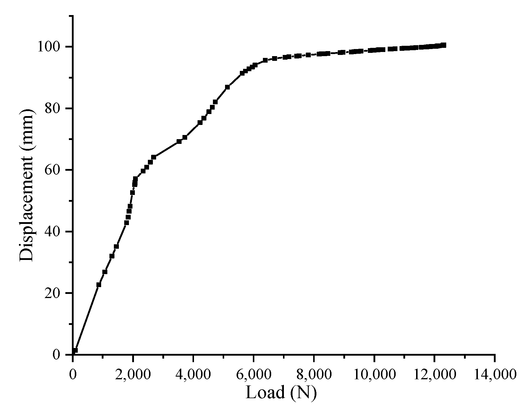
2.2.1. Cornering Stiffness and Longitudinal Stiffness after Tire Blowout

In order to simplify the research, the static loading method was used to analyse the longitudinal and lateral mechanical characteristics of inserts supporting run-flat tire at zero-pressure. The tire size is 37 × 12.5R16.5. The relationship curves of tire lateral force and sideslip angle, longitudinal force, and longitudinal displacement under different loads are obtained, as shown in Figure 1.
It can be seen from Figure 1a that the sideslip angle of inserts supporting run-flat tire under zero-pressure condition is 1.8 deg. At this time, the lateral force is about 4700 N. The critical point of sideslip is selected to calculate the stiffness. The slope at this point is approximately equivalent to cornering stiffness and the cornering stiffness is about 1.48 × 10⁵ N/rad (4700 N/1.8 deg), which is about 0.90 times the rated tire pressure condition. Similarly, it can be seen from Figure 1b that the longitudinal stiffness becomes about 0.95 times.
It can be concluded that the cornering stiffness will be reduced to about 90% of the normal tire pressure condition and the longitudinal stiffness will be reduced to about 95% after inserts supporting run-flat tire blowout.
Therefore, the changes of longitudinal and cornering stiffness during tire blowout can be expressed as follows:
{ K x = ( 0.95 K x 0 K x 0 ) T d ( T T s ) + K x 0 K y = ( 0.90 K y 0 K y 0 ) T d ( T T s ) + K y 0
where K x 0 is the longitudinal stiffness before tire blowout; K y 0 is the cornering stiffness before tire blowout; T d is the duration of tire blowout; T s is the time of tire blowout; and T is the simulation time.

2.2.2. Change of Rolling Resistance Coefficient after Tire Blowout

The rolling resistance coefficient is the ratio of the required thrust to the wheel load when the wheel is rolling under certain conditions. The increase in the tire contact area after tire blowout is the main factor of the rolling resistance change. The dimension parameters of the contact impression of the inserts supporting run-flat tire were extracted under zero-pressure condition and rated load, as shown in Table 1 and Figure 2.
It can be seen from Figure 2 that the green frame is the shoulder part, and the red frame is the tire part with insert. Under the zero-pressure condition, the insert takes part in the load-bearing, and the colour of the tire shoulder is lighter where it is affected by the insert. The increase of rolling resistance after tire blowout is mainly caused by the increase of contact area between elastic rubber and ground. The rolling resistance of a normal tire increases 30 times after tire blowout. Compared with inserts supporting run-flat tire, the inserts are in direct contact with the tire and the rolling resistance of this contact area is affected after tire blowout. Hence, the rolling resistance affected by insert is approximately equivalent to the rolling resistance of the rated tire pressure and the contact area of insert is about 25% of the whole contact area from Table 1. The rolling resistance of the rest areas is 30 times of the normal tire pressure; therefore, the rolling resistance of inserts supporting run-flat tire under the zero-pressure condition is about 22.8 (0.25 + 0.75 × 30) times of that under the normal condition.
Therefore, the change of rolling resistance coefficient during tire blowout can be expressed as follows:
R r _ c = ( 22.8 R r _ c 0 R r _ c 0 ) T d ( T T s ) + R r _ c 0
where R r _ c 0 is the rolling resistance coefficient before tire blowout.

2.2.3. Change of Effective Rolling Radius after Tire Blowout

Effective rolling radius refers to the vertical distance from the tire rolling center to the ground under a certain load when the tire is rolling steadily. The load characteristic curve of inserts supporting run-flat tire under zero pressure condition was extracted, as shown in Figure 3.
As can be seen from Figure 3, the tire displacement under the zero-pressure is 100.36 mm, and the tire rolling radius and load radius under the rated load are 455 mm and 467 mm, respectively. Hence, the rolling radius of the inserts supporting run-flat tire is about 0.92 times the normal rolling radius.
The change in effective rolling radius during tire blowout can be expressed as follows:
R e = ( 0.92 R e 0 R e 0 ) T d ( T T s ) + R e 0
where R e 0 is the effective rolling radius before tire blowout.

3. Two Degrees of Freedom Model and Control System

3.1. Two Degrees of Freedom Model

When a tire blowout occurs, the control system needs to determine the additional yaw moment and the additional active angle according to the deviation between the actual driving state and the ideal driving state, so as to keep the vehicle in the driving state before the tire blowout. At the same time, in order to facilitate the analysis of the relationship between the vehicle motion state and stability, the vehicle model is simplified, and the vehicle two degrees of freedom control model is used as the ideal vehicle motion model.
The ideal expression of the two degrees of freedom model is as follows:
{ m V x ( β ˙ + r ) = ( C f + C r ) β ( a C f b C r ) V x r + C f δ I z r ˙ = ( b C r a C f ) β ( a 2 C f + b 2 C r ) V x r + a C f δ + Δ M z
Considering the influence of the additional yaw moment acting on the vehicle, the above formula is transformed into the equation of state:
[ β ˙ r ˙ ] = [ a 11 a 12 a 21 a 22 ] [ β r ] + [ b 1 b 2 ] δ + [ c 1 c 2 ] Δ M z
where [ a 11 a 12 a 21 a 22 ] = [ ( C f + C r ) m V x b C r a C f m V x 1 b C r a C f I z b 2 C r + a 2 C f I z V x ] ; [ b 1 b 2 ] = [ C f m V x a C f I z ] ; [ c 1 c 2 ] = [ 0 1 I z ] ; Vx is the velocity of the vehicle along the x-axis; m is the total mass of the vehicle; β is the sideslip angle; r is the yaw rate; δ is the front wheel angle; a and b are the distances from the mass center to the front and rear axles, respectively; Iz is the moment of inertia of the whole vehicle around the z-axis; and Cf and Cr are equivalent cornering stiffness of front axle and rear axle, respectively.
The yaw rate under ideal stable state is as follows:
r d = V x L ( 1 + K V x 2 ) δ
where L is the axis between the front and rear wheels distance.
The expression of vehicle stability coefficient K is as follows:
K = m L 2 ( a C r b C f )
The modified expression of ideal yaw angle is as follows:
r d * = min { | V x L ( 1 + K V x 2 ) δ | , | μ g V x | } sgn ( δ )
where rd is the ideal yaw rate; r d * is the ideal yaw rate after correction; μ is the adhesion coefficient of pavement; and g is the acceleration of gravity.
The ideal sideslip angle of the mass center is corrected as follows:
{ β d = b m a V x 2 C r L L ( 1 + K V x 2 ) δ β d max = μ g V x 2 ( b m a V x 2 C r L ) β d * = min { | b m a V x 2 C r L L ( 1 + K V x 2 ) δ | , | μ g V x 2 ( b m a V x 2 C r L ) | } sgn ( δ )
where β d * is the corrected ideal sideslip angle of mass center and β d , β d max is an intermediate variable.

3.2. Differential Braking Control System

The fuzzy sliding mode control algorithm is used to control the yaw moment after tire blowout, and the yaw moment is distributed to each wheel through the principle of braking force distribution, so as to control the stability of the vehicle.
According to the comparison between the ideal yaw rate and sideslip angle of mass center and the actual one, the switching function of the sliding surface is selected. The expression is as follows:
s = ( r r d ) + ε ( β β d )
where r is the yaw rate of the vehicle and rd is the ideal yaw rate of the vehicle; β is the sideslip angle of mass center; and ε is the weighting coefficient.
The controller output yaw moment is as follows:
Δ M z 1 = I z [ r ˙ d + ε β ˙ d ( a 21 + ε a 11 ) β ( a 21 + ε a 11 ) r ( b 2 + ε b 1 ) δ k s a t ( s τ ) ]
where s a t ( s τ ) is the saturation function.
In the process of tire blowout, the sideslip stiffness of tire blowout does not change linearly, so it is difficult to determine the magnitude of the compensated yaw moment, and the fuzzy controller is selected to compensate the yaw moment. In the design of the Simulink fuzzy toolbox, the “Mamdain” method is selected as the fuzzy controller.
The two-dimensional structure was adopted in the fuzzy controller, that is, the input value is the difference of the sideslip angle of the mass center Δ β and the yaw rate Δ r , and the output value of the fuzzy controller is set to U. The basic domain of Δ β is [–5,5]. The basic domain of Δ r is [–1.5,1.5] and that of U is [–20,20]. The membership function of the fuzzy controller is selected as the Gauss membership function. Fuzzy control rules are shown in Table 2.
According to the fuzzy control algorithm, it can be known that the relationship of the compensated yaw moment obtained by maintaining the stability of the vehicle is as follows:
Δ M z 2 = K 1 U
where Δ M z 2 is the compensated yaw moment.
Therefore, the yaw moment to maintain the stability of the vehicle in the process of tire blowout is as follows:
Δ M z = Δ M z 1 + Δ M z 2
Considering the influence of tire blowout on vehicle stability, the tire without blowout is preferred in the braking force distribution strategy. After the master-slave braking tire is determined, the braking force is determined according to the yaw moment, so as to keep the vehicle stable.

4. Simulation Results and Test Analysis

E-class SUV is selected as the basis of vehicle dynamics simulation model in CarSim, as shown in Table 3. The vehicle two degrees of freedom model is the basis of stability control. It describes the effects of yaw rate and sideslip angle of the mass center on vehicle yaw and lateral motion. In order to simplify the model analysis, it is taken as the ideal vehicle motion model.
In order to study the characteristics of the inserts supporting run-flat tire, the UniTire tire model was built in Simulink. Based on CarSim, the simulation of run-flat tire blowout was carried out under the straight driving condition. The tire blowout parameters of the front and rear wheels on the same side were extracted and compared with the normal tire. The tire size is 37 × 12.5R16.5 and the outer diameter of the insert is 840 mm.

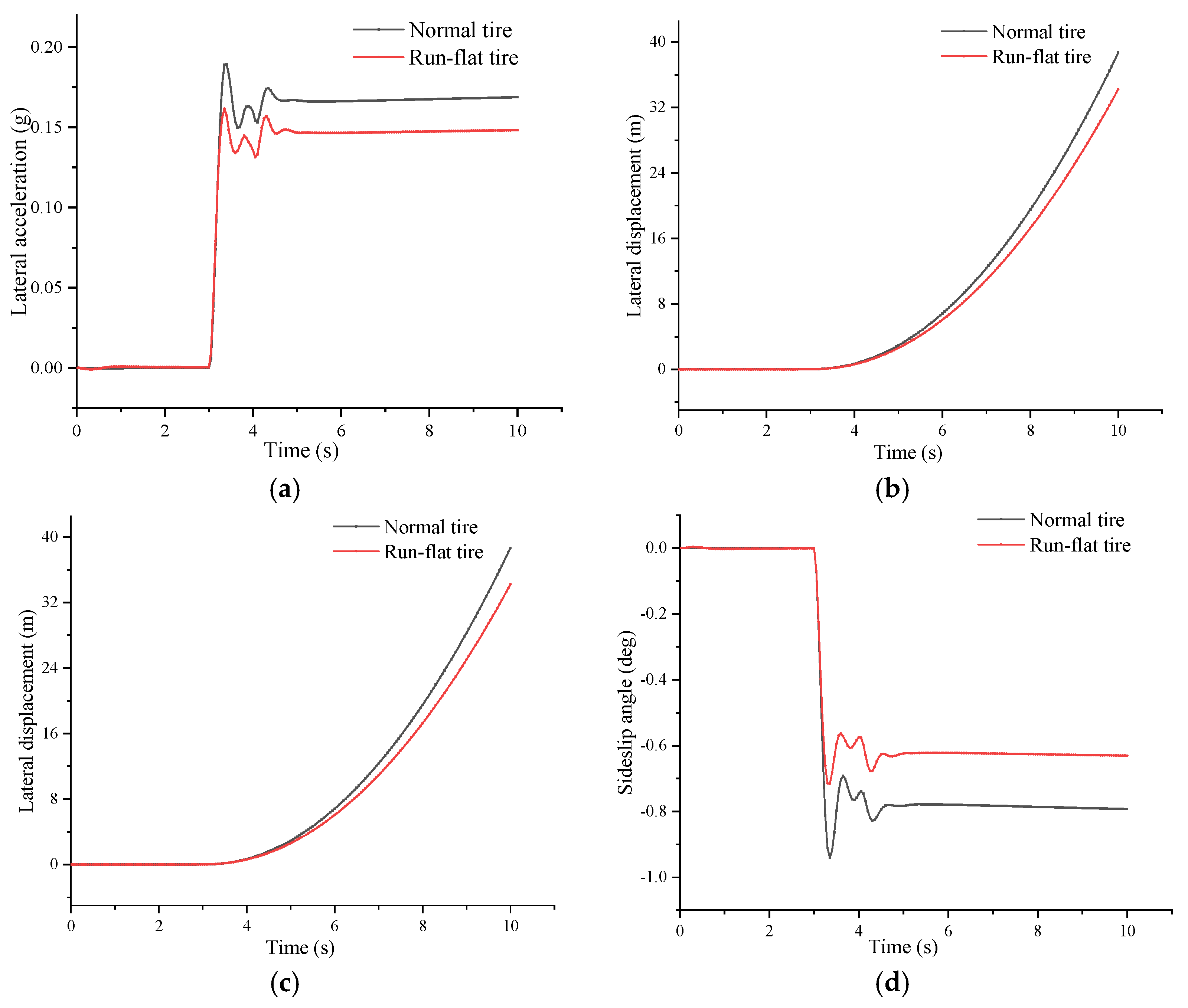
4.1. Tire Blowout Dynamic Response

When the vehicle runs in the straight running condition, the setting speed is 100 km/h, and the road adhesion coefficient is 0.85. In order to simplify the analysis, the left front wheel and the left rear wheel were selected to carry out the tire blowout test, respectively, and the difference between the inserts supporting run-flat tire and the normal tire in the uncontrolled state were compared after the tire blowout.
(1)
Left front tire blowout
When the vehicle is running in the straight running condition, the left front wheel suddenly blows out in the third second. The driver does not take any operation during the tire blowout, and the running state of the vehicle was obtained. The change chart of tire blowout parameters is shown in Figure 4.
It can be seen from Figure 4 that the characteristics of the inserts supporting run-flat tire blowout are similar to the normal tire under the straight driving condition. From Figure 4a,b, it can be seen that the lateral acceleration and lateral displacement of the inserts supporting run-flat tire are slightly larger than the normal tire, and the lateral displacement reaches 75 m in 10 s. Figure 4c,d indicate that the parameter change is unstable in the first two seconds of tire blowout; the yaw rate and the sideslip angle change sharply, then gradually stabilize in about fifth second.
(2)
Left rear tire blowout
When the vehicle runs normally in a straight line, the left rear tire blows out in the third second, and the driver still does not take any measures. The simulation results are shown in Figure 5.
It can be seen from Figure 5 that the rear tire blowout yaw of the inserts supporting run-flat tire is smaller than that of the normal tire, and the curve is obviously better than that of the front tires. This is because the engine of the model selected is front-mounted, so the vertical load on the front axle is larger than that of the rear axle. When tire blowout occurs, the rolling resistance increases, and the front tire is generally the driving wheel, which makes the force on both sides of the wheels uneven, forcing the car to lean to the side of the tire blowout.

4.2. Stability Control Analysis

In order to study the change of the stability parameters of the inserts supporting run-flat tire after the tire blowout, differential braking control is applied to the left front tire and the left rear tire, respectively. The running speed of the vehicle is 100 km/h, and the road adhesion coefficient is 0.85. In the third second, tire blowout occurs. The state of the vehicle is shown in Figure 6 and Figure 7, respectively.
(1)
Left front tire control results
As can be seen from Figure 6, the yaw state of the inserts supporting run-flat tire is obviously improved after applying the differential braking control, and the deviation from the original track under the control effect of lateral displacement is less than 3 m; the change of yaw rate and sideslip angle is obviously reduced under the control effect. The maximum value of yaw rate after correction is 1.8 deg/s, and the maximum deviation of sideslip angle after correction is about 1.2 deg. However, the direction of the sideslip angle of the inserts supporting run-flat tire is opposite to that before control.
(2)
Left rear tire control results
It can be seen from Figure 7 that the left rear tire can basically follow the normal driving track, and the lateral displacement is about 0.25 m under the differential braking control. The lateral acceleration and yaw rate are close to the norm, and the fluctuation is small. At 4 s, they can basically return to the normal state. Therefore, the stability of the vehicle with control after tire blowout is obviously improved compared with that without control.

5. Conclusions

The tire blowout model of inserts supporting run-flat tire is built based on the UniTire theory. Combined with the whole vehicle model built by CarSim, the co-simulation is carried out to obtain the change in characteristic parameters under the straight driving condition.
(1)
The difference between the left front tire and left rear tire blowout condition of inserts supporting run-flat tire and normal tire was compared. The results show that the characteristic parameters of the two tires are similar. When the front tire blowout occurs, the yaw of the inserts supporting run-flat tire is larger, and when the rear tire blowout occurs, the yaw of the normal tire is larger.
(2)
The stability of the inserts supporting run-flat tire after tire blowout is controlled according to the difference between the ideal yaw rate and the sideslip angle and the actual value. The simulation results show that the differential braking control can better maintain the running track of the vehicle, significantly improve the stability of the vehicle, and whether the track adjustment effect of the rear tire of inserts supporting run-flat tire is better.

Author Contributions

X.W. performed the data analyses and wrote the manuscript; L.Z. contributed to the conception of the study; Z.W. performed the experiment; Fen Lin contributed significantly to analysis and manuscript preparation; Z.Z. helped perform the analysis with constructive discussions. All authors have read and agreed to the published version of the manuscript.

Funding

This research was partly supported by the National Natural Science Foundation of China under grant 51605215, and partly by the China Postdoctoral Science Foundation under grant 2019T120450, the Qing Lan Project (Teacher Su 2019 [3]), Research Foundation of Nanjing Institute of Technology (grant number. CKJA201906).

Conflicts of Interest

The authors declare no conflict of interest.

References

  1. Huang, J.; Guo, K.; Song, X.; Liu, W. Vehicle stability control method after tire blow-out. China Mech. Eng. 2009, 20, 2006–2010. [Google Scholar]
  2. Liu, Y.; Yu, S.Y.; Gu, X.L. Trajectory control of vehicles with blowout tire on expressway based on fuzzy PID algorithm. J. Jilin Univ. Inf. Sci. Ed. 2015, 33, 380–388. [Google Scholar]
  3. Chen, Q.; Li, X.; Guo, L.; He, R. Research on estimated calculation model of additional yaw torque after vehicle tire blow-out. China Mech. Eng. 2014, 25, 422–425. [Google Scholar]
  4. Li, S.; Guo, K.; Chou, T. Stability control of vehicle with active front steering under extreme conditions. Automot. Eng. 2020, 42, 191–198. [Google Scholar]
  5. Liu, P.; Sun, L.; Yang, M.; Yuan, F. Research on ideal vehicle reference model for yaw stability control. J. Chongqing Univ. Technol. Nat. Sci. 2020, 34, 17–24. [Google Scholar]
  6. Chen, L.; Xie, Y.; Cai, Y.; Sun, X.; Teng, C.; Zhou, K. Stable tracking control of autonomous vehicles at extreme conditions. Automot. Eng. 2020, 42, 1016–1026. [Google Scholar]
  7. Guo, Y.; Lu, Y.; Fu, R.; Yang, F. Simulation and analysis of lateral stability of large coach. China J. Highw. Transp. 2018, 31, 156–164. [Google Scholar]
  8. Liu, W.; Zhang, X. Study on fuzzy sliding mode control algorithm of vehicle stability control after a tire blowout. Mech. Sci. Technol. Aerosp. Eng. 2019, 38, 1944–1953. [Google Scholar]
  9. Jing, H.; Liu, Z. Gain-scheduling robust control for a tire-blow-out road vehicle. J. Automob. Eng. 2019, 233, 344–362. [Google Scholar] [CrossRef]
  10. Bai-Nan, L.; Hong-Yan, G.; Hong, C. Trajectory tracking and stability control for vehicle after tire blow-out. Electr. Mach. Control 2013, 17, 97–104. [Google Scholar]
  11. Chen, D.; Wu, N.; Shi, N. Steering system and vertical load dynamic response of vehicle with tire burst. China J. Highw. Transp. 2014, 27, 112–119. [Google Scholar]
  12. Erlien, S.M.; Fujita, S.; Gerdes, J.C. Shared steering control using safe envelopes for obstacle avoidance and vehicle stability. IEEE Trans. Intell. Transp. Syst. 2016, 17, 441–451. [Google Scholar] [CrossRef]
  13. Wang, F.; Chen, H.; Guo, K.; Cao, D. A novel integrated approach for path following and directional stability control of road vehicles after a tire blow-out. Mech. Syst. Signal Process. 2017, 93, 431–444. [Google Scholar] [CrossRef]
  14. Yang, L.; Yue, M.; Tian, H.; Yao, B. Tire blow-out control for direct drive electric vehicles using reconfiguration of torque distribution and vertical load. Trans. Inst. Meas. Control 2020, 42, 1547–1558. [Google Scholar] [CrossRef]
  15. Choi, M.; Choi, S.B. MPC for vehicle lateral stability via differential braking and active front steering considering practical aspects. J. Automob. Eng. 2016, 230, 459–469. [Google Scholar] [CrossRef]
  16. Wang, F.; Chen, H.; Cao, D. Nonlinear Coordinated Motion Control of Road Vehicles After a Tire Blowout. IEEE Trans. Control Syst. Technol. 2016, 24, 956–970. [Google Scholar] [CrossRef]
  17. Wang, X.; Zang, L.; Wang, Z.; Zhao, Z.; Lin, F.; Teng, F. Analysis of mechanical characteristics of inserts supporting run-flat tire during pressure relief. J. Braz. Soc. Mech. Sci. Eng. 2021, 43, 235. [Google Scholar] [CrossRef]
  18. Guo, K.; Lu, D. UniTire: Unified tire model. J. Mech. Eng. 2016, 52, 90–99. [Google Scholar] [CrossRef]
  19. Guo, K.H.; Huang, J.; Song, X.L. Analysis and control of vehicle movement with blown-out tire. Automot. Eng. 2007, 29, 1041–1045. [Google Scholar]
  20. Wang, Y.L. Study on Vehicle Dynamic Response to Tire Blow-out Based on CarSim and UniTire; Jilin University: Changchun, China, 2007. [Google Scholar]
Figure 1. Curve of inserts supporting run-flat tire test results. (a) Cornering stiffness curve; (b) longitudinal stiffness curve.
Wevj 12 00128 g001
Figure 2. Contact patch under the zero-pressure condition.
Wevj 12 00128 g002
Figure 3. Load characteristic curve under the zero-pressure condition.
Wevj 12 00128 g003
Figure 4. The simulation curve of left front tire blowout: (a) lateral acceleration curve; (b) lateral displacement curve; (c) yaw rate curve; (d) sideslip angle curve.
Wevj 12 00128 g004
Figure 5. The simulation curve of left rear tire blowout: (a) lateral acceleration curve; (b) lateral displacement curve; (c) yaw rate curve; (d) sideslip angle curve.
Wevj 12 00128 g005
Figure 6. The controlled simulation curve of left front tire blowout: (a) lateral acceleration curve; (b) lateral displacement curve; (c) yaw rate curve; (d) sideslip angle curve.
Wevj 12 00128 g006
Figure 7. The controlled simulation curve of left rear tire blowout: (a) lateral acceleration curve; (b) lateral displacement curve; (c) yaw rate curve; (d) sideslip angle curve.
Wevj 12 00128 g007aWevj 12 00128 g007b
Table 1. Tire contact area parameters.
F/NW/mmL/mmS/mm2
Whole contact area12,250235580136,300
Insert contact area12,25013225834,056
Table 2. Fuzzy control rule table.
∆r∆β
NBNMNSZOPSPMPB
NBPBPBPBPBPMPSZO
NMPBPBPMPMPMPSZO
NSPMPMPMPMPSZONS
NOPMPSPSZONSNSNM
ZOPMPMPSZONSNSNM
PSPSPSZONMNMNMNM
PMZOZONMNMNBNBNB
PBZONSNMNBNBNBNB
Table 3. Vehicle and tire parameters.
Parameter/UnitParameter SymbolParameter Value
Sprung mass/kgMs2290
Height of center of mass/mmh810
Front axle distance/mma1180
Rear axle distance/mmb1170
Wheel base/mml2950
Effective rolling radius/mmRe455
Static load radius/mmR0467
Rim diameter/mmD419
Width of tire section/mmB317
Radial stiffness/N⋅mm−1Kt405
Publisher’s Note: MDPI stays neutral with regard to jurisdictional claims in published maps and institutional affiliations.

