Article

Development of a Vision-Based Unmanned Ground Vehicle for Mapping and Tennis Ball Collection: A Fuzzy Logic Approach

1
Department of Mechatronic Engineering, University of Turkish Aeronautical Association, Ankara 06790, Turkey
2
School of Engineering, Computing and Mathematics, Oxford Brookes University, Wheatley Campus, Oxford OX33 1HX, UK
*
Author to whom correspondence should be addressed.
Future Internet 2023, 15(2), 84; https://doi.org/10.3390/fi15020084
Submission received: 12 January 2023 / Revised: 10 February 2023 / Accepted: 13 February 2023 / Published: 19 February 2023

Abstract

:
The application of robotic systems is widespread in all fields of life and sport. Tennis ball collection robots have recently become popular because of their potential for saving time and energy and increasing the efficiency of training sessions. In this study, an unmanned and autonomous tennis ball collection robot was designed and produced that used LiDAR for 2D mapping of the environment and a single camera for detecting tennis balls. A novel method was used for the path planning and navigation of the robot. A fuzzy controller was designed for controlling the robot during the collection operation. The developed robot was tested, and it successfully detected 91% of the tennis balls and collected 83% of them.

1. Introduction

The development of unmanned robots for both civilian and military use is ongoing. Present day examples include robot vacuum cleaners, robot lawn mowers, and unmanned aerial, ground, and underwater vehicles for surveillance, mapping, and object manipulation. Unmanned Ground Vehicles (UGVs) may be used in a variety of hazardous or impossible-to-accomplish tasks. They may also be utilized to simplify people’s lives by saving them energy, time, and money. Often, the vehicle will have a collection of sensors to study its surroundings and either make autonomous judgments about its behavior or transmit the information to a human operator in a remote location who manages the vehicle through teleoperation. Various types of unmanned robots, such as autonomous vacuum cleaners, are designed to be used indoors and outdoors with the assistance of collision detection and mapping sensors. Detecting special objects and generating a proper path regarding the object’s camera coordinates can be very effective for autonomous robots that are designed to collect special shapes or objects. Collecting tennis balls autonomously can be very helpful for players as it saves their time and energy during tennis training. Ball detection, path planning, motion control, and the collecting mechanism are critical tasks that should be done by the robot. Avoiding dynamic obstacles is a common algorithm in designing robot movement strategies [1,2,3,4,5]. Edge detection algorithms are very popular in detecting tennis balls and path planning based on detection results [6]. The main challenge in the application of edge detection algorithms is that they are effective when there are a small number of balls and many edge profiles in the environment. However, the detection error rate and the processing time increase as the number of balls increases. Tennis ball collection robots were developed to [7,8] use the fixed lines on the court for their navigation algorithm. Recently, artificial intelligence and deep learning techniques have become popular in the recognition, classification, and path planning of robots [9,10]. Vision-guided golf ball-collecting autonomous robots have been developed by [11,12] using external cameras and sensors mounted on golf courts that help them detect the balls. The purpose of this study was to develop a tennis ball-collecting robot that mapped its environment in parallel by detecting tennis balls with a single camera and collecting them. The robot was also enabled to classify the priority of the balls based on their distance from the robot and then collect them based on this priority. A vision-aided and automated ball-retrieving robot was proposed [13] where object detection and path planning tasks were done by a computer fixed to the court and the mobile robot motion control was implemented by an onboard microcontroller. Communication between the computer and the mobile robot was supplied using a Wi-Fi network. Using an omnidirectional wheel, LiDAR, and RGB-D camera, [14] we developed an autonomous, wheeled, mobile robot for tennis and table tennis that collects balls. Using a vision system based on the YOLO algorithm, [15] we presented an object detection method for identifying static objects that could be obstacles in the path of a mobile robot. To identify the objects and their distances, a Microsoft Kinect sensor and an Nvidia Jetson TX2 GPU were used to improve the performance of the image processing algorithm. Fuzzy logic algorithms are used for various missions in robotics, such as object detection, classification, path planning, position, and velocity control, etc. Afshar et al. proposed a GA-based, fuzzy, adaptive nonlinear observer for the estimation of tennis ball trajectory in [16]. With the proposed method, they predicted the ball’s trajectory with greater precision than with a model-based method. In [17], a non-mode-based controller based on fuzzy logic was proposed for the real-time control of wheeled mobile robots. The fuzzy logic-generated control input was adjusted to meet the actuation saturation limits and non-slipping conditions. An implementation of a tennis ball picker robot was proposed by Faizah et al. [18] using fuzzy logic. The x and y coordinate points of the tennis ball’s position relative to the robot were used as inputs, and the output of the fuzzy logic was the speed of the motor actuator on the robot wheel.
In this study, an unmanned and autonomous robot for collecting tennis balls was designed and built using LiDAR for 2D mapping of the environment and a single camera for detecting tennis balls. The robot’s path planning and navigation were carried out using an innovative method. A fully controller was developed to control the robot during the collection operation. The developed robot and algorithm were successfully tested.
After the brief introduction and literature review, the remaining components of the research paper include the following sections. Initially, in the Materials and Methods section, the structural design of the tennis ball collection robot is explained, followed by the robot electronics details and the applied YOLO 5 object detection method. Afterward, the environmental mapping is explained, which used the Hector Slam method. Then, the proposed navigation and path planning algorithm is explained, followed by the developed mobile robot which used fuzzy control algorithm. The implementation results are shown in the Results and Discussion section. In the Conclusion section, a summary of the research and suggestions for future research are presented.

2. Materials and Methods

In this section, the structural design of the robot, the object recognition algorithm, and the developed control strategy are explained.

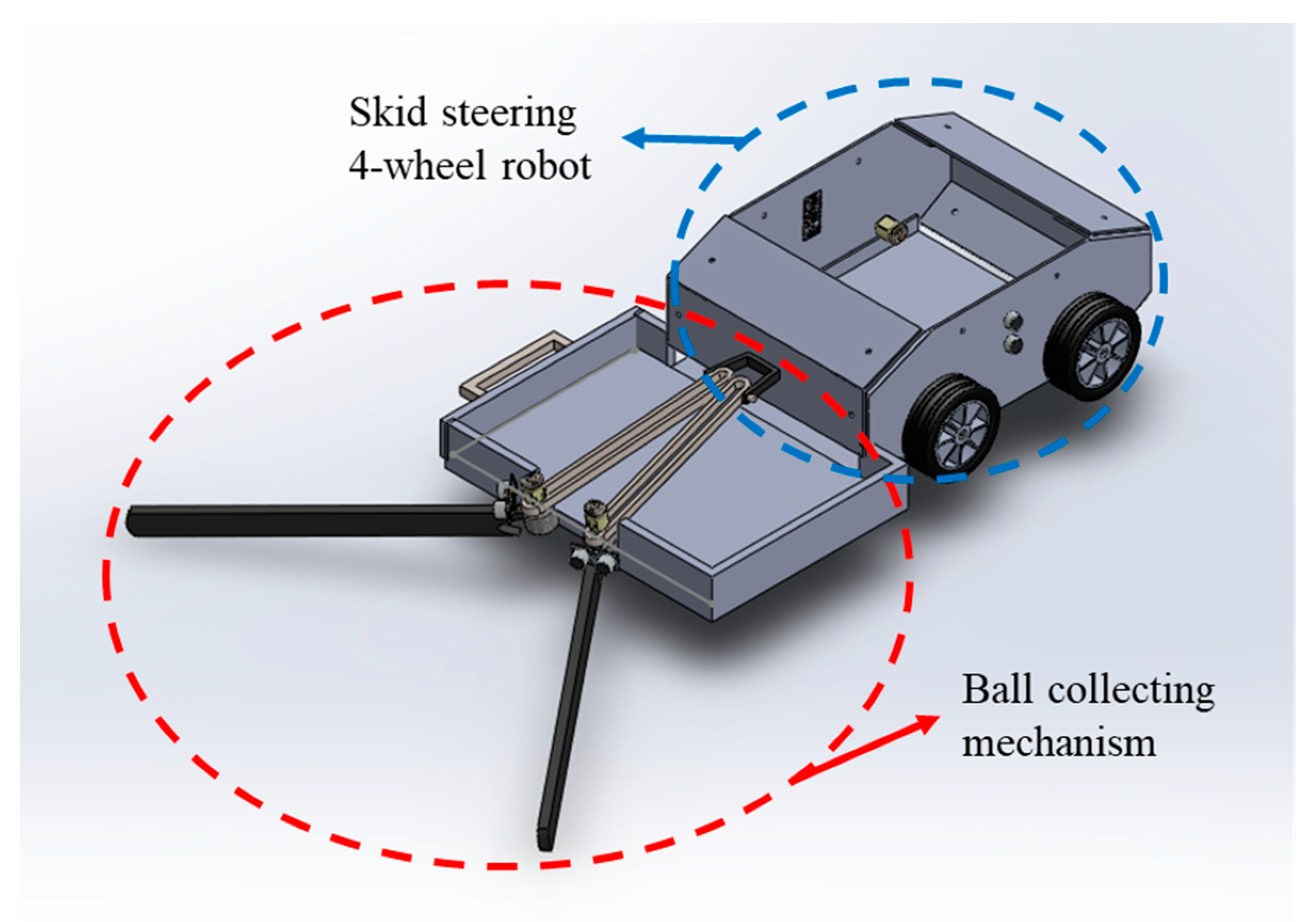
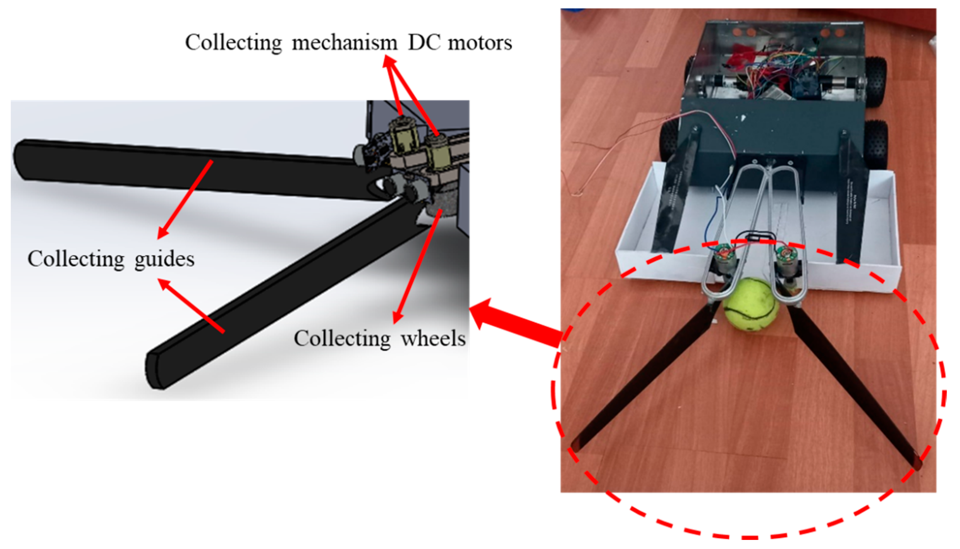
2.1. Structural Design

In this study, a tennis ball collecting robot was designed and produced that is composed of two main parts. The first part was a skid steering 4-wheel robot, and the second part was the ball collecting mechanism (Figure 1).
The main part was designed and produced with aluminum sheets that were 2 mm thick. Four brushed DC motors were used that were equipped with 4 encoders to get feedback from the wheel’s position and velocities. The skid steering concept was used for the robot. The collecting process was the process of picking up the balls from a tennis court. Various techniques can be used for ball collecting, including a vacuum suction mechanism or a robot manipulator with a gripper. In this study, the robot collection mechanism was based on a spinning drum that pushed tennis balls into a storing basket. Two brushed DC motors made the drums spin at the desired speed where one rotated clockwise and the other rotated counterclockwise with an aim to push the balls inside the storing basket (Figure 2).

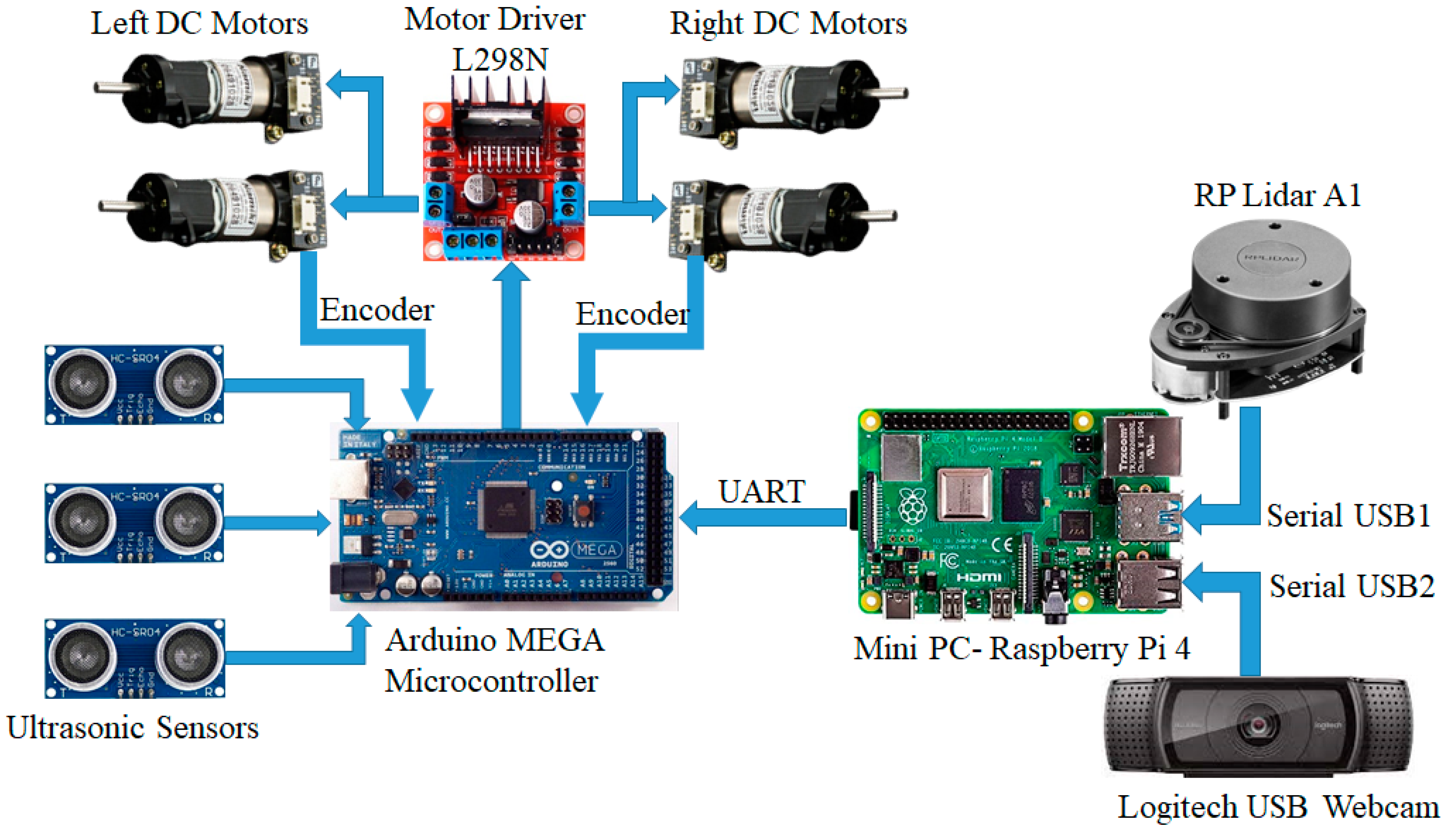
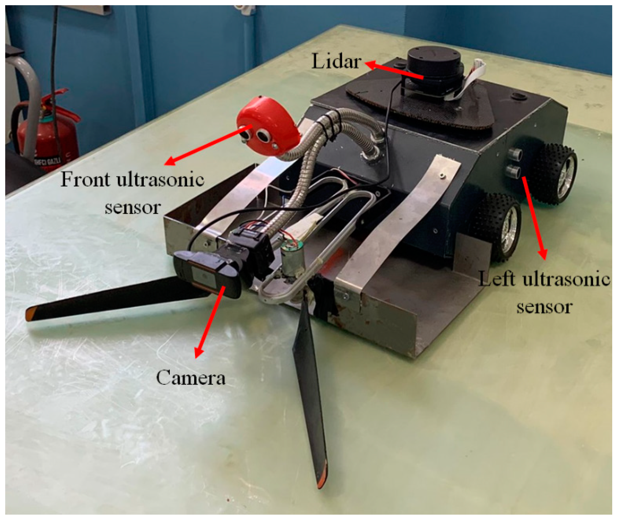
2.2. Robot Electronics

In this study, a mini-computer board and a microcontroller were used simultaneously for mapping, path planning, and controlling the robot’s motion. A Raspberry Pi4-B was chosen as a mini-computer board, and an Arduino Mega was used as the microcontroller. Herein, the Raspberry Pi was responsible for map generating, video processing, and path planning. The Arduino Mega microcontroller was used to control the 4 DC motors. It was also used to gather data from the ultrasonic sensors and supply collision prevention. The reason that a mini-computer and a microcontroller were used separately was to decrease the processing load of the Raspberry Pi minicomputer. Using the mini-computer GPIO pins for motor controlling and collision detection would make encountering delays in collision prevention of the robot probable and risky.
The schematic connection diagram between the robot components is shown in Figure 3.
The developed final prototype is shown in Figure 4. The only modification included the front ultrasonic sensor which was mounted on the top of the robot. Some conflicts happened during the ball collection operation, and these conflicts were solved by this modification.

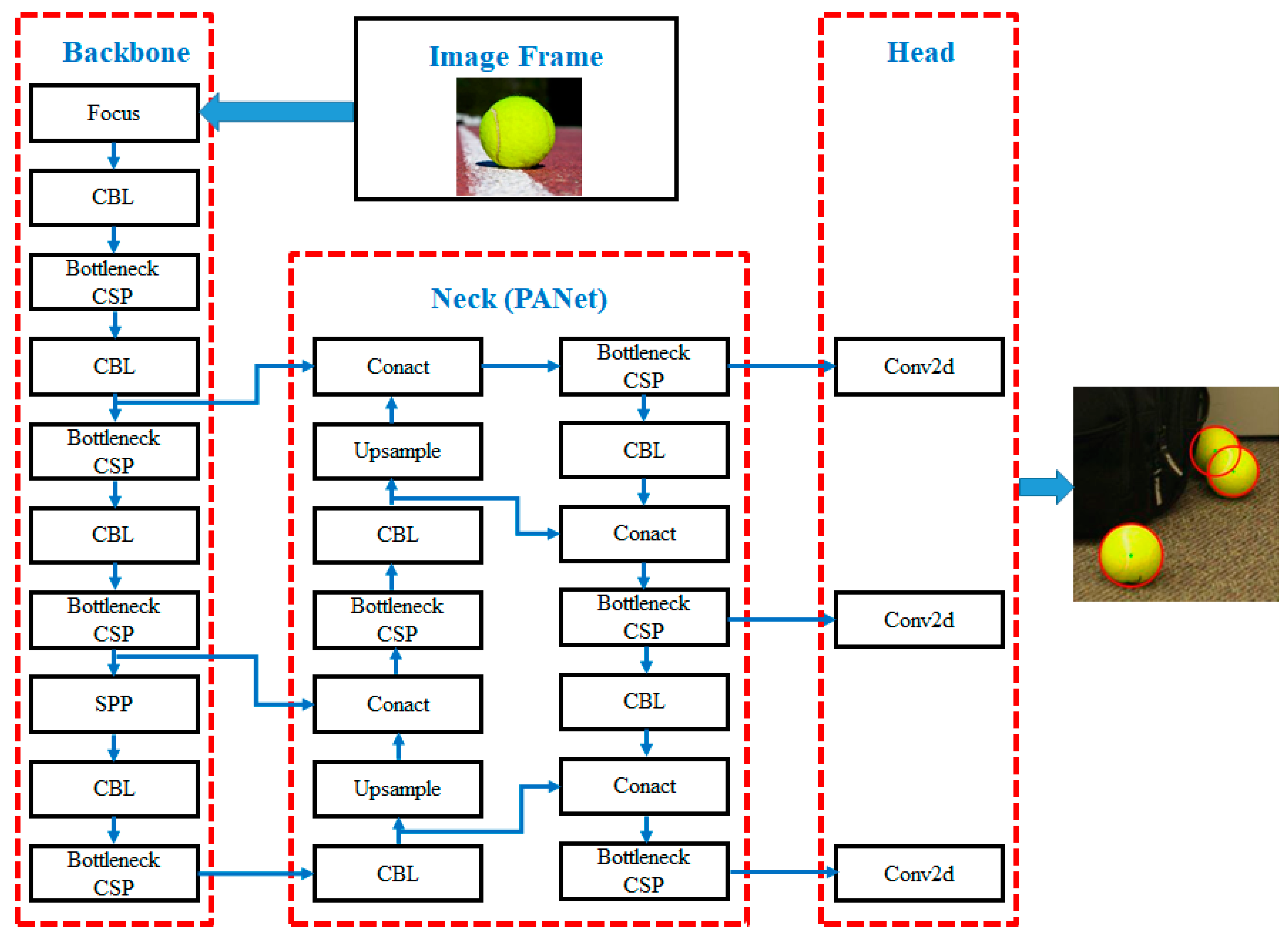
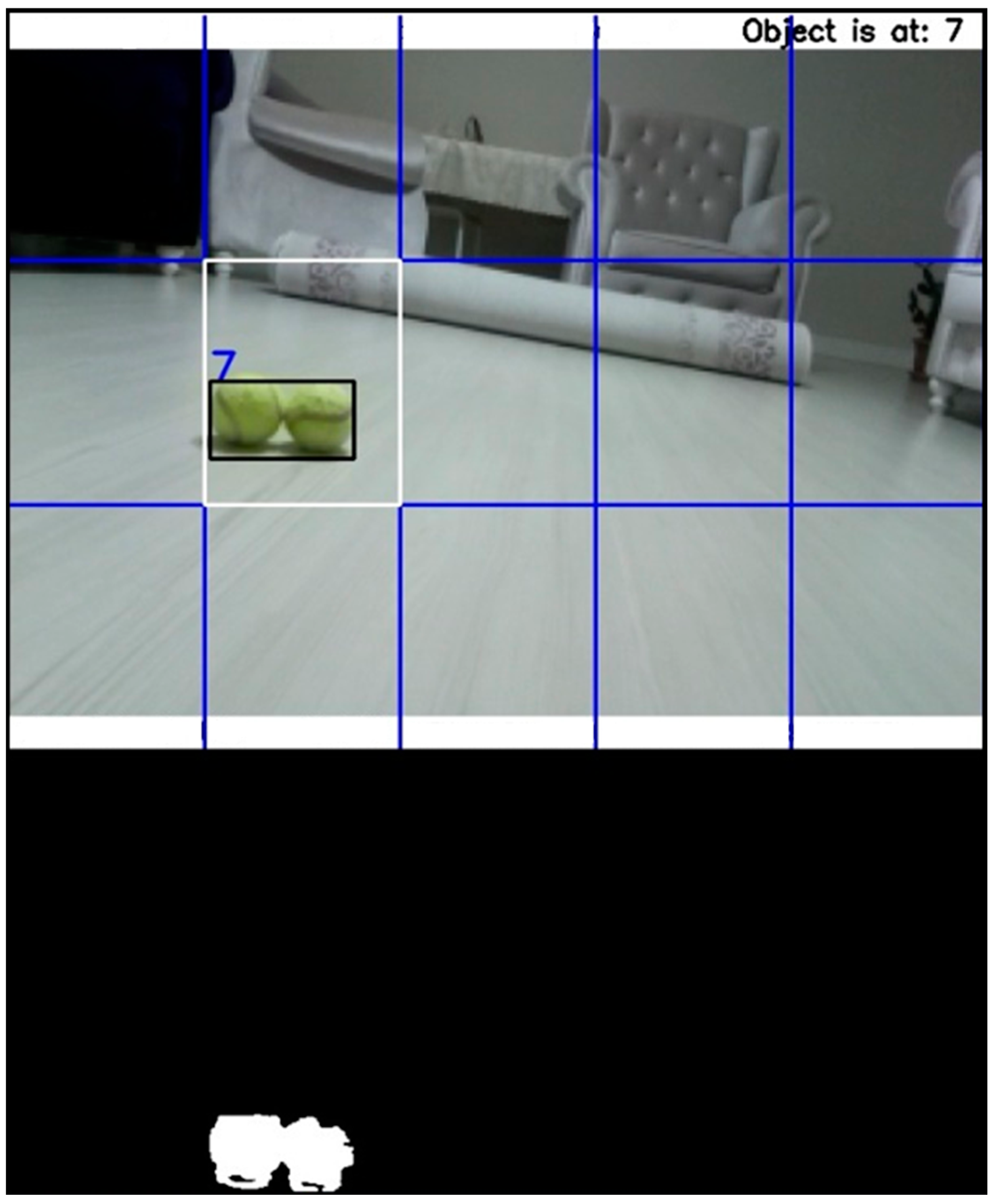
2.3. Tennis Ball Detection Using YOLOv5

One of the most important parts of a tennis ball collection robot is object (tennis ball) detection. In this study, the challenge was to use an algorithm that worked in different environments with various illuminations. Consequently, using RGB or HSV protocols and arranging the intensity range was not a trusted method for tennis ball detection. That is why a YOLOv5 algorithm was used in this study for tennis ball detection since it is a very powerful and accurate method.
In this section, we first discuss the network’s overall architecture. Then, we introduce the specifics of our updated classifier and the dataset’s evaluation criteria. This study employed a YOLOv5 object identification network and a multi-layer perceptron (MLP) neural network to classify tennis balls. Since May 2020, YOLO has made a significant breakthrough in its industry, which it has dominated for years. Two revised and improved versions of YOLO were released in quick succession. The first was Joseph Redmon and Alexey Bochkovskiy’s YOLOv4 [19], and the second was Glenn Jocher’s newly published YOLOv5. This new version was received with some criticism, but the v5 model has displayed a substantial increase in performance compared with its predecessors. YOLOv5 has a number of technical benefits. The most acclaimed change is the adoption of Python as the programming language instead of C, which was utilized in earlier versions. This considerably facilitates IoT device installation and integration. Furthermore, the PyTorch community is bigger than the Darknet community, suggesting that PyTorch gets more contributions and has a greater potential for future expansion.
The YOLOv5 network is made up of three main components:
a
The backbone, which consists of a CNN layer that combines image properties at multiple scales.
b
The neck, which is a layer collection that is used to gather visual attributes and pass them to prediction.
c
The head, which collects neck parameters and performs localization and classification.
As shown in Figure 5, all object detection designs share a property, which is that the input image characteristics are compressed by a feature extractor (backbone) and then transferred to the object detector (including the detection neck and detection head).
The detection neck (or neck) serves as a feature aggregator, combining and mixing the features created in the backbone to prepare for the next step in the detection head (or head). The head is in charge of detections as well as the classification and localization of each bounding box. The two-stage detector does these two jobs separately and then aggregates their findings (sparse detection), whereas the one-stage detector performs them simultaneously (dense detection). YOLO is a single-stage detector (You Only Look Once). Tennis ball images in various backgrounds and illuminations were utilized in this study to train the YOLO network.

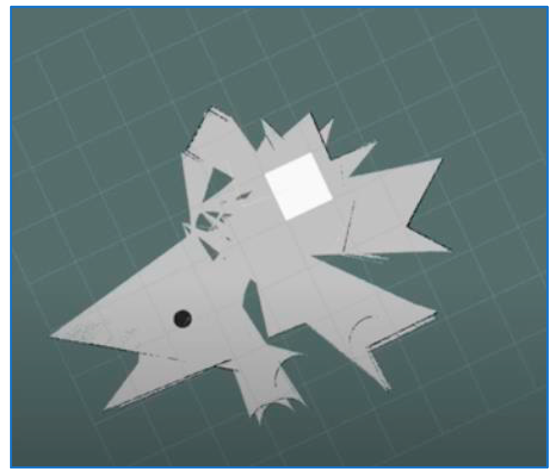
2.4. Environment Mapping Using the Hector Slam Method

In this study, LiDAR was used to map the working environment and designate a safe working area for the mobile robot. Based on data from the utilized LiDAR and SLAM (Simultaneous Localization and Mapping) techniques, a 2D map of the working environment was generated for each work setting. In robotics research, it is common for mobile robots to perform simultaneous localization and mapping (SLAM) in an unknown environment. SLAM is a technique for mapping an unknown area while monitoring the position of moving objects under specific conditions. We can perform SLAM using various sensors, including laser sensors with LiDAR or visual sensors with stereo cameras. A map of the environment is required for a mobile robot to move from room to room and collect and deposit objects. To perform these tasks, the robot must be aware of its surroundings as well as its position within them [20]. This study examined Hector SLAM, which was the LiDAR-based 2D-SLAM algorithm that was implemented in the robot operating system. Experiments were conducted to generate maps using the Hector SLAM method. The map was created in real-time, which allowed us to view the mobile robot’s path throughout its operation. The robot was equipped with an RP LiDAR A1 that was utilized for Hector SLAM. A robot operating system (ROS) was utilized to implement the SLAM algorithms. We could see the entire procedure due to the use of the RViz program. Additionally, the map was saved in the system. An ROS provides frameworks and tools for robot application and development. It includes components such as hardware abstraction, device drivers, libraries, visualizers, message forwarding, and package management. Mapping, localization, and autonomous navigation in an unfamiliar environment are all frequent challenges for autonomous mobile robots. An ROS serves as an operating system as well. The melodic release of an ROS was installed on a Linux workstation that was linked to LiDAR in the proposed project, and the data collected from LiDAR was used to generate a 2D map of the surrounding environment.
Hector SLAM is an open-source method that employs a laser scan sensor to generate a 2D grid map of the surrounding area. In contrast to existing SLAM algorithms that rely on wheel odometry, this algorithm determines the location of the robot through scan matching. Due to its rapid update rate, LIDAR can perform the scan matching function to detect borders and objects quickly and accurately. The initial frame data generated by LiDAR is immediately utilized to create a graph of the home location, after which the sensor data is compared with the map and the optimal position for the LiDAR unit is chosen [21]. The Hector algorithm employs the Gaussian–Newton minimization technique [22], which is regarded as an update to the Newton method and eliminates the need to calculate second derivatives. By obtaining the transformation specified by Equation (1) [23], this method was used to determine the optimal endpoint of the laser scan in relation to the map. The optimal location of the LiDAR unit was then transmitted to the ROS-operating hector mapping node. This served as the algorithm’s base link, and the odometry frame served as the base link and odometry frame for the algorithm by recording the ideal location of the LiDAR unit. Consequently, we were not required to provide odometry information. The optimal LiDAR position is represented as:
ζ = ( P x ,   P y , ψ ) T
The ζ is calculated by an argument of the minimum:
ζ * = a r g m i n i = 1 n [ 1 M ( S i ( ζ ) ) ] 2
where S i ( ζ ) represents the coordinates S i = [ S i x ,   S i y ] T of the endpoint coordinate of the LiDAR in the global coordinate system, as shown in Equation (3) below.
S i ( ζ ) = R z ( ψ ) · S i + [ P x ,   P y ] T
where the matrix R z ( ψ ) is the planar rotation around the Z-axis.
R z ( ψ ) = [ cos ( ψ ) sin ( ψ ) sin ( ψ ) cos ( ψ ) ]
where M ( S i ( ζ ) ) represents the 2-D grid map value when the coordinate is S i ( ζ ) .
Based on the Gauss–Newton gradient method [4], an initial estimation for ζ * ¯ is given according to Equation (5) to estimate Δ ζ * :
i = 1 n [ 1 M ( S i ( ζ * ¯ + Δ ζ * ) ) ] 2
The equation will be reduced by applying a Taylor expansion of the first order to Equation (5) and setting a partial derivative of Δ ζ * to 0:
Δ ζ * = H 1 i = 1 n [ M ( S i ( ζ * ¯ ) )   S i ( ζ * ¯ ) ζ * ¯ ] 2 [ 1 M ( S i ( ζ * ¯ ) ) ]
where
H = [ M ( S i ( ζ * ¯ ) )   S i ( ζ * ¯ ) ζ * ¯ ] T [ M ( S i ( ζ * ¯ ) )   S i ( ζ * ¯ ) ζ * ¯ ]

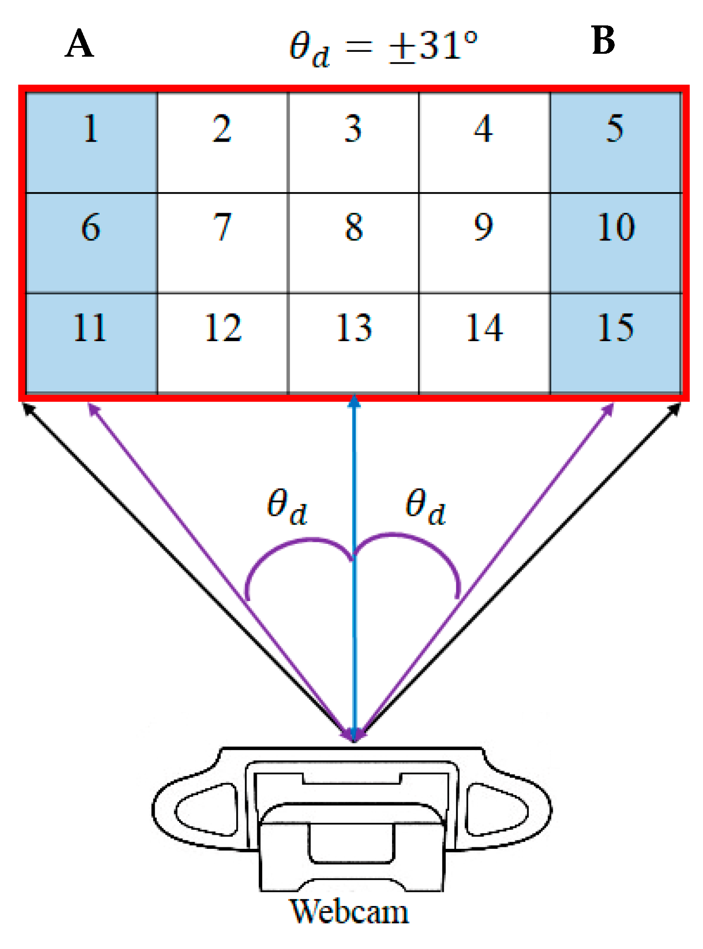
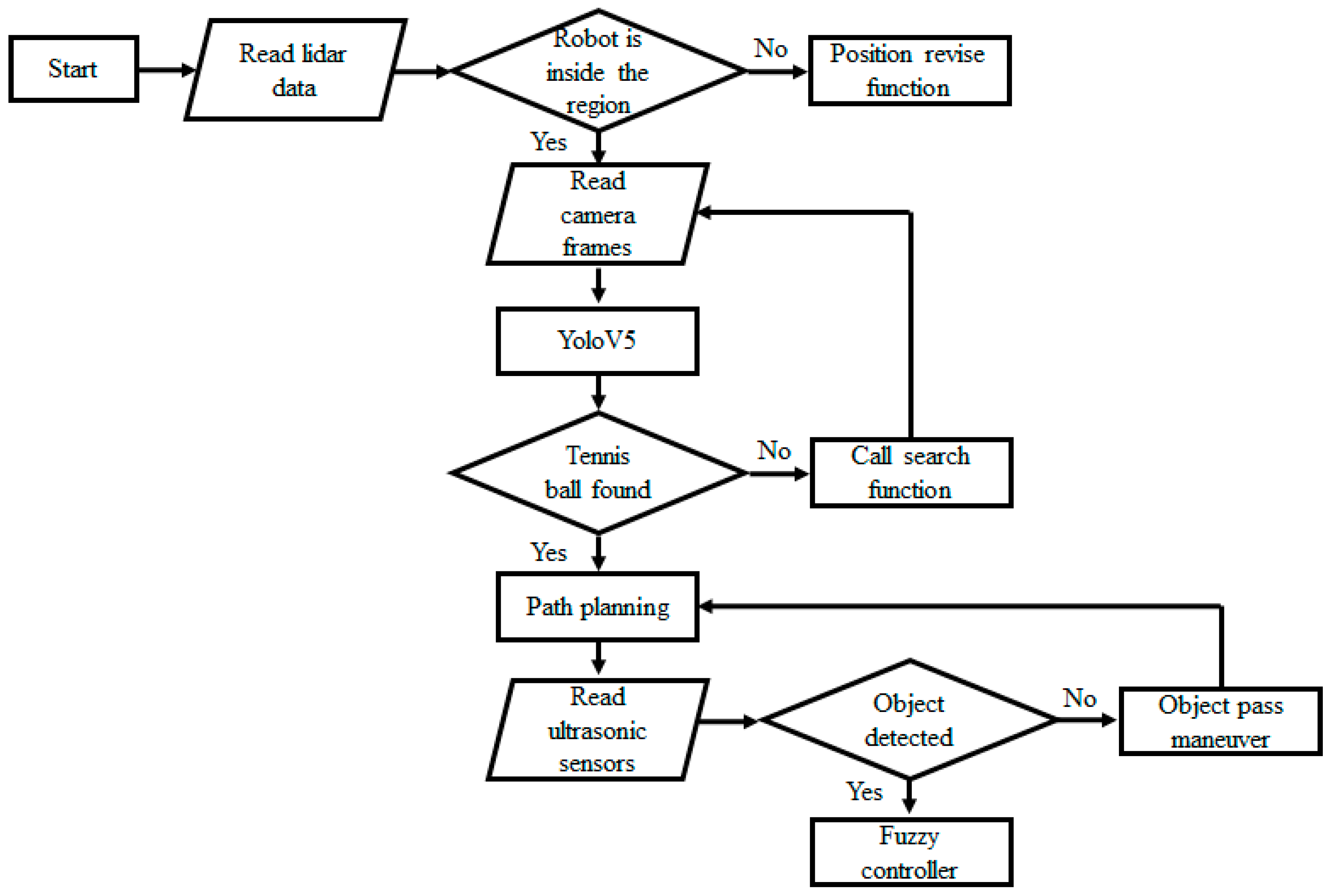
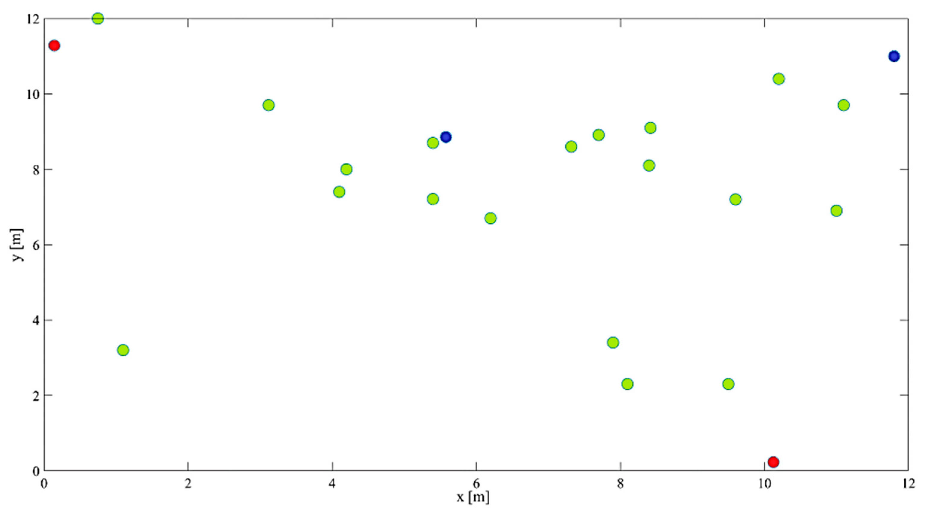
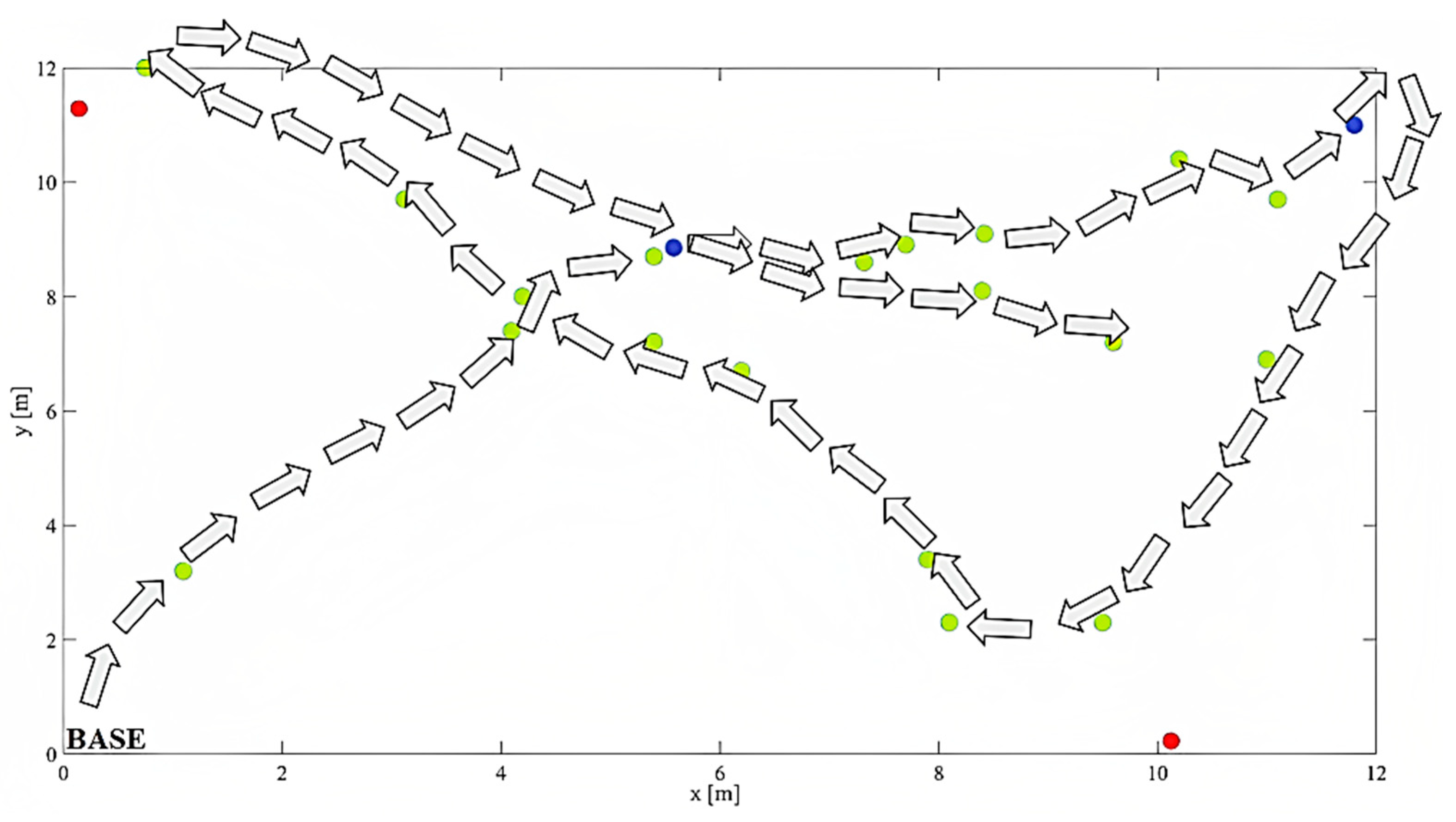
2.5. Navigation and Path Planning

In this section, the motion control principles of the developed UGV are explained. In this study, global path planning was restricted to the tennis court boundaries determined by LiDAR and Hector SLAM. The robot executes the local path planning algorithm in accordance with the identified boundaries. The design of a path-planning algorithm based on a single camera and local path-planning is one of the most important contributions of this study. It is a common technique to install a camera on top of a tennis court that is responsible for identifying the position of the robot and tennis balls in the global coordinate system. This method of path planning is not applicable to all courts and players because it is challenging and expensive to install cameras on the courts’ roofs. A cable-driven robot system is a common and expensive system that can be utilized for this purpose. Another challenge is to develop a wireless communication system between the camera and the robot for implementing the outcomes of the global path planning algorithm. This research tried to eliminate common global path planning by using a camera mounted on top of the tennis court. Using a single camera and the developed algorithm, the local coordinate system was utilized to control the robot. This strategy made the system flexible and able to be used standalone in every tennis court across the world without any necessary modifications or special equipment.
The study’s goals were as follows:
  • Searching for the working environment of the tennis balls.
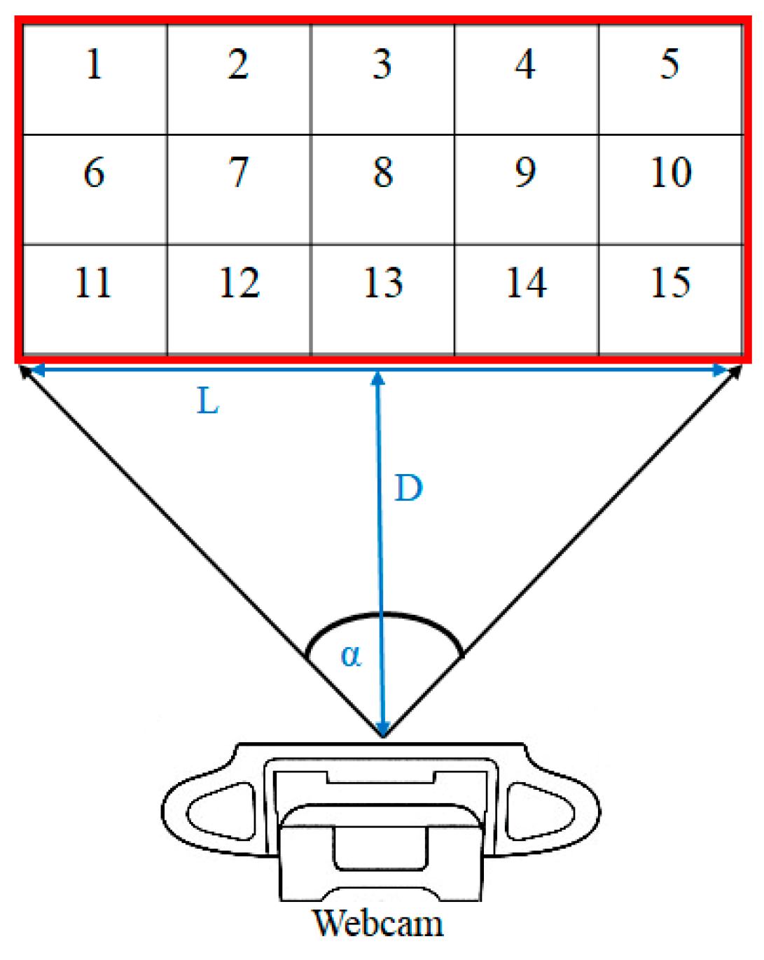
  • Path planning for the robot to the nearest balls using a single webcam.
  • Collision detection and obstacle avoidance.
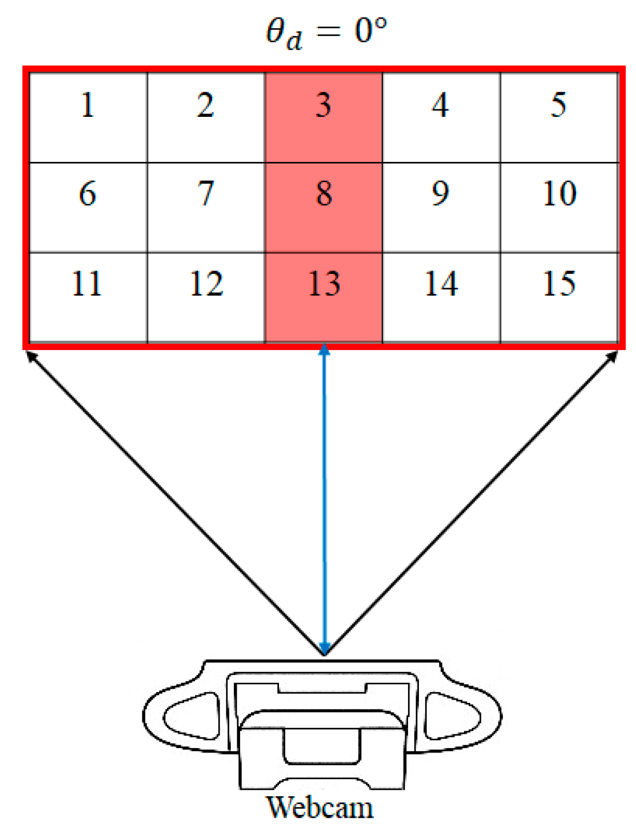
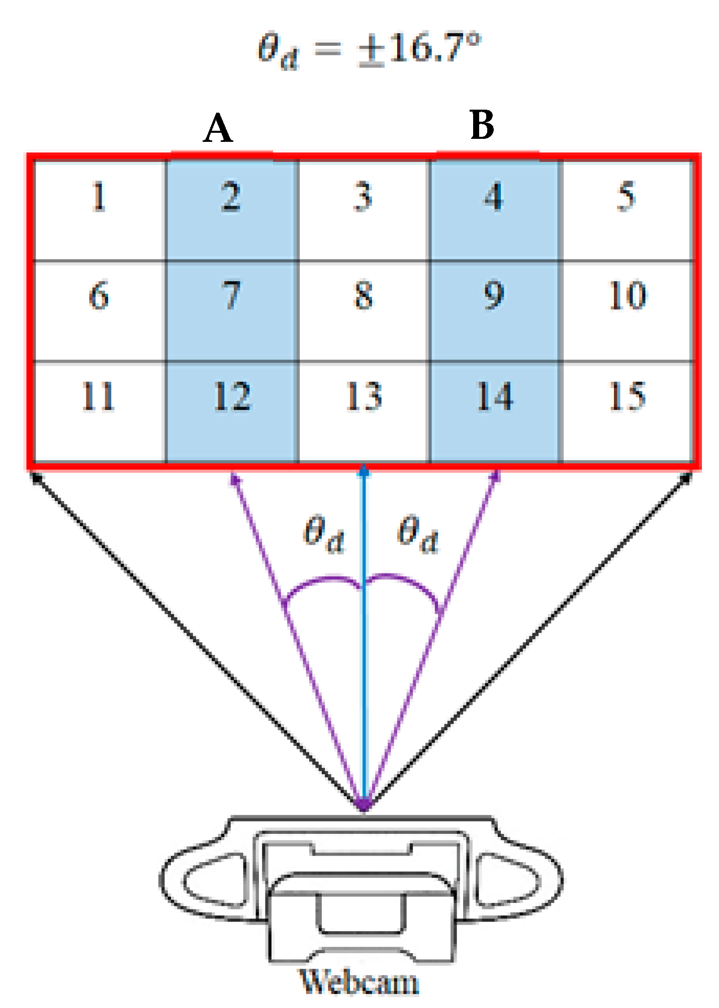
  • Calculating the desired heading angle for the navigation of the robot.
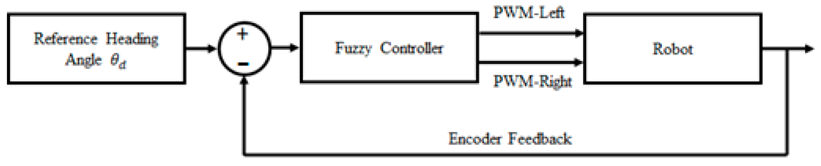
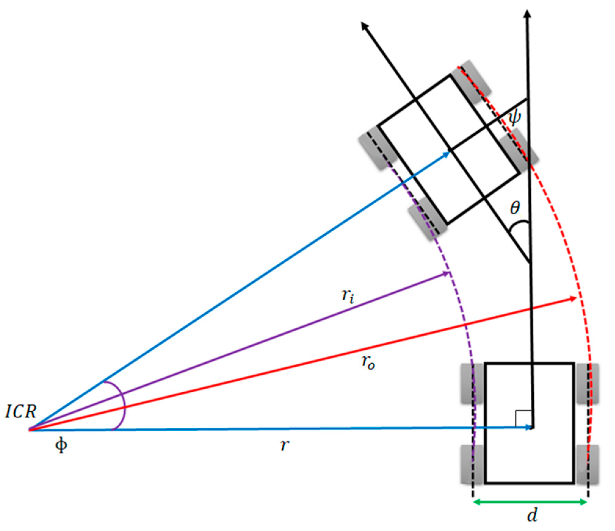
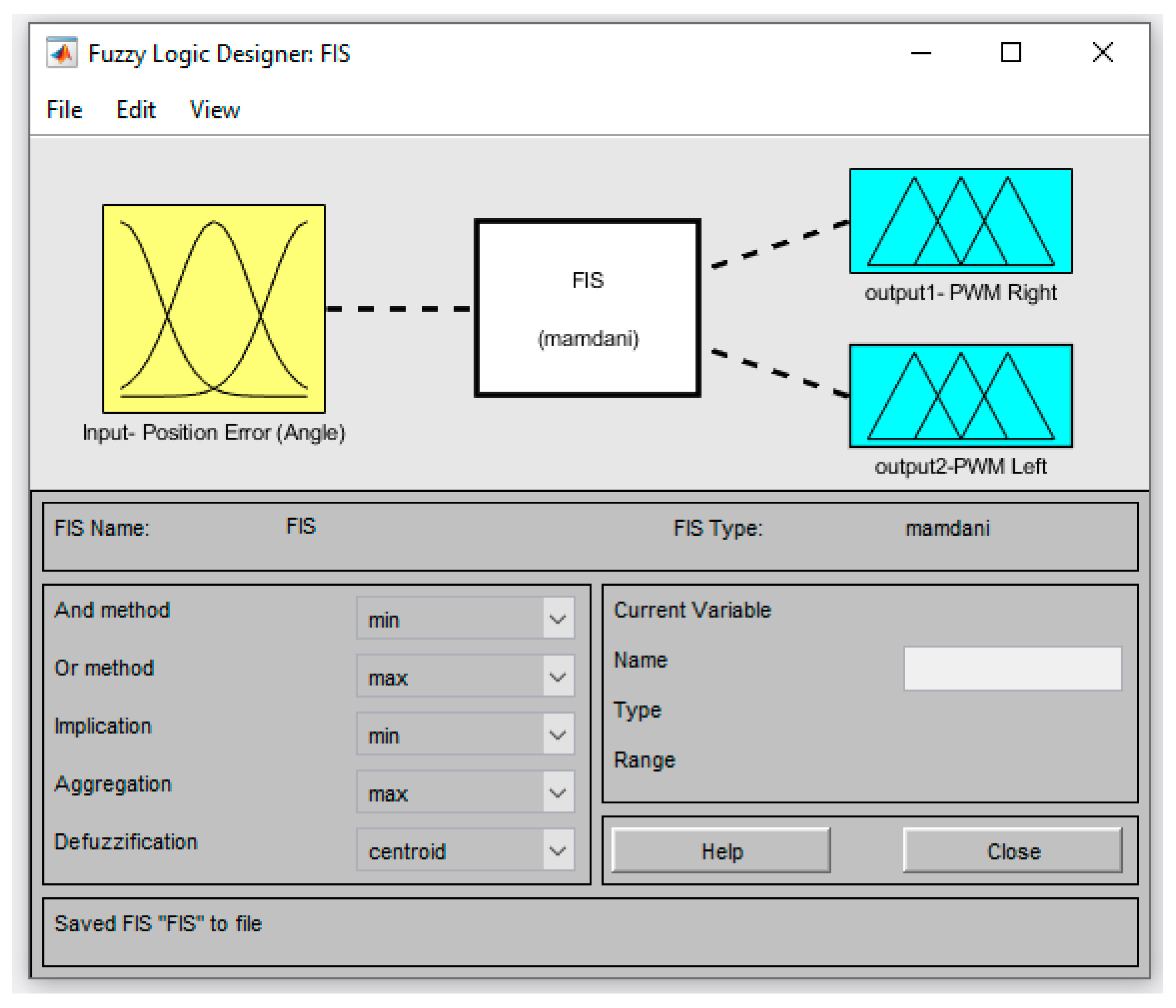
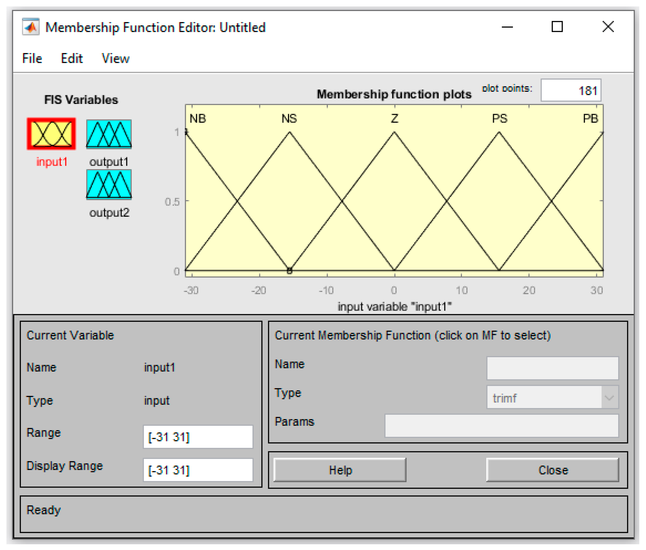
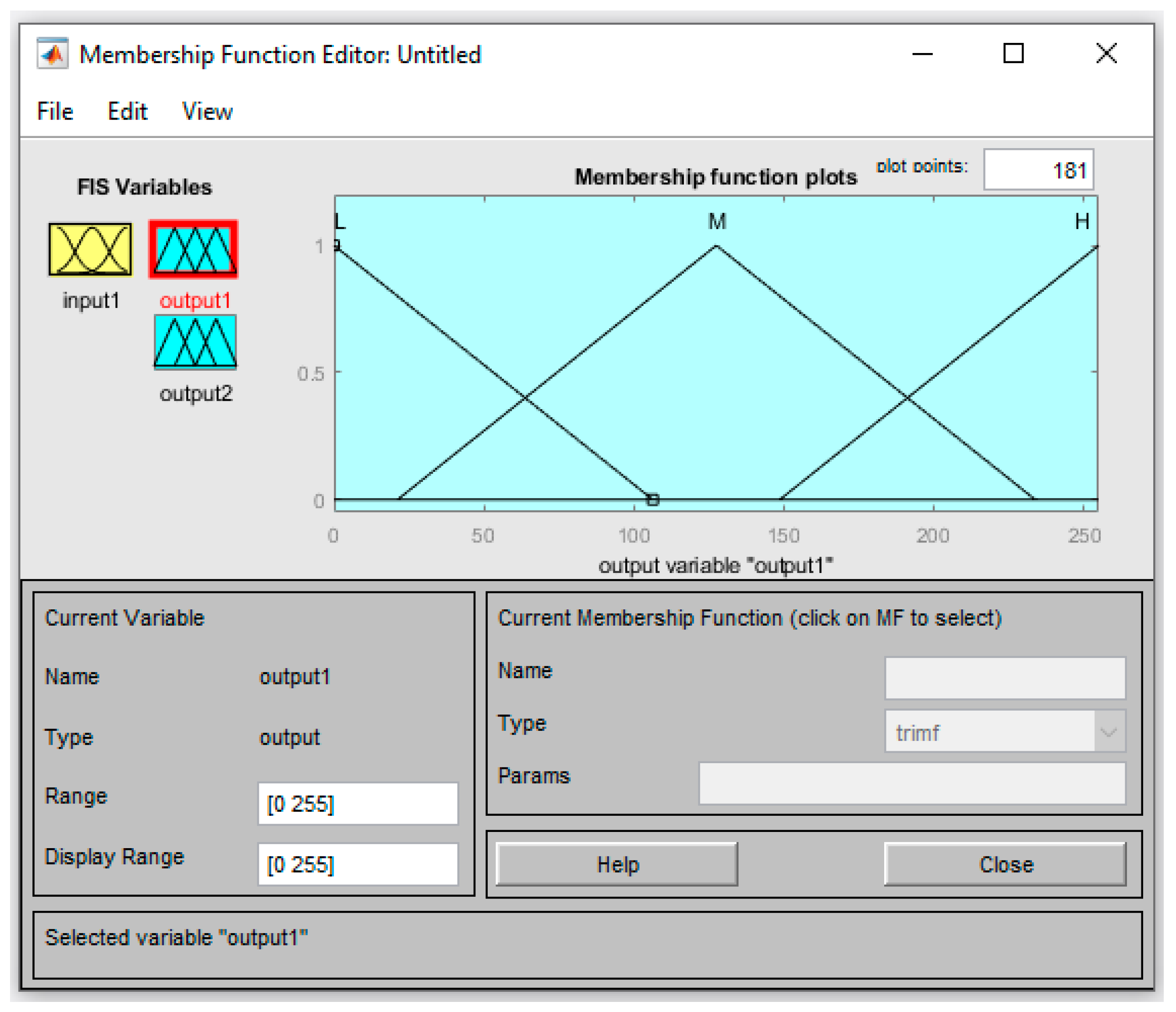
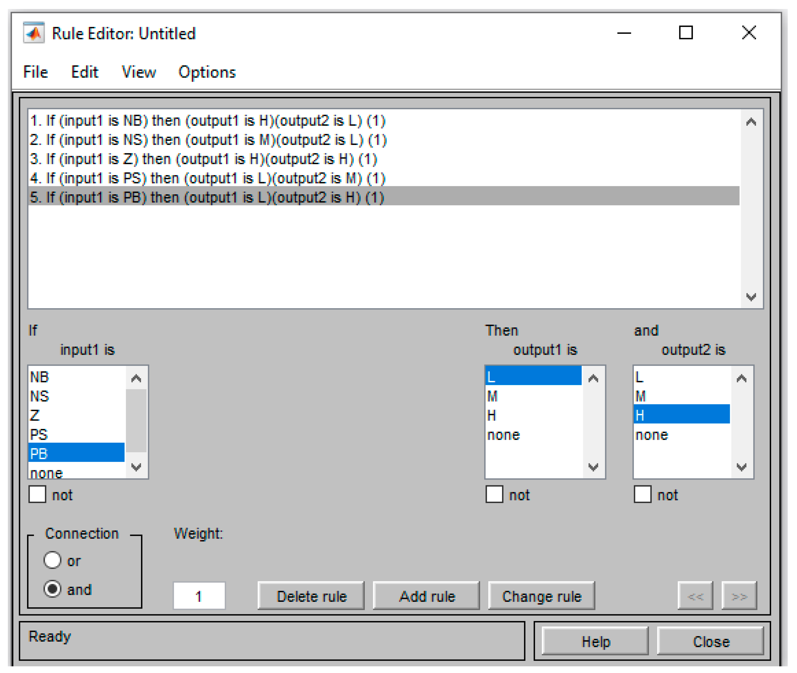
At the starting point, if the robot did not detect any tennis ball, the search function was called. While implementing the function, the robot began to rotate around itself in a clockwise direction where the right wheels rotated backward and the left wheels rotated forward. Using feedback from wheels’ encoders, the robot counted the number of balls and the related number of pixels every 10 degrees and recorded them in a matrix. A greater number of pixels identified the desired direction of motion. In this study, the main hypothesis in the path planning of the robot using a single camera, and in absence of the ball’s depth information, was “a higher number of pixels shows the nearest tennis ball and has a higher priority”. Based on this hypothesis, the camera frame was divided into 15 regions as shown in Figure 6.
During the ball collection mission, the robot moved toward the region that includes a higher number of tennis ball pixels, which is the direction of the nearest tennis ball. It is necessary to map a camera frame with the robot reference frame for this purpose. I.e., the desired heading angle should be identified for every 15 regions. There are three possible scenarios to control the heading angle of the robot. If the greater number of pixels related to the tennis balls belong to regions 3, 8 or 13, the robot should go forward to collect the closest ball set (Scenario 1—Figure 7). In this scenario the desired heading angle or reference input of the controller is θ d = 0 .
If the greater number of pixels related to the tennis balls belong to regions 2, 7 or 12, the robot should turn left slightly for θ d = 16.7 ° to collect the closest ball set (Scenario 2A—Figure 8). If the greater number of pixels related to the tennis balls belong to regions 4.9 or 14, the robot should turn right slightly for θ d = + 16.7 ° to collect the closest ball set (Scenario 2B—Figure 8).
If the greater number of pixels related to the tennis balls belong to regions 1, 6, or 11, the robot should turn left for θ d = 31 ° to collect the closest ball set (Scenario 3A—Figure 9). If the greater number of pixels related to the tennis balls belong to regions 5, 10, or 15, the robot should turn right for θ d = + 31 ° to collect the closest ball set (Scenario 3B—Figure 9).

2.6. Robot Control

The control algorithm of the robot is explained in this section. Generally, two control schemes can be considered for this robot. The global control strategy is responsible for keeping the robot inside the desired region and navigating the robot toward the closest tennis balls. Meanwhile, the local control strategy is responsible for the robot’s collision prevention and collision passing maneuvers. A flowchart of these robot control strategies is shown in Figure 10. After starting the operation, first, the robot position was checked manually or autonomously based on the LiDAR data and the 2D map generated by the Hector SLAM. If the robot’s position was not inside the desired region, then the position revise function was called, and the position revising maneuver was implemented. If the robot’s position was not inside the desired region, then the camera frame was captured and analyzed using the YOLO algorithm. At this stage, if the robot did not find a tennis ball, the search function was called as mentioned in the navigation and path planning section.
If the YOLO algorithm found the tennis balls, the number of pixels related to the detected balls in each of the 15 camera frame regions was calculated. Considering the pixel numbers, the path planning algorithm identified the desired heading angle of the robot, and this value was used as a reference input for the fuzzy controller. The fuzzy controller was responsible for navigating the robot toward the planned route by regulating its heading angle. However, during this navigation process, the priority was always the collision prevention algorithm. If the ultrasonic sensors sent feedback that detected an object in the robot’s way, the motion control of the robot was broken up, and a predefined object pass maneuver was implemented. Then, the path planning and fuzzy control stages were implemented again.

Fuzzy Controller Design

In this study, a fuzzy controller was developed and implemented to control the heading angle and speed of the motors. The general architecture of the controller is shown in Figure 10. First, the user specified a PWM value for the robot’s forward movement. This value was responsible for the speed of the robot when it moved in a forward direction, and the reference heading angle θ d was equal to zero. By running the controller, the reference heading angle θ d was identified using the algorithm explained in the Section 2.5. Afterward, the controller calculated the P W M values of the right and left wheels (see Figure 11).
The construction of a fuzzy inference system (FIS) refers to the act of constructing a map between a given input and an output using fuzzy logic. After the mapping has been established, decisions and patterns can be identified. The FIS applied in this paper was the Mamdani technique, which is a well-recognized method for capturing expert knowledge. This allowed us to describe the knowledge in ways that were more approachable and straightforward. However, fuzzy inference of the Mamdani kind is computationally intensive [24,25].
Based on the sign of the reference heading angle θ d , P W M signals were calculated by the fuzzy controller, and the updated PWM signals were sent to the left ( P W M L ) and right ( P W M R ) motors.
The difference between the speed of the left and right motors resulted in the rotation of the robot in the desired direction. The new heading angle was calculated considering the difference between the rotation angles of the left and right wheels (Figure 12).
Considering the Instantaneous Center of Rotation ( I C R ) , rotation radius ( r ) , inner rotation radius ( r i ) , and instantaneous rotation angle ( ) , and based on the encoders feedback, it was possible to obtain the inner and outer rotation arc lengths, L i   and   L o . Consequently, neglecting slippage of the wheels of the heading angle of the robot in the robot reference frame ( θ ) can be obtained as follows:
L i = r i   ɸ
L o = r o   ɸ
The difference between r o   and   r i is a constant value and equal to the distance between the left and right wheels ( d ) :
r o r i = d
Therefore, considering L i ,   L o ,   and   d as known parameters, from Equations (8)–(10), the instantaneous rotation angle ( ) can be calculated as follows:
ψ = π 2
θ = π 2 ψ =
As proved above, the heading angle of the robot in the robot reference frame θ is equal to the instantaneous rotation angle ( ) and can be calculated using feedback from the left and right wheels’ encoders.
In this article, the Fuzzy Logic Designer toolbox from Matlab software was adopted to design the required FIS. Figure 13 illustrates the designed FIS utilizing the MATLAB FIS toolbox. As seen in Figure 13, the input was the position error, and the two outputs were output 1 as the PWM of the right wheels and output 2 as the PWM of the left wheels.
Five membership functions were created for the input variable (position error), as shown in Figure 14: negative big (NB), negative small (NS), zero (Z), positive small (PS), and positive big (PB).
Three membership functions were created for the output variables (PWM right and PWM left), as shown in Figure 15 and Figure 16: Low (L), Medium (M), and High (H).
Based on the single input and two outputs of the controller, the rule base was constructed based on five rules (see Figure 17).

3. Results and Discussion

In this study, the developed tennis ball collection robot was tested in various conditions, and its performance was analyzed. As mentioned in the flowchart of Figure 9, after starting the mission, the robot began to create a 2D map of the working environment using Hector SLAM. An example of the generated map is shown in Figure 18.
The map generation algorithm was tested in various indoor environments. The Hector SLAM map generation algorithm has its advantages and disadvantages. An advantage is that it is independent of odometry data. Therefore, the map generation software can be run individually, and only its results are used to control the robot. However, due to a lack of odemetry feedback and fusion techniques, such as the Extended Kalman Filter, the generated 2D map may include some inaccuracies.
Tennis ball detection is an important part of the mission. The applied algorithm should be strong enough to handle various environment illuminations. It should also be applicable to minicomputers such as Raspberry Pi and able to process enough frames per second (FPS). In this study, the applied YOLOV5 method supplied 9 FPS. The supplied FPS is not a high value, but considering the low speed of the robot during ball collection operation, the supplied FPS was enough for this application. A comparison was done between the applied YOLO algorithm and the tennis ball detection using green pixels intensity ranges. For this purpose, the grabbed frames changed to the HSV (Hue Saturation Value) protocol, and based on the intensity values of the tennis balls in different environment illuminations, upper and lower limits were defined for the Hue, Saturation, and Value parameters. Both algorithms were tested to detect the 20 balls in three different indoor and outdoor environments. Even though the pixel intensity ranges provided higher FPS, the accuracy of the YOLO method was higher. The comparison results are mentioned in Table 1.
For the robot path planning and navigation using a single camera and a lack of depth information, the camera frame was divided into 15 regions, as explained in Section 2.5. An example of this implementation is shown in Figure 19. The binary image related to the selected pixels is also shown.
Figure 20 depicts the placement of 23 tennis balls in one-half of a tennis court to evaluate the performance of the developed algorithms. The origin of the figure was the base station where the tennis court net was placed. The robot started its motion from the base point. While implementing the explained path planning algorithm, the robot began to collect the tennis balls that were distributed on the court. The path followed by the robot is shown in Figure 21 and was based on the encoders’ data. As previously stated, if the robot failed to detect a tennis ball, the search function was activated. While implementing the function, the robot began to rotate in a clockwise direction until a tennis ball was detected or the mission ended. As depicted in Figure 20 and Figure 21 (91%) tennis balls were successfully detected by the robot’s YOLO algorithm. These balls are shown in green and blue colors. The green points successfully collected 19 tennis balls, which represents a success rate of approximately 83%. The blue points are the detected but not collected balls. There are two primary causes for the failure of this call collection. The first problem was structural as the robot collided with the balls and sent them in unintended directions as opposed to collecting them. This typically occurred when the balls were grouped closely together. Therefore, when the robot attempted to collect the closest ball, it would likely collide with neighboring balls and launch them in undesirable directions. The second reason was the absence of algorithms for the memorization of ball positions. This means that when the robot detected balls in multiple regions of the camera frame, it chose the closest one to collect. After collecting the closest ball or balls, the path planning algorithm continued to search for nearby tennis balls, possibly forgetting previously detected tennis balls that were too far away to be selected for collection in the previous step. As depicted in Figure 20, the YOLO algorithm missed two of the twenty-three balls (approximately nine percent). As shown in Figure 20 and Figure 21, these tennis balls were positioned along the tennis court’s perimeter, such as near the net. It is concluded that the path planning and fuzzy controller that were developed to control the robot and collect the tennis balls demonstrated a smooth and acceptable performance where more than 83% of the detected balls were collected.

4. Conclusions

In this study, an unmanned and autonomous robot was developed for tennis ball collection using LiDAR for 2D map generation of the working environment, a camera for ball detection and path planning, and three ultrasonic sensors for collision detection. The study’s findings show that the YOLO algorithm outperforms intensity-based segmentation approaches for detecting tennis balls. If such an intelligent algorithm is used for object detection and robot navigation, a simple webcam is enough for the robot’s control and its path planning, and there is no need for stereo cameras. Additionally, the study proves that a combination of a global control strategy that is responsible for general path planning and control schemes and a local control strategy that is responsible for collision prevention is very effective for autonomous vehicle control. Future studies should integrate a camera-based mapping module into the path planning algorithm. This module will be responsible for registering the detected ball numbers and their locations on a map and navigating the robot to collect the distributed balls without forgetting any. Future research should also incorporate various optimization cost functions, such as minimum power consumption or rapid collection of tennis balls at targeted regions, etc., into the path planning algorithm.

Author Contributions

All authors contributed to the conception and design of the study. M.L. carried out the robot design, manufacturing, modelling and SLAM algorithm development. A.A. accomplished Path Planning, Controller design, communication, and data analysis. Both authors drafted the initial edition of the article and provided feedback on prior versions of the manuscript. All authors have read and agreed to the published version of the manuscript.

Funding

The project received no funding.

Data Availability Statement

The related data are presented within the manuscript.

Conflicts of Interest

The authors declare they have no conflict of interest.

References

  1. Aamer, N.; Ramachandran, S. Neural networks based adaptive approach for path planning and obstacle avoidance for autonomous mobile robot (amr). Int. J. Res. Comput. Appl. Robot. (IJRCAR) 2015, 3, 66–79. [Google Scholar]
  2. Rashidnejhad, S.; Asfia, A.H.; Osgouie, K.G.; Meghdari, A.; Azizi, A. Optimal Trajectory Planning for Parallel Robots Considering Time-Jerk. Appl. Mech. Mater. 2013, 390, 471–477. [Google Scholar] [CrossRef]
  3. Azizi, A.; Entesari, F.; Osgouie, K.G.; Cheragh, M. Intelligent Mobile Robot Navigation in an Uncertain Dynamic Environment. Appl. Mech. Mater. 2013, 367, 388–392. [Google Scholar] [CrossRef]
  4. Azizi, A. Applications of Artificial Intelligence Techniques to Enhance Sustainability of Industry 4.0: Design of an Artificial Neural Network Model as Dynamic Behavior Optimizer of Robotic Arms. Complexity 2020, 2020, 8564140. [Google Scholar] [CrossRef]
  5. Latifinavid, M.; Azizi, A. Kinematic Modelling and Position Control of A 3-DOF Parallel Stabilizing Robot Manipulator. J. Intell. Robot. Syst. 2023, 107, 17. [Google Scholar] [CrossRef]
  6. Foo, S.W. Design and Develop of an Automated Tennis Ball Collector and Launcher Robot for both Able-Bodied and Wheelchair tennis Players-Ball Recognition Systems. Doctoral Dissertation, UTAR, Petaling Jaya, Malaysia, 2012. [Google Scholar]
  7. Liu, Y.; Li, S.; Xia, Z. Path Planning Efficiency Maximization for Ball-Picking Robot Using Machine Learning Algorithm. In Proceedings of the 2015 International Conference on Intelligent Transportation, Big Data and Smart City, Halong Bay, Vietnam, 19–20 December 2015; pp. 551–555. [Google Scholar]
  8. Wang, J. Ballbot a Low-Cost Robot for Tennis Ball Retrieval. Master’s Thesis, University of California, Berkeley, CA, USA, 2012. [Google Scholar]
  9. Gu, S.; Ding, L.; Yang, Y.; Chen, X. A new deep learning method based on alexnet model and ssd model for tennis ball recognition. In Proceedings of the 2017 IEEE 10th International Workshop on Computational Intelligence and Applications (IWCIA), Hiroshima, Japan, 11–12 November 2017; pp. 159–164. [Google Scholar]
  10. Gu, S.; Chen, X.; Zeng, W.; Wang, X. A deep learning tennis ball collection robot and the implementation on nvidia jetson tx1 board. In Proceedings of the 2018 IEEE/ASME International Conference on Advanced Intelligent Mechatronics (AIM), Auckland, New Zealand, 9–12 July 2018; pp. 170–175. [Google Scholar]
  11. Yun, C.H.; Moon, Y.S.; Ko, N.Y. Vision based navigation for golf ball collecting mobile robot. In Proceedings of the 13th International Conference on Control, Automation and Systems (ICCAS 2013), Gwangju, Republic of Korea, 20–23 October 2013; pp. 201–203. [Google Scholar]
  12. Wu, S.L.; Cheng, M.Y.; Hsu, W.C. Design and implementation of a prototype vision-guided golfball. In Proceedings of the IEEE International Conference on Mechatronics, Taipei, Taiwan, 10–12 July 2005. [Google Scholar]
  13. Perera, D.M.; Menaka, G.M.D.; Surasinghe, W.V.K.M.; Madusanka, D.K.; Lalitharathne, T.D. Development of a Vision Aided Automated Ball Retrieving Robot for Tennis Training Sessions. In Proceedings of the 2019 14th Conference on Industrial and Information Systems (ICIIS), Kandy, Sri Lanka, 18–20 December 2019. [Google Scholar]
  14. Nie, H.; Cai, G.; Liu, B.; Hu, X.; Yang, F.; Ni, J.; Hou, X. On Development of An Autonomous Ball Collecting Wheeled Mobile Robot. In Proceedings of the 2019 3rd Conference on Vehicle Control and Intelligence (CVCI), Hefei, China, 21–22 September 2019. [Google Scholar]
  15. dos Reis, D.H.; Welfer, D.; Cuadros, M.D.S.L.; Gamarra, D.T. Object Recognition Software Using RGBD Kinect Images and the YOLO Algorithm for Mobile Robot Navigation. In Proceedings of the International Conference on Intelligent Systems Design and Applications, Auburn, WA, USA, 3–5 December 2019; Springer: Cham, Switzerland, 2019. [Google Scholar]
  16. Afshar, S.; Derhami, V.; Jamshidi, F. Tennis ball trajectory estimation using GA-based fuzzy adaptive nonlinear observer. Int. J. Dyn. Control 2022, 10, 1685–1696. [Google Scholar] [CrossRef]
  17. Falsafi, M.; Alipour, K.; Tarvirdizadeh, B. Fuzzy motion control for wheeled mobile robots in real-time. J. Comput. Appl. Res. Mech. Eng. 2019, 8, 133–144. [Google Scholar]
  18. Faizah, F.; Triwiyatno, A.; Isnanto, R.R. Fuzzy Logic Implementation on Motion of Tennis Ball Picker Robot. In Proceedings of the 2021 IEEE International Conference on Communication, Networks and Satellite (COMNETSAT), Purwokerto, Indonesia, 17–18 July 2021. [Google Scholar]
  19. Redmon, J.; Farhadi, A. Yolov3: An incremental improvement. arXiv 2018, arXiv:1804.02767. [Google Scholar]
  20. Zaman, S.; Slany, W.; Steinbauer, G. ROS-based mapping, localization and autonomous navigation using a Pioneer 3-DX robot and their relevant issues. In Proceedings of the 2011 Saudi International Electronics, Communications and Photonics Conference (SIECPC), Riyadh, Saudi Arabia, 24–26 April 2011; IEEE: Piscataway, NJ, USA, 2011; pp. 1–5. [Google Scholar]
  21. Shen, D.; Xu, Y.; Huang, Y. Research on 2D-SLAM of indoor mobile robot based on laser radar. In Proceedings of the 2019 4th International Conference on Automation, Control and Robotics Engineering, Shenzhen, China, 19–21 July 2019; pp. 1–7. [Google Scholar]
  22. Yan, L.; Dai, J.C.; Tan, J.X. SLAM laser point cloud overall fine registration pose technology. J. Surv. Mapp. 2019, 48, 313–321. [Google Scholar]
  23. Kohlbrecher, S.; Von Stryk, O.; Meyer, J.; Klingauf, U. A flexible and scalable SLAM system with full 3D motion estimation. In Proceedings of the 2011 IEEE International Symposium on Safety, Security, and Rescue Robotics, Kyoto, Japan, 1–5 November 2011; pp. 155–160. [Google Scholar]
  24. Mishra, D.K.; Thomas, A.; Kuruvilla, J.; Kalyanasundaram, P.; Prasad, K.R.; Haldorai, A. Design of mobile robot navigation controller using neuro-fuzzy logic system. Comput. Electr. Eng. 2022, 101, 108044. [Google Scholar] [CrossRef]
  25. Lin, S.; Liu, A.; Wang, J.; Kong, X. A Review of Path-Planning Approaches for Multiple Mobile Robots. Machines 2022, 10, 773. [Google Scholar] [CrossRef]
Figure 1. UGV main parts.
Futureinternet 15 00084 g001
Figure 2. Ball collecting mechanism.
Futureinternet 15 00084 g002
Figure 3. Robot components connection diagram.
Futureinternet 15 00084 g003
Figure 4. Developed tennis ball collection robot.
Futureinternet 15 00084 g004
Figure 5. YOLOv5 network structure. CBL: Conv2D+BatchNormal+LeakyRELU; Bottleneck CSP: Cross Stage Partial; SPP: Spatial Pyramid Pooling.
Futureinternet 15 00084 g005
Figure 6. The camera frame was divided into 15 regions. α: camera field of view; L: camera horizontal field of view; D: Distance to object.
Futureinternet 15 00084 g006
Figure 7. Scenario 1: the closest set of tennis balls was accumulated in front of the robot.
Futureinternet 15 00084 g007
Figure 8. Scenario 2: the closest set of tennis balls was accumulated slightly left (A) or slightly right (B) of the robot heading.
Futureinternet 15 00084 g008
Figure 9. Scenario 3: the closest set of tennis balls was accumulated left (A) or right (B) of the robot heading.
Futureinternet 15 00084 g009
Figure 10. A flowchart of the robot control strategies.
Futureinternet 15 00084 g010
Figure 11. General architecture of the controller.
Futureinternet 15 00084 g011
Figure 12. Heading angle calculation.
Futureinternet 15 00084 g012
Figure 13. The designed FIS controller.
Futureinternet 15 00084 g013
Figure 14. Input membership functions.
Futureinternet 15 00084 g014
Figure 15. Output1—PWM right membership functions.
Futureinternet 15 00084 g015
Figure 16. Output2—PWM left membership functions.
Futureinternet 15 00084 g016
Figure 17. Fuzzy rule base.
Futureinternet 15 00084 g017
Figure 18. 2D map generation using Hector SLAM.
Futureinternet 15 00084 g018
Figure 19. Path planning using a single camera with 15 regions of the camera scene.
Futureinternet 15 00084 g019
Figure 20. Distribution of the tennis balls on half of the tennis court. Green points are detected and successfully collected balls. Blue points are detected but not collected balls. Red points are the unsuccessfully detected tennis balls.
Futureinternet 15 00084 g020
Figure 21. The path is followed by the robot during ball collection. Green points are detected and successfully collected balls. Blue points are detected but not collected balls. Red points are the unsuccessfully detected tennis balls.
Futureinternet 15 00084 g021
Table 1. Comparison between tennis ball detection YOLOV5 and HSV pixel intensity limits.
MethodSupplied FPSDetection Accuracy
YOLOv5991%
HSV intensity limits2171%
Disclaimer/Publisher’s Note: The statements, opinions and data contained in all publications are solely those of the individual author(s) and contributor(s) and not of MDPI and/or the editor(s). MDPI and/or the editor(s) disclaim responsibility for any injury to people or property resulting from any ideas, methods, instructions or products referred to in the content.

