
Flying Watchdog-Based Guard Patrol with Check Point Data Verification


Abstract
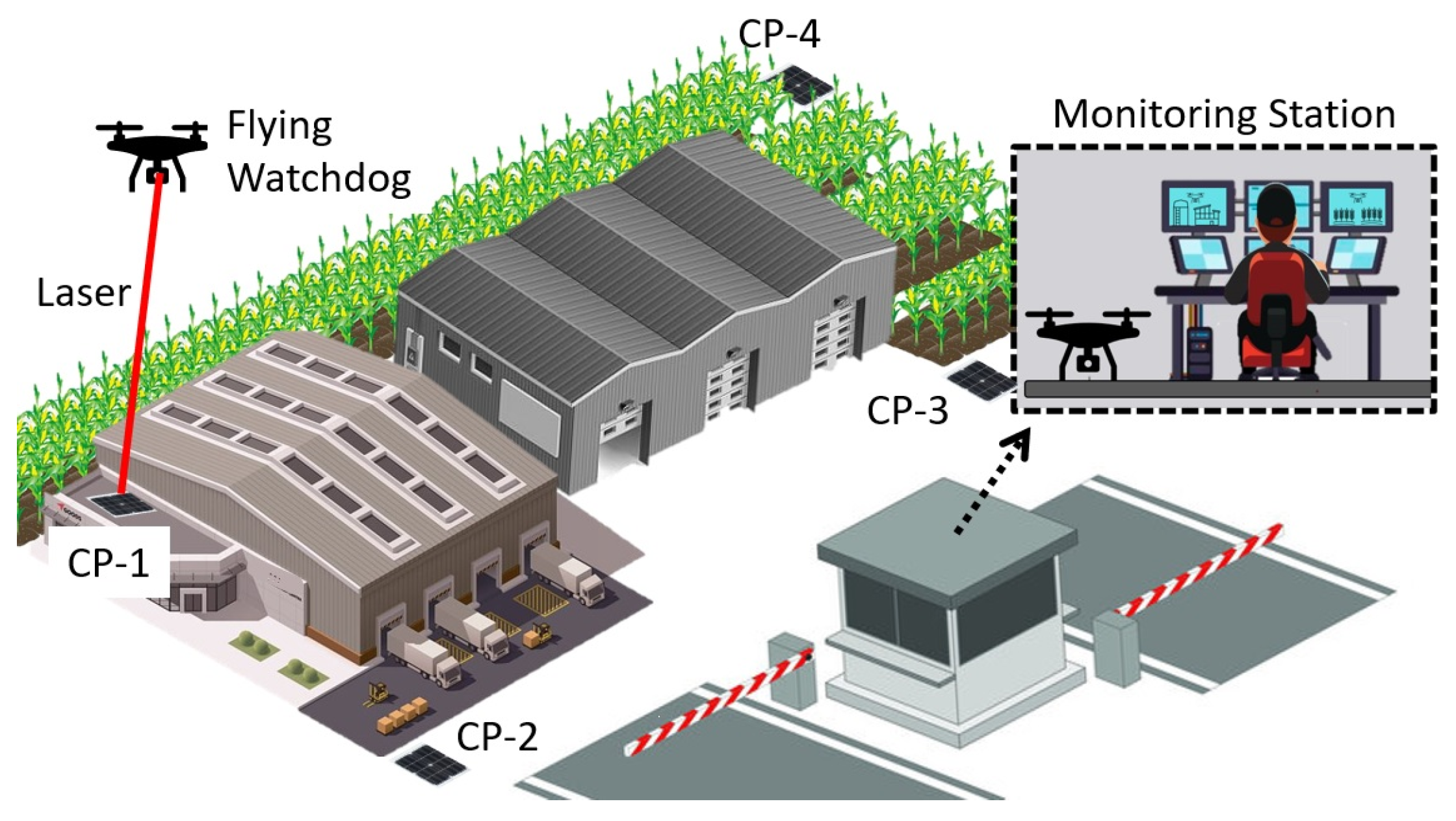
:1. Introduction
- Light pattern detection with vision-based technology;
- Laser data communication through the air;
- Drone check-in pad with remote monitoring capability.
2. Related Work
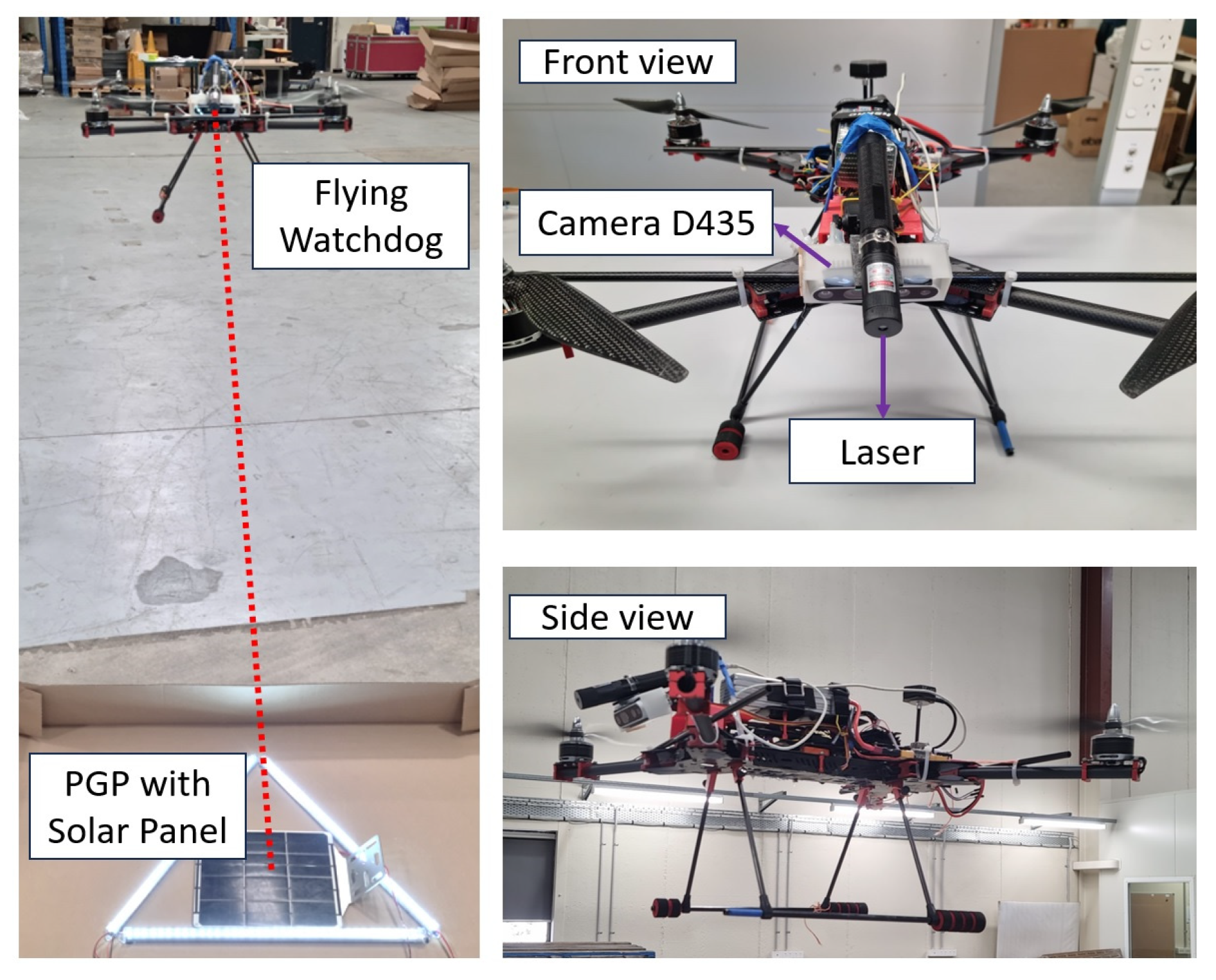
3. Proposed Flying Watchdog Architecture
3.1. Flying Watchdog Model
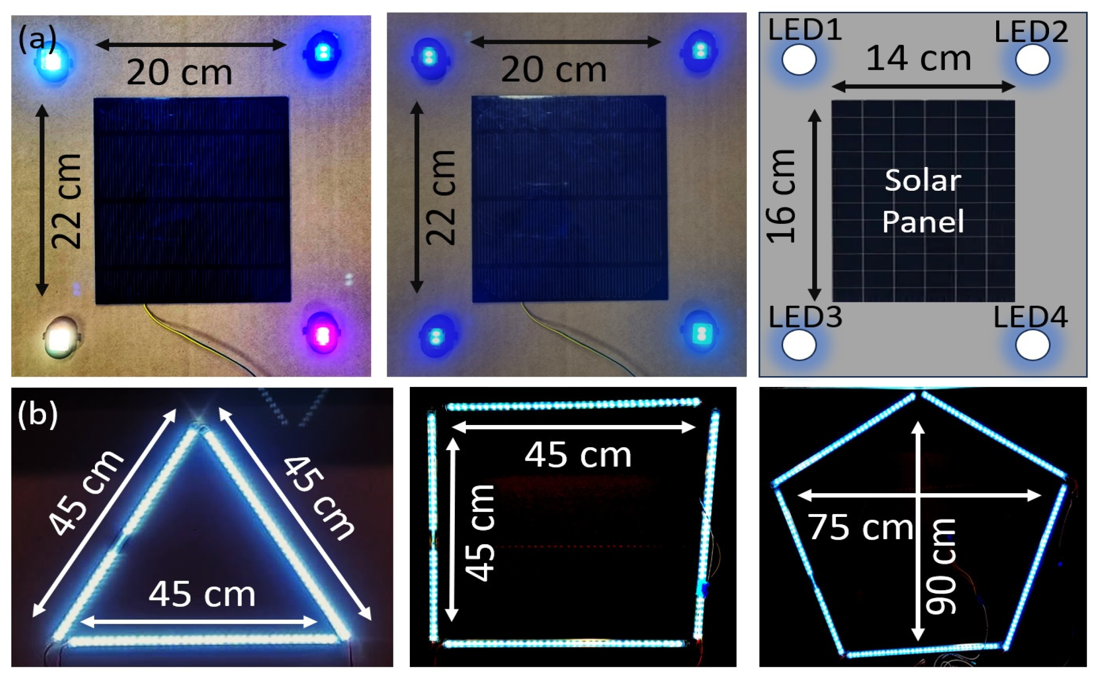
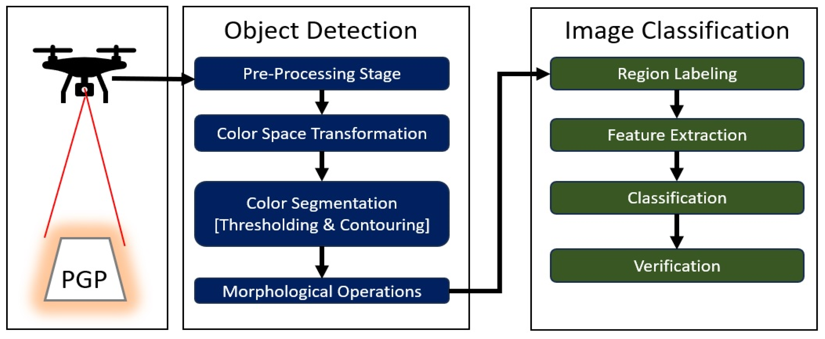
3.2. PGP Detection Model
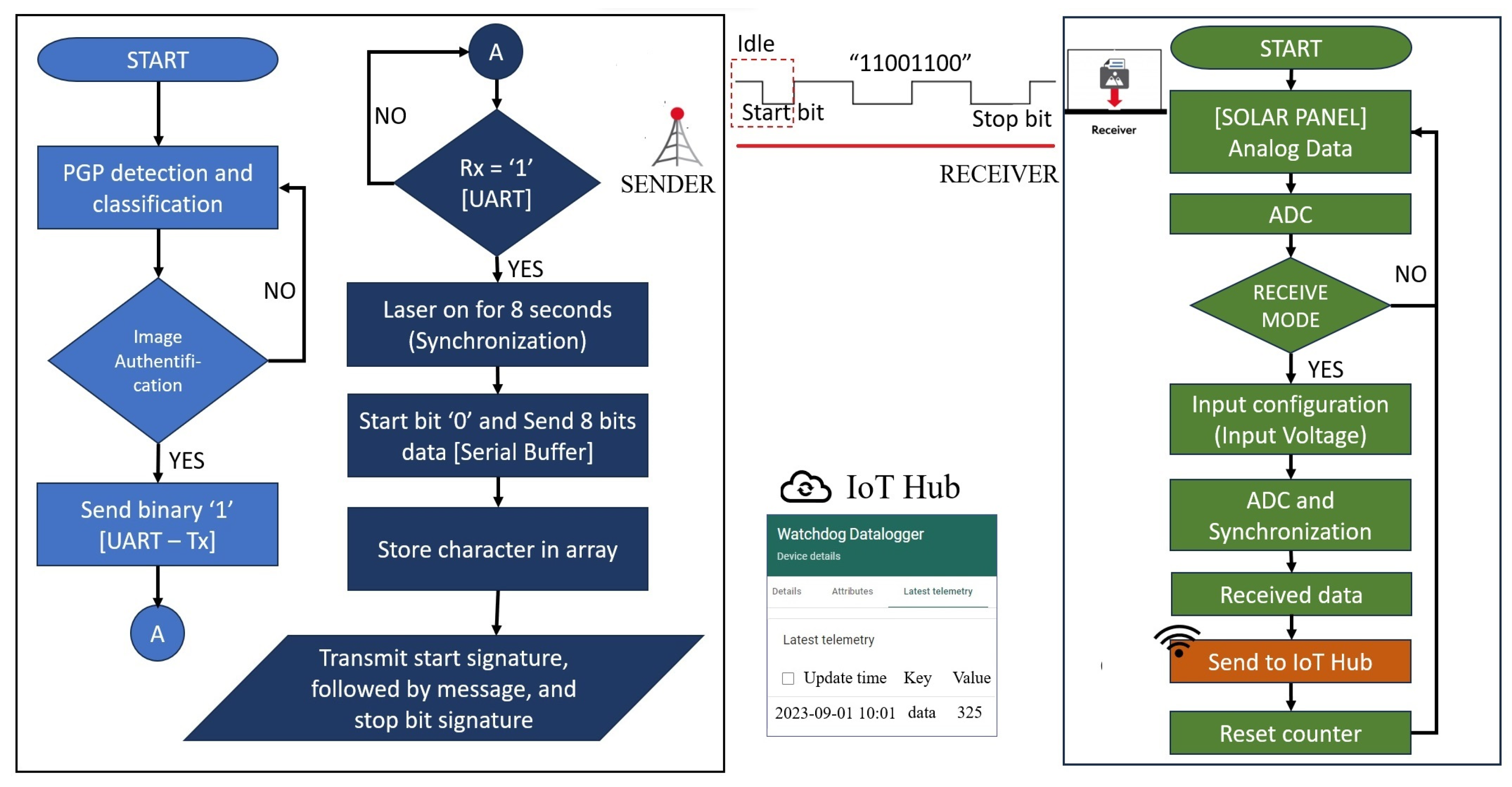
3.3. Data Communication via Air
4. Results and Discussion
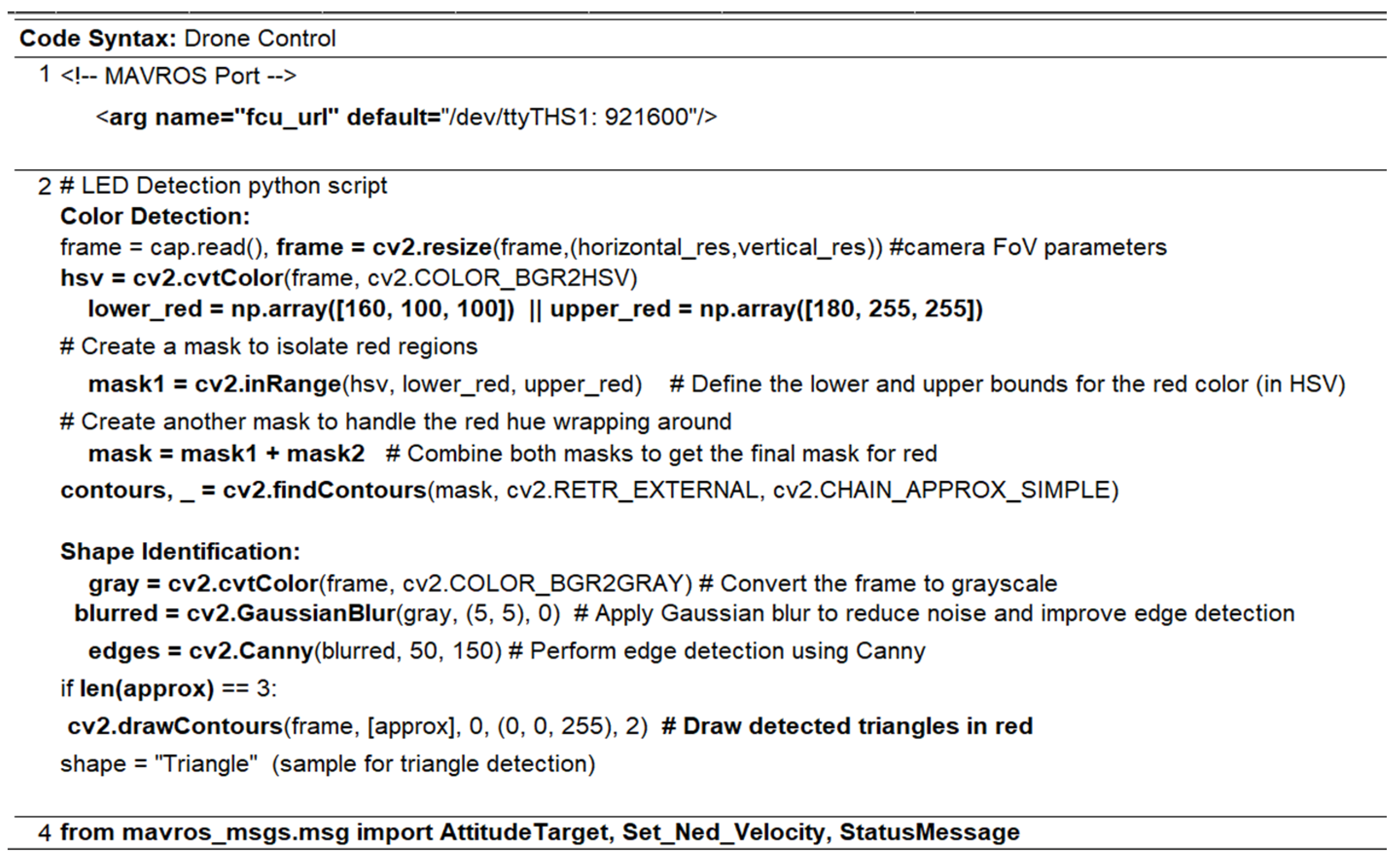
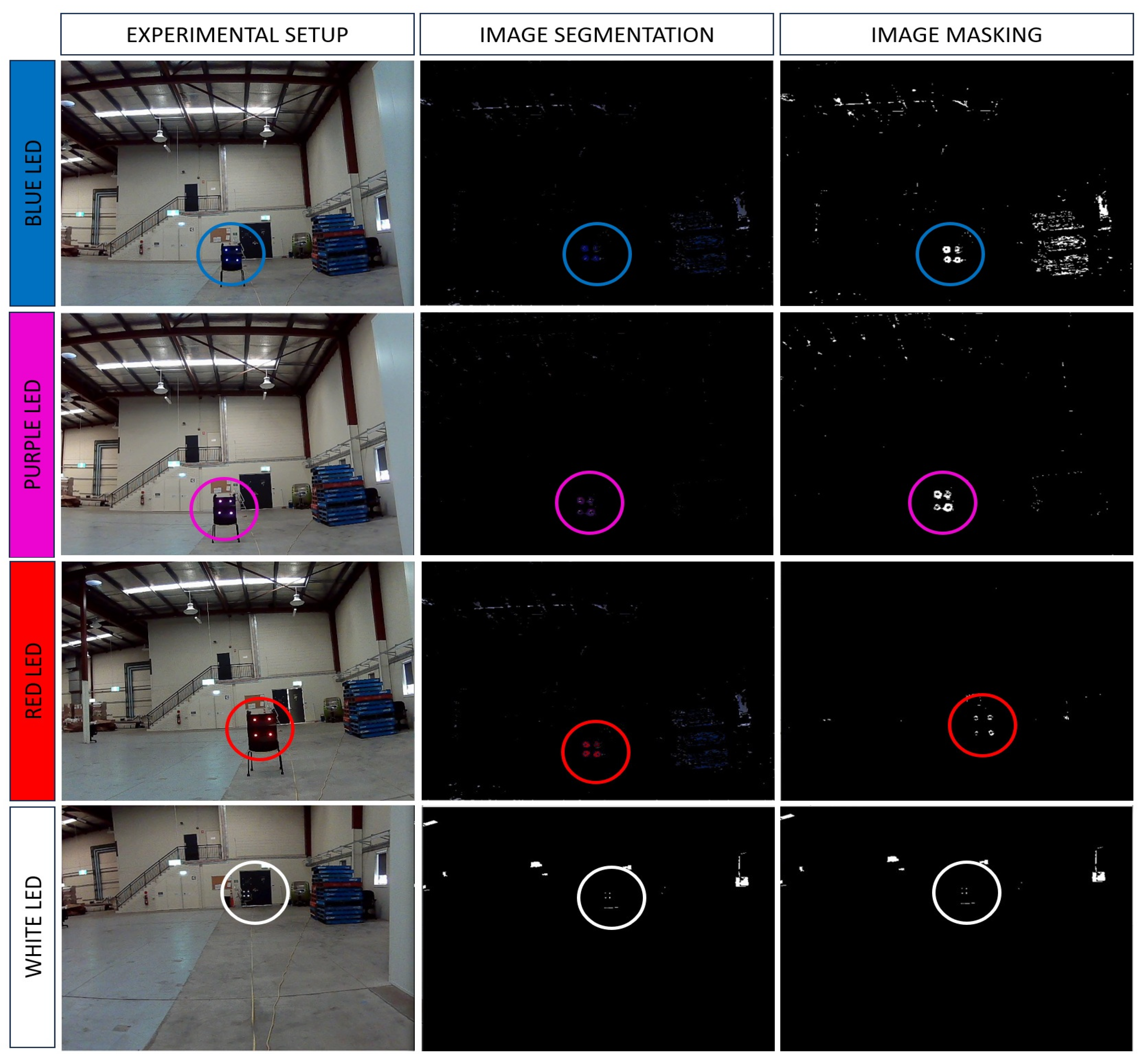
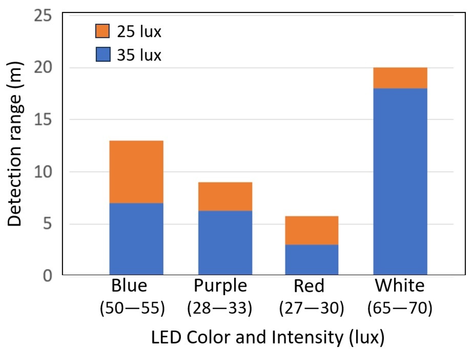
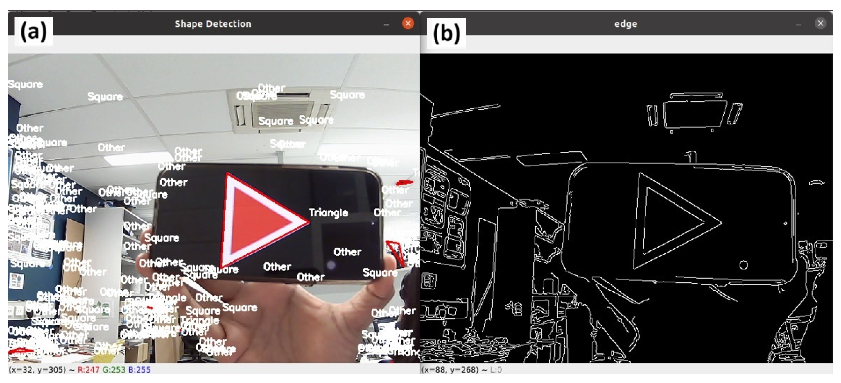
4.1. Light Color and Pattern Detection Based on OpenCV
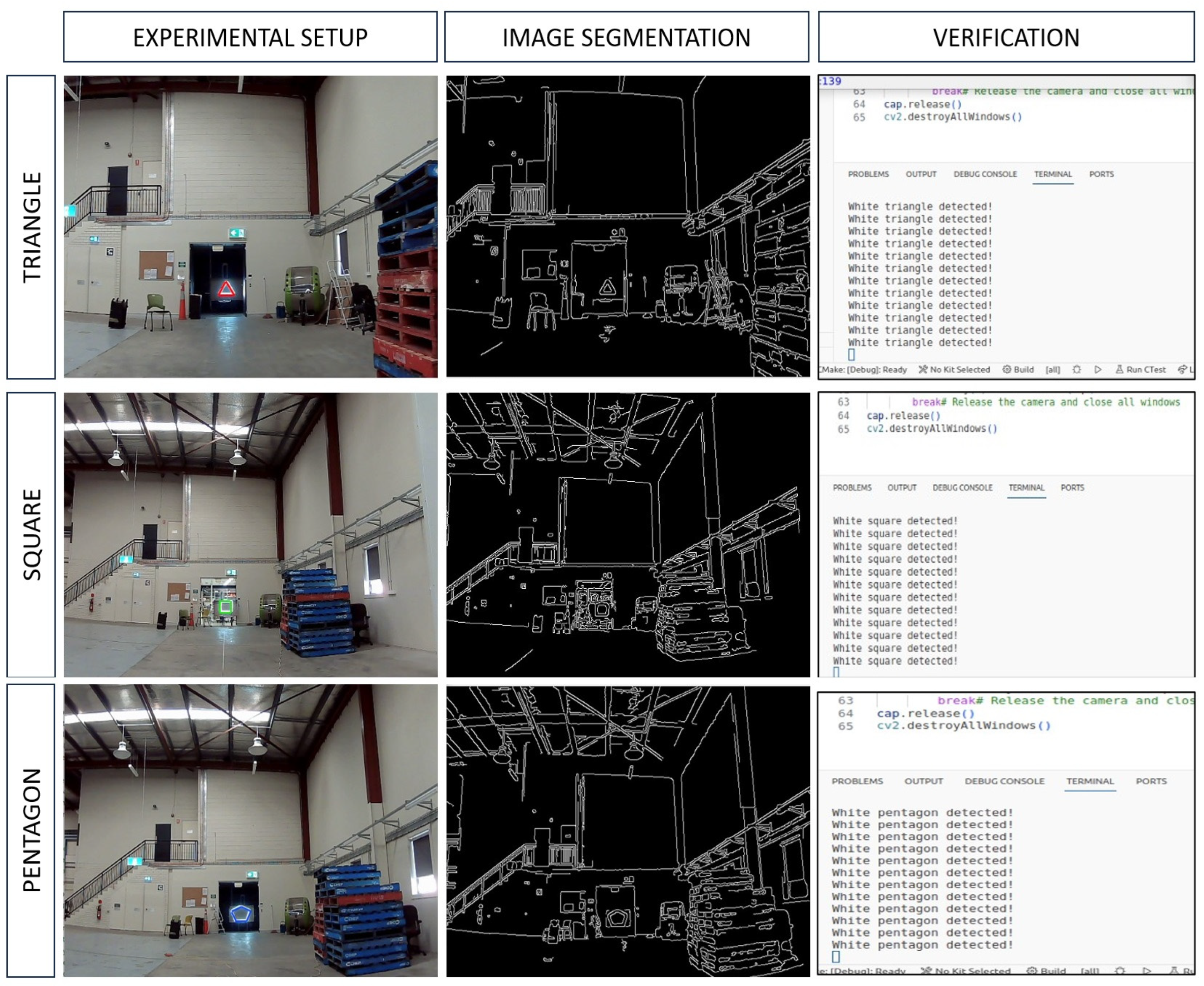
4.2. Light Shape Pattern Detection
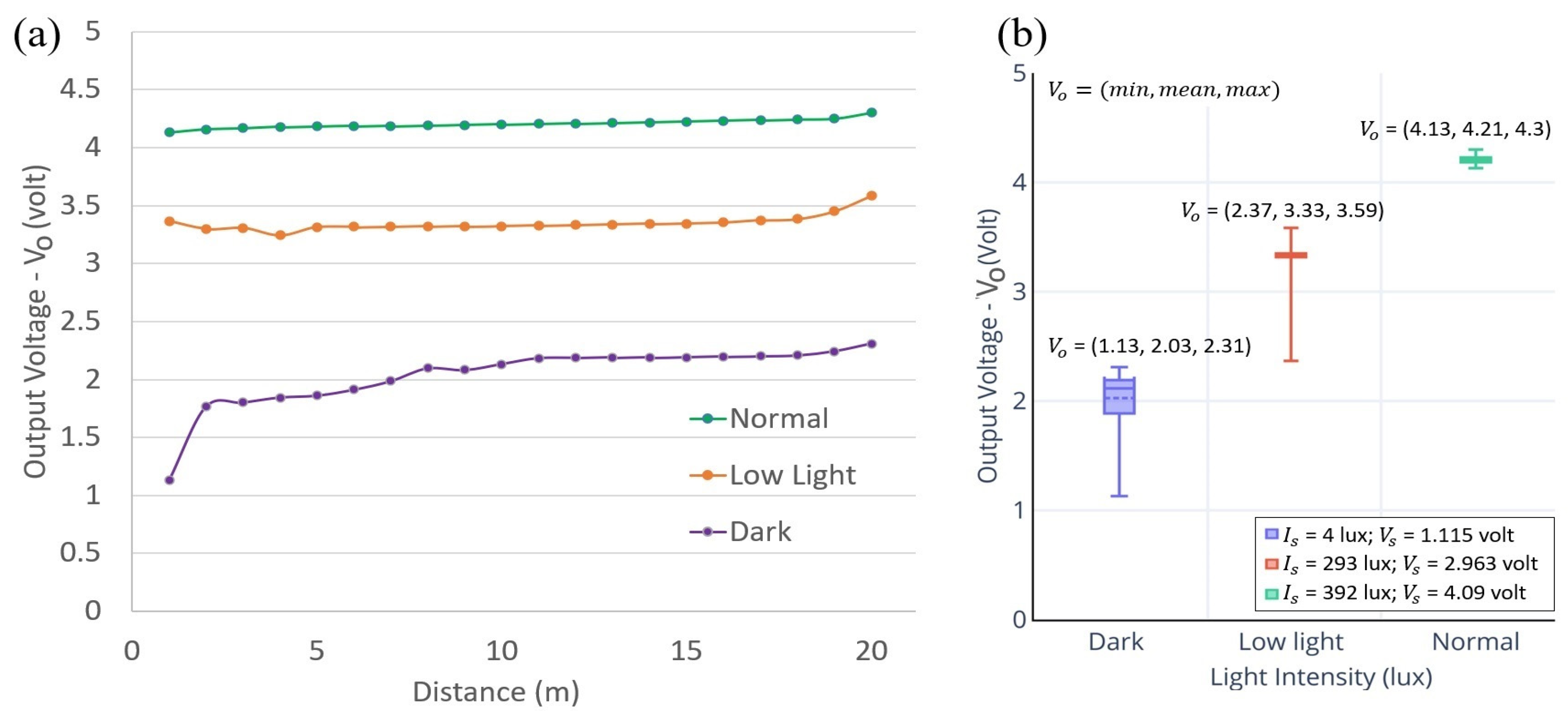
4.3. Capability of PGP as a Remote Monitoring System
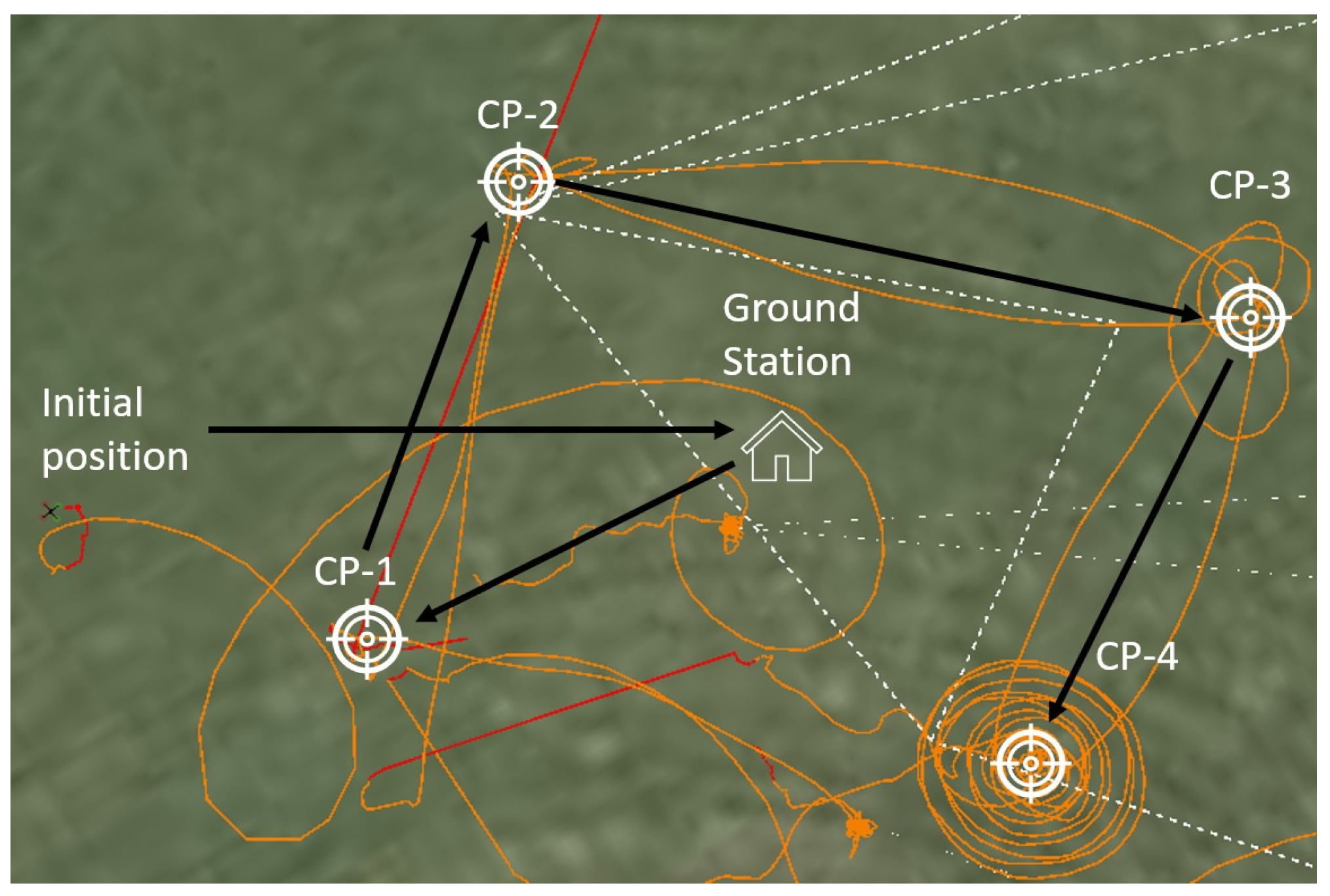
4.4. Validation and Testing in an Outdoor Environment
5. Conclusions
Author Contributions
Funding
Data Availability Statement
Acknowledgments
Conflicts of Interest
References
- Wang, X.; Yao, F.; Li, A.; Xu, Z.; Ding, L.; Yang, X.; Zhong, G.; Wang, S. DroneNet: Rescue Drone-View Object Detection. Drones 2023, 7, 441. [Google Scholar] [CrossRef]
- Shahmoradi, J.; Talebi, E.; Roghanchi, P.; Hassanalian, M.A. Comprehensive Review of Applications of Drone Technology in the Mining Industry. Drones 2020, 4, 34. [Google Scholar] [CrossRef]
- Mogili, U.R.; Deepak, B.B.V.L. Review on Application of Drone Systems in Precision Agriculture. Procedia Comput. Sci. 2018, 133, 502–509. [Google Scholar] [CrossRef]
- Mohd Daud, S.M.S.; Mohd Yusof, M.Y.P.; Heo, C.C.; Khoo, L.S.; Chainchel Singh, M.K.; Mahmood, M.S.; Nawawi, H. Applications of Drone in Disaster Management: A Scoping Review. Sci. Justice 2022, 62, 30–42. [Google Scholar] [CrossRef]
- Mohd Noor, N.; Abdullah, A.; Hashim, M. Remote Sensing UAV/Drones and Its Applications for Urban Areas: A Review. In Proceedings of the IOP Conference Series: Earth and Environmental Science, Kuala Lumpur, Malaysia, 24–25 April 2018. [Google Scholar] [CrossRef]
- Ali, H.; Hang, L.Y.; Suan, T.Y.; Polaiah, V.R.; Aluwi, M.I.F.; Zabidi, A.A.M.; Elshaikh, M. Development of Surveillance Drone Based Internet of Things (IoT) for Industrial Security Applications. In Proceedings of the Journal of Physics: Conference Series, Perlis, Malaysia, 19–20 October 2021. [Google Scholar] [CrossRef]
- Subbarayalu, V.; Vensuslaus, M.A. An Intrusion Detection System for Drone Swarming Utilizing Timed Probabilistic Automata. Drones 2023, 7, 248. [Google Scholar] [CrossRef]
- Alrayes, F.S.; Alotaibi, S.S.; Alissa, K.A.; Maashi, M.; Alhogail, A.; Alotaibi, N.; Mohsen, H.; Motwakel, A. Artificial Intelligence-Based Secure Communication and Classification for Drone-Enabled Emergency Monitoring Systems. Drones 2022, 6, 222. [Google Scholar] [CrossRef]
- Kumar, A.; Yadav, A.S.; Gill, S.S.; Pervaiz, H.; Ni, Q.; Buyya, R. A Secure Drone-to-Drone Communication and Software Defined Drone Network-Enabled Traffic Monitoring System. Simul. Model Pract. Theory 2022, 120, 102621. [Google Scholar] [CrossRef]
- Derpich, I.; Rey, C. Drone Optimization in Factory: Exploring the Minimal Level Vehicle Routing Problem for Efficient Material Distribution. Drones 2023, 7, 435. [Google Scholar] [CrossRef]
- Shah, S.A.; Lakho, G.M.; Keerio, H.A.; Sattar, M.N.; Hussain, G.; Mehdi, M.; Vistro, R.B.; Mahmoud, E.A.; Elansary, H.O. Application of Drone Surveillance for Advance Agriculture Monitoring by Android Application Using Convolution Neural Network. Agronomy 2023, 13, 1764. [Google Scholar] [CrossRef]
- Hafeez, A.; Husain, M.A.; Singh, S.P.; Chauhan, A.; Khan, M.T.; Kumar, N.; Chauhan, A.; Soni, S.K. Implementation of Drone Technology for Farm Monitoring and Pesticide Spraying: A Review. Inf. Process. Agric. 2023, 10, 192–203. [Google Scholar] [CrossRef]
- Iqbal, U.; Riaz, M.Z.B.; Zhao, J.; Barthelemy, J.; Perez, P. Drones for Flood Monitoring, Mapping and Detection: A Bibliometric Review. Drones 2023, 7, 32. [Google Scholar] [CrossRef]
- Benes, F.; Stasa, P.; Svub, J.; Alfian, G.; Kang, Y.S.; Rhee, J.T. Investigation of UHF Signal Strength Propagation at Warehouse Management Applications Based on Drones and RFID Technology Utilization. Appl. Sci. 2022, 12, 1277. [Google Scholar] [CrossRef]
- Juang, J.G.; Tu, G.T.; Liao, Y.H.; Huang, T.H.; Chang, S.I. Drone Patrol Using Thermal Imaging for Object Detection. Infrared Sens. Devices Appl. 2020, 11503, 1–7. [Google Scholar] [CrossRef]
- Xu, B.; Zhao, K.; Luo, Q.; Wu, G.; Pedrycz, W. A GV-Drone Arc Routing Approach for Urban Traffic Patrol by Coordinating a Ground Vehicle and Multiple Drones. Swarm Evol. Comput. 2023, 77, 101246. [Google Scholar] [CrossRef]
- Bollard, B.; Doshi, A.; Gilbert, N.; Poirot, C.; Gillman, L. Drone Technology for Monitoring Protected Areas in Remote and Fragile Environments. Drones 2022, 6, 42. [Google Scholar] [CrossRef]
- Li, Y.; Karim, M.M.; Qin, R. A Virtual-Reality-Based Training and Assessment System for Bridge Inspectors with an Assistant Drone. IEEE Trans. Hum. Mach. Syst. 2022, 52, 591–601. [Google Scholar] [CrossRef]
- Alwateer, M.; Loke, S.W.; Zuchowicz, A.M. Drone Services: Issues in Drones for Location-Based Services from Human-Drone Interaction to Information Processing. J. Locat. Based Serv. 2019, 13, 94–127. [Google Scholar] [CrossRef]
- Liu, Q.; He, Z.; Li, X.; Zheng, Y. PTB-TIR: A Thermal Infrared Pedestrian Tracking Benchmark. IEEE Trans. Multimed. 2020, 22, 666–675. [Google Scholar] [CrossRef]
- Guo, X.; Hu, Q. Low-Light Image Enhancement via Breaking Down the Darkness. Int. J. Comput. Vis. 2023, 131, 48–66. [Google Scholar] [CrossRef]
- Chen, Y.Y.; Jan, J.K.; Tsai, M.L.; Ku, C.C.; Huang, D.C. On the Security of RFID-Based Monitoring Mechanism for Retail Inventory Management. KSII Trans. Internet Inf. Syst. 2012, 6, 515–528. [Google Scholar] [CrossRef]
- Fernández-Caramés, T.M.; Fraga-Lamas, P.; Suárez-Albela, M.; Castedo, L. Reverse Engineering and Security Evaluation of Commercial Tags for RFID-Based IoT Applications. Sensors 2017, 17, 28. [Google Scholar] [CrossRef] [PubMed]
- Piciarelli, C.; Foresti, G.L. Drone Swarm Patrolling with Uneven Coverage Requirements. IET Comput. Vis. 2020, 14, 452–461. [Google Scholar] [CrossRef]
- Stolfi, D.H.; Brust, M.R.; Danoy, G.; Bouvry, P. CONSOLE: Intruder Detection Using a UAV Swarm and Security Rings. Swarm Intell. 2021, 15, 205–235. [Google Scholar] [CrossRef]
- Moltajaei Farid, A.; Mei Kuan, L.; Kamal, M.A.S.; Wong, K. Effective UAV Patrolling for Swarm of Intruders with Heterogeneous Behavior. Robotica 2023, 41, 1673–1688. [Google Scholar] [CrossRef]
- Patrinopoulou, N.; Daramouskas, I.; Meimetis, D.; Lappas, V.; Kostopoulos, V. A Multi-Agent System Using Decentralized Decision-Making Techniques for Area Surveillance and Intruder Monitoring. Drones 2022, 6, 357. [Google Scholar] [CrossRef]
- Yao, C.B.; Kao, C.Y.; Lin, J.T. Drone for Dynamic Monitoring and Tracking with Intelligent Image Analysis. Intell. Autom. Soft Comput. 2023, 36, 2233–2252. [Google Scholar] [CrossRef]
- Kakiuchi, R.; Tran, D.T.; Lee, J.H. Evaluation of Human Behaviour Detection and Interaction with Information Projection for Drone-Based Night-Time Security. Drones 2023, 7, 307. [Google Scholar] [CrossRef]
- Xiang, H.; Han, Y.; Pan, N.; Zhang, M.; Wang, Z. Study on Multi-UAV Cooperative Path Planning for Complex Patrol Tasks in Large Cities. Drones 2023, 7, 367. [Google Scholar] [CrossRef]
- Hassan, E.; Khalil, Y.; Ahmad, I. Learning Deep Feature Fusion for Traffic Light Detection. J. Eng. Res. 2023, in press. [Google Scholar] [CrossRef]
- Yang, L.; Ma, R.; Zakhor, A. Drone Object Detection Using RGB/IR Fusion. arXiv 2022, arXiv:2201.03786. [Google Scholar] [CrossRef]
- Kashiyama, T.; Sobue, H.; Sekimoto, Y. Sky Monitoring System for Flying Object Detection Using 4k Resolution Camera. Sensors 2020, 20, 7071. [Google Scholar] [CrossRef] [PubMed]
- Sarhan, N.H.; Al-Omary, A.Y. Traffic Light Detection Using OpenCV and YOLO. In Proceedings of the 2022 International Conference on Innovation and Intelligence for Informatics, Computing, and Technologies, Bahrain, 20 November 2022. [Google Scholar] [CrossRef]
- Niu, C.; Li, K. Traffic Light Detection and Recognition Method Based on YOLOv5s and AlexNet. Appl. Sci. 2022, 12, 10808. [Google Scholar] [CrossRef]
- Wang, Q.; Zhang, Q.; Liang, X.; Wang, Y.; Zhou, C.; Mikulovich, V.I. Traffic Lights Detection and Recognition Method Based on the Improved Yolov4 Algorithm. Sensors 2022, 22, 200. [Google Scholar] [CrossRef] [PubMed]
- Massetti, L.; Paterni, M.; Merlino, S. Monitoring Light Pollution with an Unmanned Aerial Vehicle: A Case Study Comparing RGB Images and Night Ground Brightness. Remote Sens. 2022, 14, 2052. [Google Scholar] [CrossRef]


| Environmental Light Intensity (lux) | Detection Range (m) | ||
|---|---|---|---|
| Triangle | Square | Pentagon | |
| 14 | 20.5 | 15.3 | |
| 13 | 18.4 | 14.3 | |
| 10.1 | 17 | 12.5 | |
Disclaimer/Publisher’s Note: The statements, opinions and data contained in all publications are solely those of the individual author(s) and contributor(s) and not of MDPI and/or the editor(s). MDPI and/or the editor(s) disclaim responsibility for any injury to people or property resulting from any ideas, methods, instructions or products referred to in the content. |
© 2023 by the authors. Licensee MDPI, Basel, Switzerland. This article is an open access article distributed under the terms and conditions of the Creative Commons Attribution (CC BY) license (https://creativecommons.org/licenses/by/4.0/).
Share and Cite
Kuantama, E.; Seth, A.; James, A.; Zhang, Y. Flying Watchdog-Based Guard Patrol with Check Point Data Verification. Future Internet 2023, 15, 340. https://doi.org/10.3390/fi15100340
Kuantama E, Seth A, James A, Zhang Y. Flying Watchdog-Based Guard Patrol with Check Point Data Verification. Future Internet. 2023; 15(10):340. https://doi.org/10.3390/fi15100340
Chicago/Turabian StyleKuantama, Endrowednes, Avishkar Seth, Alice James, and Yihao Zhang. 2023. "Flying Watchdog-Based Guard Patrol with Check Point Data Verification" Future Internet 15, no. 10: 340. https://doi.org/10.3390/fi15100340