
Biomimetic Electrospun Self-Assembling Peptide Scaffolds for Neural Stem Cell Transplantation in Neural Tissue Engineering
 ,
,  ,
,
Abstract
:1. Introduction
2. Material and Methods
2.1. Materials and Preparation
2.1.1. Materials
2.1.2. Synthesis and Purification of Self-Assembly Peptides
2.1.3. Crosslinked SAP Preparation
2.1.4. Electrospinning of Crosslinked SAPs
2.1.5. Post-Treatment
2.2. Characterization
2.2.1. Scanning Electron Microscope (SEM)
2.2.2. Fourier Transform Infrared (FTIR)
2.2.3. Ninhydrin Test
2.2.4. Fluorescence Intensity Test
2.3. Neural Stem Cells (NSCs) Culture
2.3.1. Two-Dimensional Scaffold In Vitro Test: Cell Viability and Differentiation Assay
2.3.2. Three-Dimensional Scaffold In Vitro Test: Cell Viability and Differentiation Assay
2.3.3. Implantation of Microchannels into the Spinal Cord Tissue of Rodents (Experimental Setup)
2.3.4. Immunohistochemistry
2.4. Statistical Analysis
3. Result
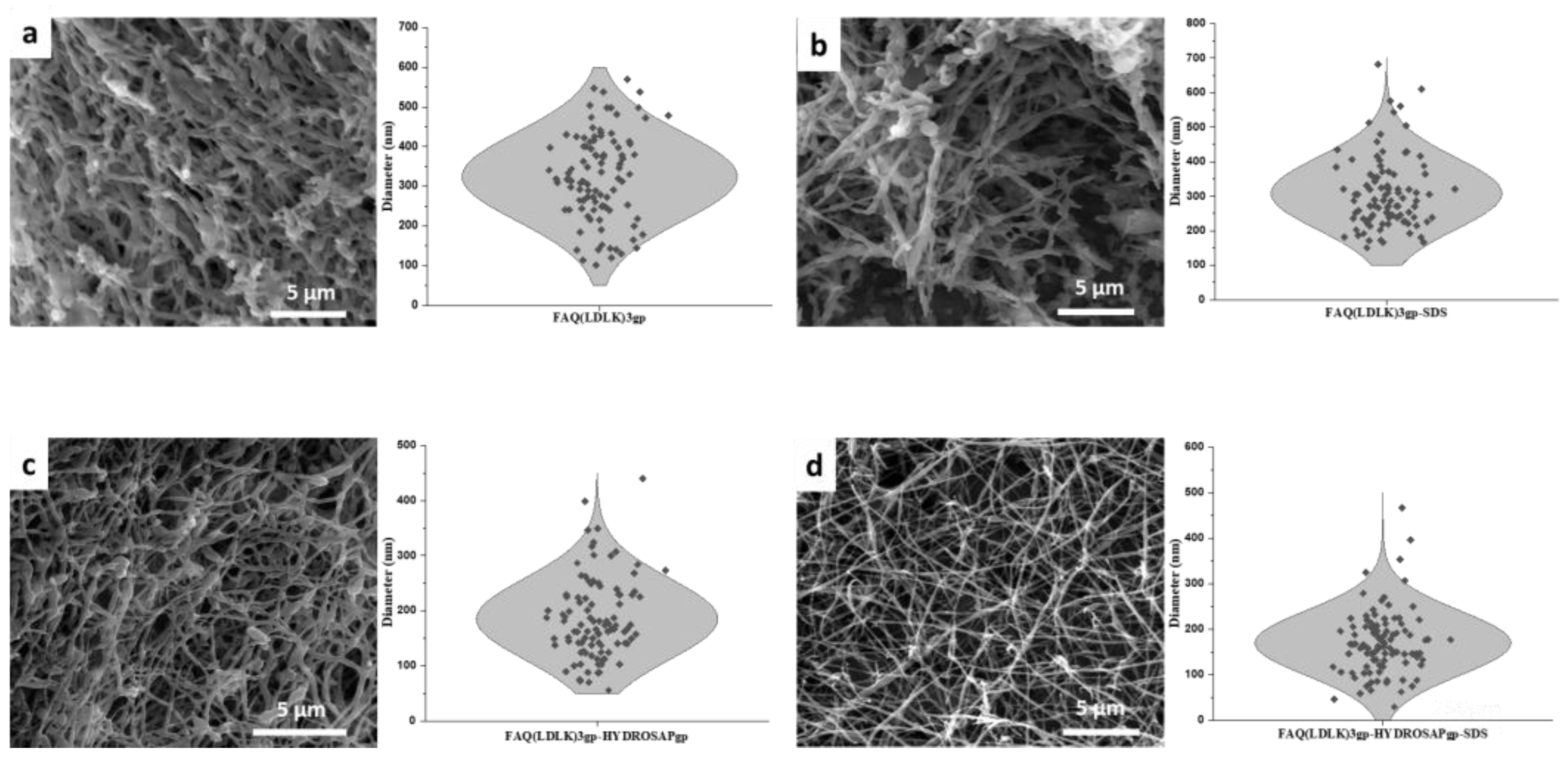
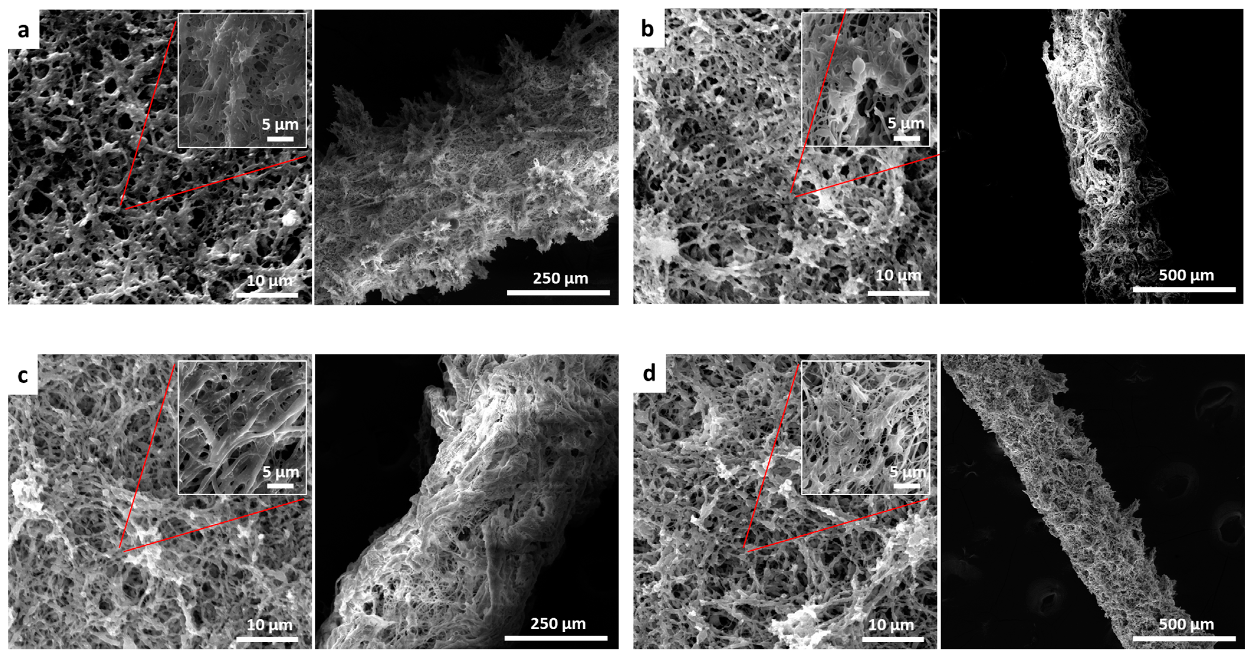
3.1. Morphology
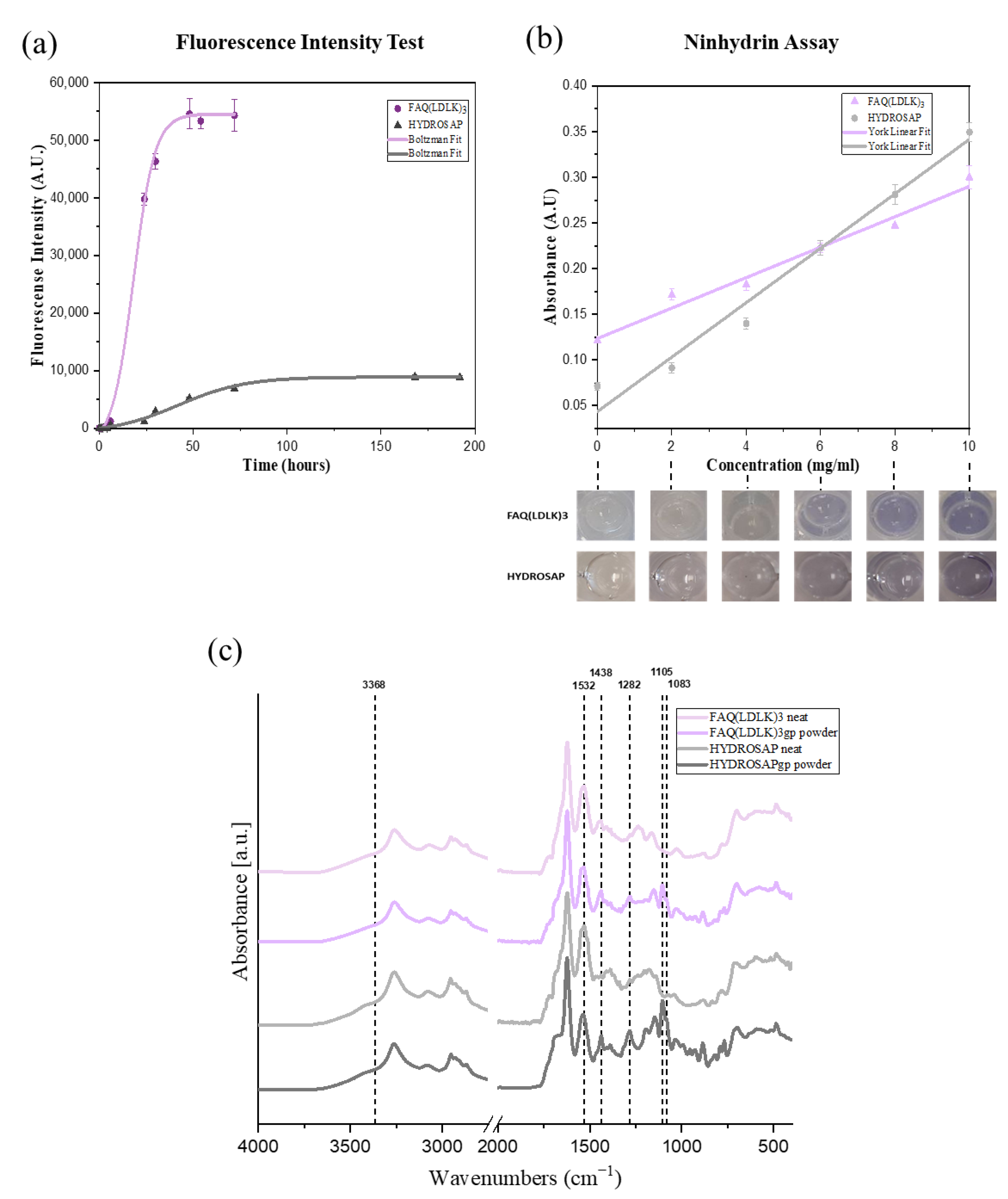
3.2. Genipin Crosslinking
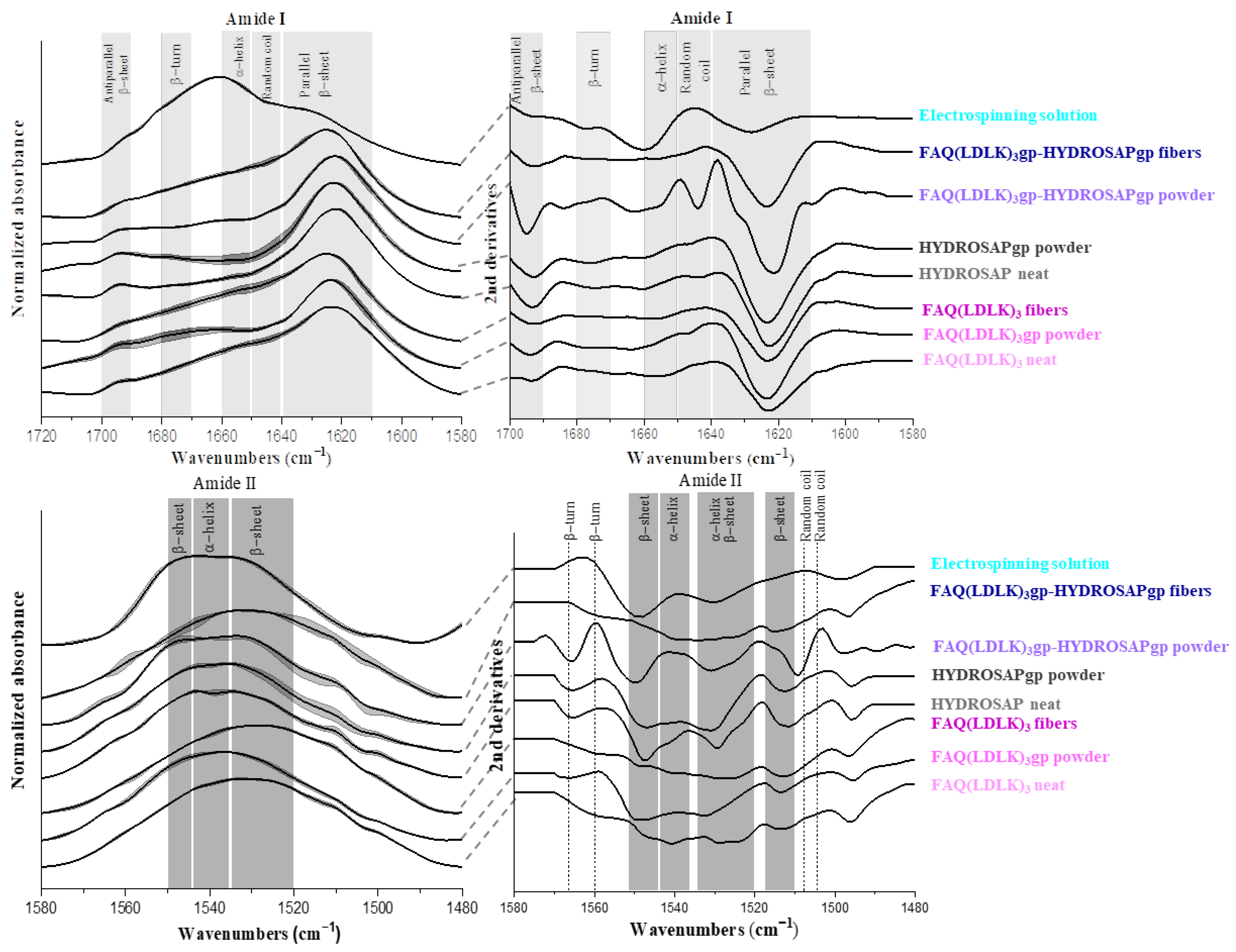
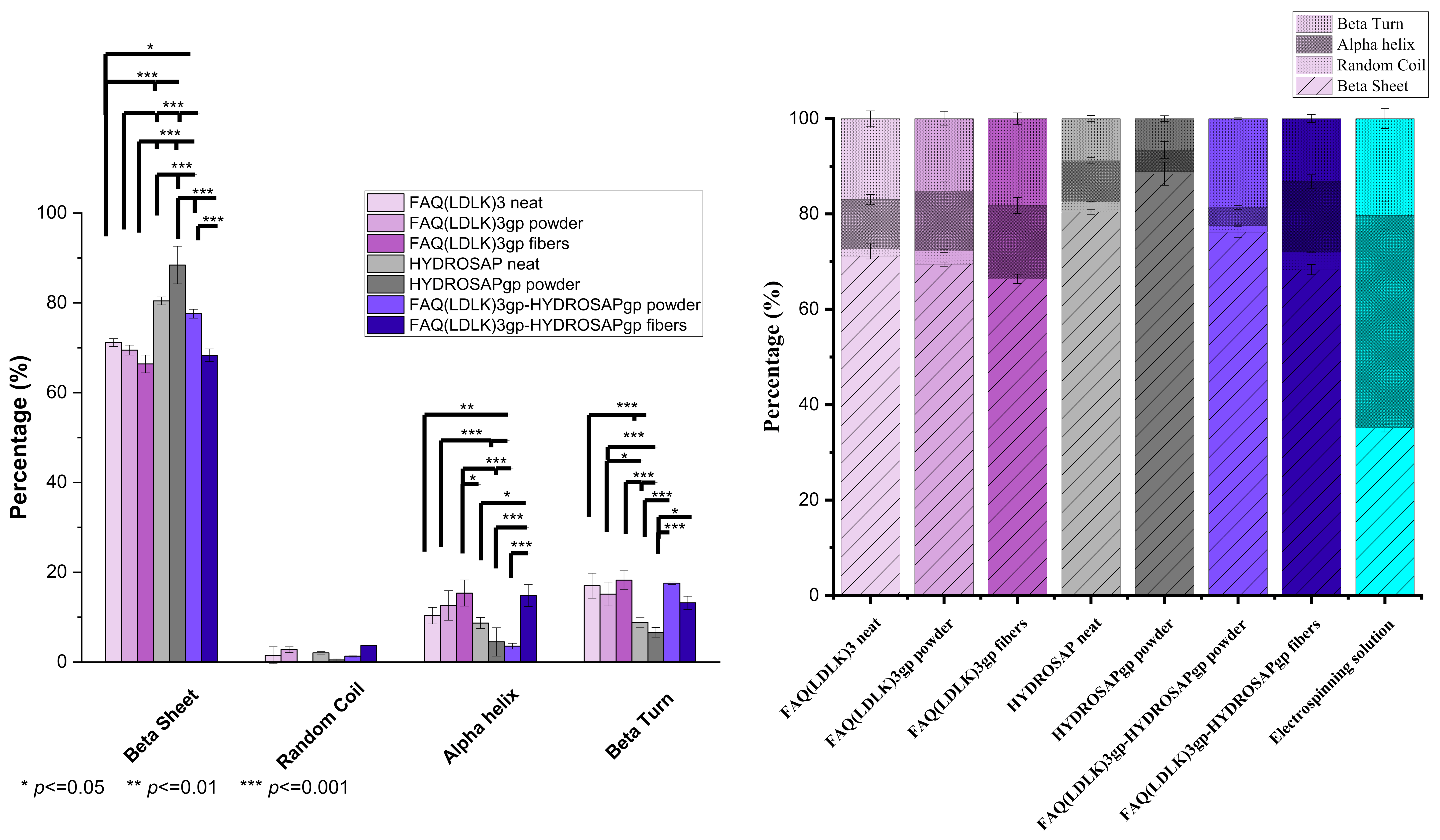
3.3. Secondary Structure Components (FTIR)
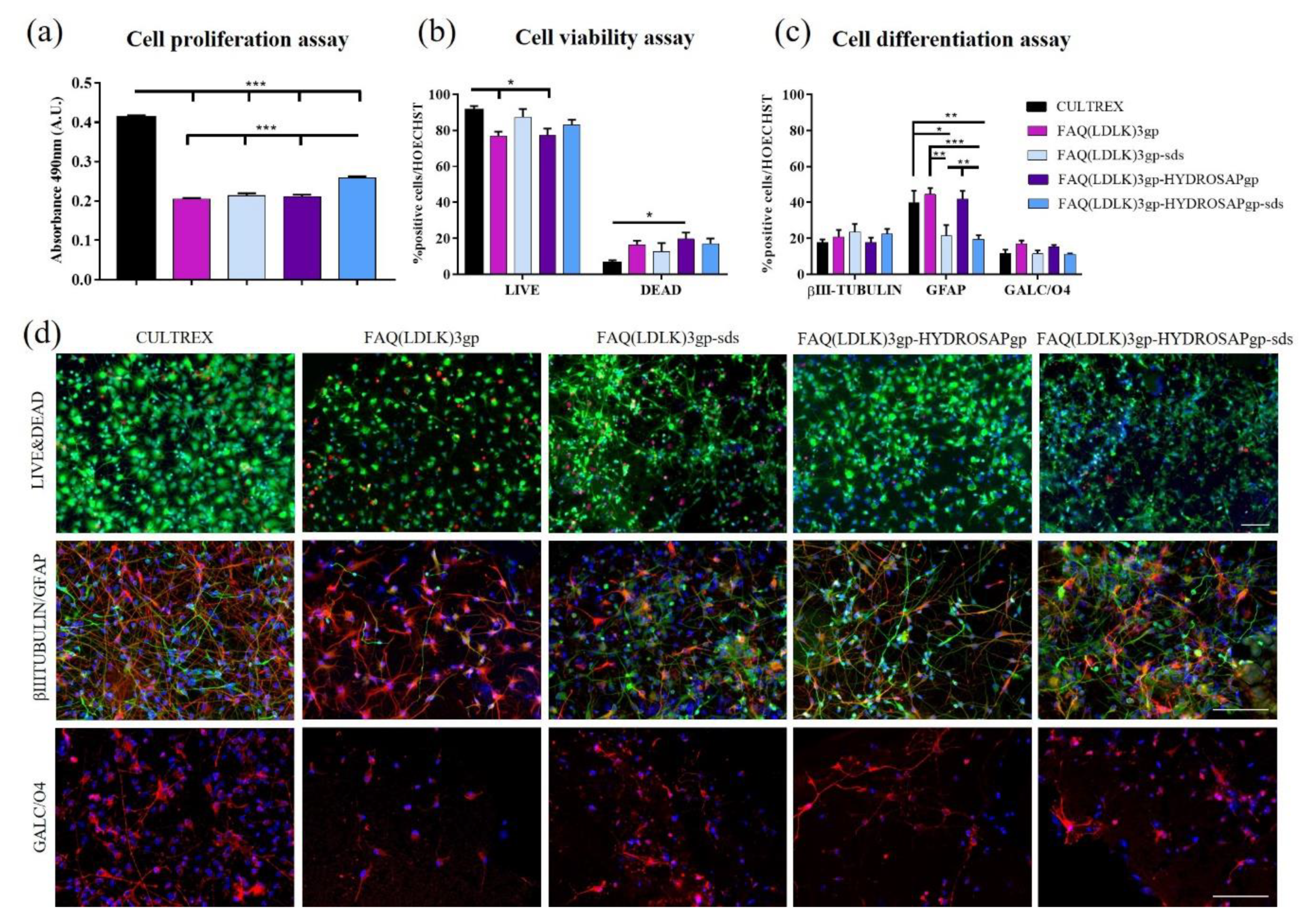
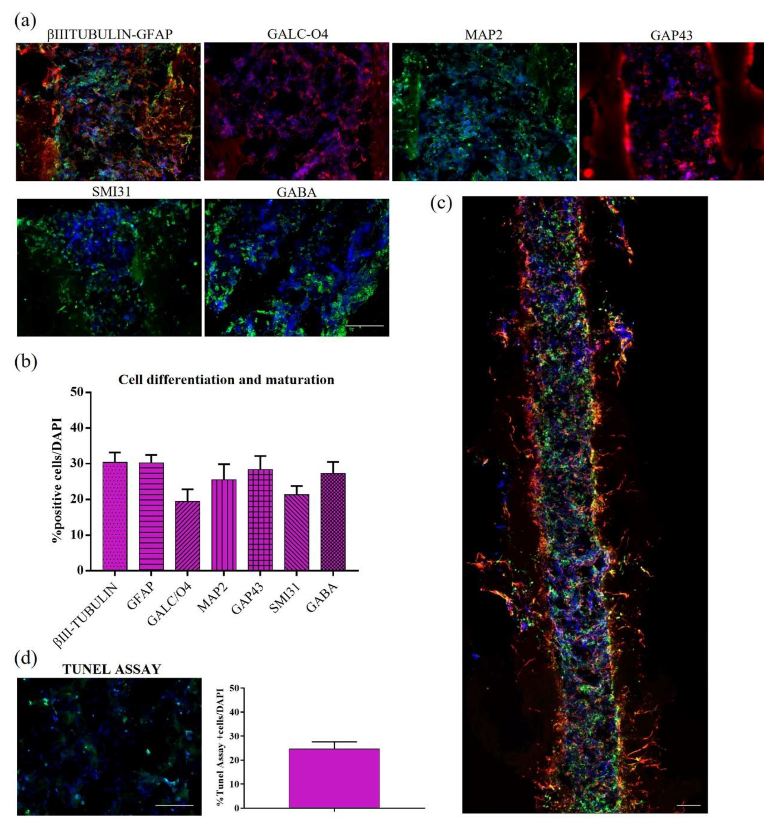
3.4. Two-Dimensional and Three-Dimensional In Vitro Cell Cultures
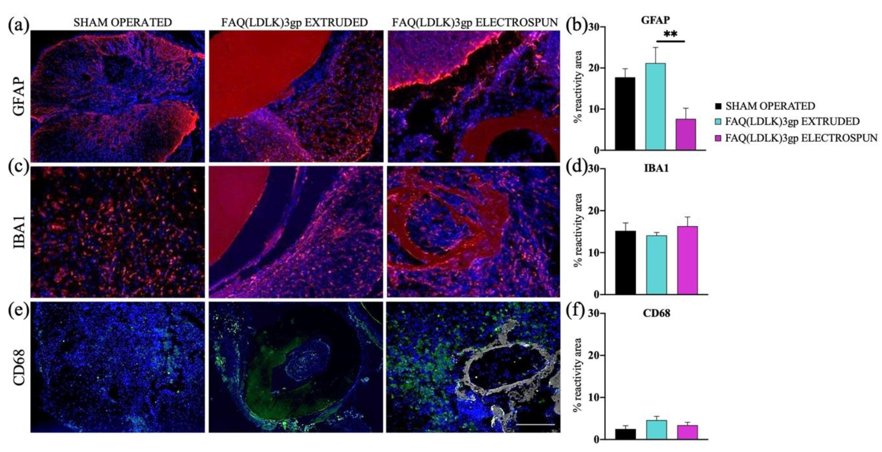
3.5. Biocompatibility (Animal Testing Outcomes)
4. Discussion
5. Conclusions
Supplementary Materials
Author Contributions
Funding
Institutional Review Board Statement
Informed Consent Statement
Data Availability Statement
Acknowledgments
Conflicts of Interest
Abbreviations
| SAPs | Self-assembling peptides |
| ECM | Extra cellular matrix |
| hNSCs | human neural stem cells |
| mNSC | murine neural stem cells |
| FTIR | Fourier transform infrared |
| SEM | Scanning electron microscope |
| SDS | Sodium dodecyl sulfate |
| HFIP | Hexafluoroisopropanol |
| TFA | Trifluoroacetic acid |
| DMF | Dimethyl formamide |
| EtOH | Ethanol |
| HCl | Hydrochloric acid |
| PBS | Phosphate-buffered saline |
| Oxyma | ethyl 2-cyano-2-(hydroxymino)acetate |
| DIC | N,N′-Diisopropylcarbodiimide |
References
- Wang, T.; Nanda, S.S.; Papaefthymiou, G.C.; Yi, D.K. Mechanophysical Cues in Extracellular Matrix Regulation of Cell Behavior. ChemBioChem 2020, 21, 1254–1264. [Google Scholar] [CrossRef]
- Kusindarta, D.L.; Wihadmadyatami, H. The role of extracellular matrix in tissue regeneration. In Tissue Regeneration; IntechOpen: London, UK, 2018. [Google Scholar] [CrossRef]
- Onuwaje, I.; Phillips, J.B. Three-dimensional culture systems in central nervous system research. In Handbook of Innovations in Central Nervous System Regenerative Medicine; Elsevier: Amsterdam, The Netherlands, 2020; pp. 571–601. [Google Scholar]
- Kharbikar, B.N.; Mohindra, P.; Desai, T.A. Biomaterials to enhance stem cell transplantation. Cell Stem Cell 2022, 29, 692–721. [Google Scholar] [CrossRef]
- de Freria, C.M.; Van Niekerk, E.; Blesch, A.; Lu, P. Neural Stem Cells: Promoting Axonal Regeneration and Spinal Cord Connectivity. Cells 2021, 10, 3296. [Google Scholar] [CrossRef] [PubMed]
- Ashammakhi, N.; Kim, H.-J.; Ehsanipour, A.; Bierman, R.D.; Kaarela, O.; Xue, C.; Khademhosseini, A.; Seidlits, S.K. Regenerative Therapies for Spinal Cord Injury. Tissue Eng. Part B Rev. 2019, 25, 471–491. [Google Scholar] [CrossRef] [PubMed]
- Wagner, F.B.; Mignardot, J.-B.; Le Goff-Mignardot, C.G.; Demesmaeker, R.; Komi, S.; Capogrosso, M.; Rowald, A.; Seáñez, I.; Caban, M.; Pirondini, E.; et al. Targeted neurotechnology restores walking in humans with spinal cord injury. Nature 2018, 563, 65–71. [Google Scholar] [CrossRef]
- Lewis, D. Electrical stimulation helps paralysed people walk again—And now we know why. Nature 2022, 611, 438. [Google Scholar] [CrossRef]
- Kathe, C.; Skinnider, M.A.; Hutson, T.H.; Regazzi, N.; Gautier, M.; Demesmaeker, R.; Komi, S.; Ceto, S.; James, N.D.; Cho, N.; et al. The neurons that restore walking after paralysis. Nature 2022, 611, 540–547. [Google Scholar] [CrossRef]
- Rosenzweig, E.S.; Brock, J.H.; Lu, P.; Kumamaru, H.; Salegio, E.A.; Kadoya, K.; Weber, J.L.; Liang, J.J.; Moseanko, R.; Hawbecker, S.; et al. Restorative effects of human neural stem cell grafts on the primate spinal cord. Nat. Med. 2018, 24, 484–490. [Google Scholar] [CrossRef] [PubMed]
- Kadoya, K.; Lu, P.; Nguyen, K.; Lee-Kubli, C.; Kumamaru, H.; Yao, L.; Knackert, J.; Poplawski, G.; Dulin, J.N.; Strobl, H.; et al. Spinal cord reconstitution with homologous neural grafts enables robust corticospinal regeneration. Nat. Med. 2016, 22, 479–487. [Google Scholar] [CrossRef]
- Lu, P.; Wang, Y.; Graham, L.; McHale, K.; Gao, M.; Wu, D.; Brock, J.; Blesch, A.; Rosenzweig, E.S.; Havton, L.A.; et al. Long-Distance Growth and Connectivity of Neural Stem Cells after Severe Spinal Cord Injury. Cell 2012, 150, 1264–1273. [Google Scholar] [CrossRef]
- Pugliese, R.; Maleki, M.; Zuckermann, R.N.; Gelain, F. Self-assembling peptides cross-linked with genipin: Resilient hydrogels and self-standing electrospun scaffolds for tissue engineering applications. Biomater. Sci. 2019, 7, 76–91. [Google Scholar] [CrossRef] [PubMed]
- Zhao, X.; Cui, K.; Li, Z. The role of biomaterials in stem cell-based regenerative medicine. Futur. Med. Chem. 2019, 11, 1777–1790. [Google Scholar] [CrossRef]
- Gattazzo, F.; Urciuolo, A.; Bonaldo, P. Extracellular matrix: A dynamic microenvironment for stem cell niche. Biochim. Biophys. Acta (BBA)—Gen. Subj. 2014, 1840, 2506–2519. [Google Scholar] [CrossRef]
- Adu-Berchie, K.; Mooney, D.J. Biomaterials as Local Niches for Immunomodulation. Acc. Chem. Res. 2020, 53, 1749–1760. [Google Scholar] [CrossRef]
- Raspa, A.; Carminati, L.; Pugliese, R.; Fontana, F.; Gelain, F. Self-assembling peptide hydrogels for the stabilization and sustained release of active Chondroitinase ABC in vitro and in spinal cord injuries. J. Control. Release 2021, 330, 1208–1219. [Google Scholar] [CrossRef]
- Mitrousis, N.; Fokina, A.; Shoichet, M.S. Biomaterials for cell transplantation. Nat. Rev. Mater. 2018, 3, 441–456. [Google Scholar] [CrossRef]
- Kapałczyńska, M.; Kolenda, T.; Przybyła, W.; Zajączkowska, M.; Teresiak, A.; Filas, V.; Ibbs, M.; Bliźniak, R.; Łuczewski, L.; Lamperska, K. 2D and 3D cell cultures—A comparison of different types of cancer cell cultures. Arch. Med. Sci. 2016, 14, 910–919. [Google Scholar] [CrossRef]
- Jensen, C.; Teng, Y. Is It Time to Start Transitioning from 2D to 3D Cell Culture? Front. Mol. Biosci. 2020, 7, 33. [Google Scholar] [CrossRef] [PubMed]
- de Lima, G.G.; Lyons, S.; Devine, D.M.; Nugent, M.J.D. Electrospinning of Hydrogels for Biomedical Applications; Springer: Berlin/Heidelberg, Germany, 2018; pp. 219–258. [Google Scholar] [CrossRef]
- Cembran, A.; Bruggeman, K.F.; Williams, R.J.; Parish, C.L.; Nisbet, D.R. Biomimetic Materials and Their Utility in Modeling the 3-Dimensional Neural Environment. iScience 2020, 23, 100788. [Google Scholar] [CrossRef] [PubMed]
- Gelain, F.; Luo, Z.; Zhang, S. Self-Assembling Peptide EAK16 and RADA16 Nanofiber Scaffold Hydrogel. Chem. Rev. 2020, 120, 13434–13460. [Google Scholar] [CrossRef]
- Chen, J.; Zou, X. Self-assemble peptide biomaterials and their biomedical applications. Bioact. Mater. 2019, 4, 120–131. [Google Scholar] [CrossRef] [PubMed]
- Mendes, A.C.; Stephansen, K.; Chronakis, I.S. Electrospinning of food proteins and polysaccharides. Food Hydrocoll. 2017, 68, 53–68. [Google Scholar] [CrossRef]
- Nivison-Smith, L.; Rnjak, J.; Weiss, A.S. Synthetic human elastin microfibers: Stable cross-linked tropoelastin and cell interactive constructs for tissue engineering applications. Acta Biomater. 2010, 6, 354–359. [Google Scholar] [CrossRef] [PubMed]
- Maleki, M.; Natalello, A.; Pugliese, R.; Gelain, F. Fabrication of nanofibrous electrospun scaffolds from a heterogeneous library of co- and self-assembling peptides. Acta Biomater. 2017, 51, 268–278. [Google Scholar] [CrossRef]
- Khadka, D.B.; Haynie, D.T. Protein- and peptide-based electrospun nanofibers in medical biomaterials. Nanomed. Nanotechnol. Biol. Med. 2012, 8, 1242–1262. [Google Scholar] [CrossRef] [PubMed]
- Kim, K.; Kloxin, C.J.; Saven, J.G.; Pochan, D.J. Nanofibers Produced by Electrospinning of Ultrarigid Polymer Rods Made from Designed Peptide Bundlemers. ACS Appl. Mater. Interfaces 2021, 13, 26339–26351. [Google Scholar] [CrossRef] [PubMed]
- Hamedani, Y.; Macha, P.; Evangelista, E.L.; Sammeta, V.R.; Chalivendra, V.; Rasapalli, S.; Vasudev, M.C. Electrospinning of tyrosine-based oligopeptides: Self-assembly or forced assembly? J. Biomed. Mater. Res. Part A 2020, 108, 829–838. [Google Scholar] [CrossRef]
- Bucci, R.; Georgilis, E.; Bittner, A.M.; Gelmi, M.L.; Clerici, F. Peptide-Based Electrospun Fibers: Current Status and Emerging Developments. Nanomaterials 2021, 11, 1262. [Google Scholar] [CrossRef] [PubMed]
- Nuansing, W.; Frauchiger, D.; Huth, F.; Rebollo, A.; Hillenbrand, R.; Bittner, A.M. Electrospinning of peptide and protein fibres: Approaching the molecular scale. Faraday Discuss. 2013, 166, 209–221. [Google Scholar] [CrossRef] [PubMed]
- Pugliese, R.; Fontana, F.; Marchini, A.; Gelain, F. Branched peptides integrate into self-assembled nanostructures and enhance biomechanics of peptidic hydrogels. Acta Biomater. 2018, 66, 258–271. [Google Scholar] [CrossRef]
- Marchini, A.; Raspa, A.; Pugliese, R.; El Malek, M.A.; Pastori, V.; Lecchi, M.; Vescovi, A.L.; Gelain, F. Multifunctionalized hydrogels foster hNSC maturation in 3D cultures and neural regeneration in spinal cord injuries. Proc. Natl. Acad. Sci. USA 2019, 116, 7483–7492. [Google Scholar] [CrossRef]
- Zhang, K.; Qian, Y.; Wang, H.; Fan, L.; Huang, C.; Yin, A.; Mo, X. Genipin-crosslinked silk fibroin/hydroxybutyl chitosan nanofibrous scaffolds for tissue-engineering application. J. Biomed. Mater. Res. Part A 2010, 95, 870–881. [Google Scholar] [CrossRef]
- Zeng, S.; Ye, M.; Qiu, J.; Fang, W.; Rong, M.; Guo, Z.; Gao, W. Preparation and characterization of genipin-cross-linked silk fibroin/chitosan sustained-release microspheres. Drug Des. Dev. Ther. 2015, 9, 2501–2514. [Google Scholar] [CrossRef] [PubMed]
- Sadat, A.; Joye, I.J. Peak Fitting Applied to Fourier Transform Infrared and Raman Spectroscopic Analysis of Proteins. Appl. Sci. 2020, 10, 5918. [Google Scholar] [CrossRef]
- Raspa, A.; Saracino, G.A.A.; Pugliese, R.; Silva, D.; Cigognini, D.; Vescovi, A.; Gelain, F. Complementary Co-assembling Peptides: From In Silico Studies to In Vivo Application. Adv. Funct. Mater. 2014, 24, 6317–6328. [Google Scholar] [CrossRef]
- Marchini, A.; Favoino, C.; Gelain, F. Multi-Functionalized Self-Assembling Peptides as Reproducible 3D Cell Culture Systems Enabling Differentiation and Survival of Various Human Neural Stem Cell Lines. Front. Neurosci. 2020, 14, 413. [Google Scholar] [CrossRef] [PubMed]
- Butler, M.F.; Ng, Y.-F.; Pudney, P.D.A. Mechanism and kinetics of the crosslinking reaction between biopolymers containing primary amine groups and genipin. J. Polym. Sci. Part A Polym. Chem. 2003, 41, 3941–3953. [Google Scholar] [CrossRef]
- Roy, S.; Rhim, J.-W. Genipin-Crosslinked Gelatin/Chitosan-Based Functional Films Incorporated with Rosemary Essential Oil and Quercetin. Materials 2022, 15, 3769. [Google Scholar] [CrossRef] [PubMed]
- Friedman, M. Applications of the Ninhydrin Reaction for Analysis of Amino Acids, Peptides, and Proteins to Agricultural and Biomedical Sciences. J. Agric. Food Chem. 2004, 52, 385–406. [Google Scholar] [CrossRef]
- Zatorski, J.M.; Montalbine, A.N.; Ortiz-Cárdenas, J.E.; Pompano, R.R. Quantification of fractional and absolute functionalization of gelatin hydrogels by optimized ninhydrin assay and 1H NMR. Anal. Bioanal. Chem. 2020, 412, 6211–6220. [Google Scholar] [CrossRef]
- Zhang, Y.; Wang, Q.-S.; Yan, K.; Qi, Y.; Wang, G.-F.; Cui, Y.-L. Preparation, characterization, and evaluation of genipin crosslinked chitosan/gelatin three-dimensional scaffolds for liver tissue engineering applications. J. Biomed. Mater. Res. Part A 2016, 104, 1863–1870. [Google Scholar] [CrossRef] [PubMed]
- Di Foggia, M.; Taddei, P.; Torreggiani, A.; Dettin, M.; Tinti, A. Self-Assembling Peptides for Biomedical Applications: IR and Raman Spectroscopies for the Study of Secondary Structure. Proteom. Res. J. 2012, 2, 231–272. [Google Scholar]
- Barth, A. Infrared spectroscopy of proteins. Biochim. Biophys. Acta Bioenerg. 2007, 1767, 1073–1101. [Google Scholar] [CrossRef]
- Kong, J.; Yu, S. Fourier Transform Infrared Spectroscopic Analysis of Protein Secondary Structures. Acta Biochim. Biophys. Sin. 2007, 39, 549–559. [Google Scholar] [CrossRef]
- Mazzini, L.; Gelati, M.; Profico, D.C.; Sorarù, G.; Ferrari, D.; Copetti, M.; Muzi, G.; Ricciolini, C.; Carletti, S.; Giorgi, C.; et al. Results from Phase I Clinical Trial with Intraspinal Injection of Neural Stem Cells in Amyotrophic Lateral Sclerosis: A Long-Term Outcome. Stem Cells Transl. Med. 2019, 8, 887–897. [Google Scholar] [CrossRef]
- Forouharshad, M.; King, S.G.; Buxton, W.; Kunovski, P.; Stolojan, V. Textile-Compatible, Electroactive Polyvinylidene Fluoride Electrospun Mats for Energy Harvesting. Macromol. Chem. Phys. 2019, 220, 1900364. [Google Scholar] [CrossRef]
- Zheng, J.-Y.; Zhuang, M.-F.; Yu, Z.-J.; Zheng, G.-F.; Zhao, Y.; Wang, H.; Sun, D.-H. The Effect of Surfactants on the Diameter and Morphology of Electrospun Ultrafine Nanofiber. J. Nanomater. 2014, 2014, 689298. [Google Scholar] [CrossRef]
- Gardella, L.; Forouharshad, M.; Pastorino, L.; Monticelli, O. Hyperbranched PDLA-polyglicerol: A novel additive for tuning PLLA electrospun fiber degradation and properties. Eur. Polym. J. 2017, 91, 21–30. [Google Scholar] [CrossRef]
- Han, S.; Nie, K.; Li, J.; Sun, Q.; Wang, X.; Li, X.; Li, Q. 3D Electrospun Nanofiber-Based Scaffolds: From Preparations and Properties to Tissue Regeneration Applications. Stem Cells Int. 2021, 2021, 8790143. [Google Scholar] [CrossRef] [PubMed]
- Gelain, F.; Cigognini, D.; Caprini, A.; Silva, D.; Colleoni, B.; Donegá, M.; Antonini, S.; Cohen, B.E.; Vescovi, A. New bioactive motifs and their use in functionalized self-assembling peptides for NSC differentiation and neural tissue engineering. Nanoscale 2012, 4, 2946–2957. [Google Scholar] [CrossRef]
- Pugliese, R.; Marchini, A.; Saracino, G.A.A.; Zuckermann, R.N.; Gelain, F. Cross-linked self-assembling peptide scaffolds. Nano Res. 2018, 11, 586–602. [Google Scholar] [CrossRef]
- Tian, L.; Prabhakaran, M.P.; Ramakrishna, S. Strategies for regeneration of components of nervous system: Scaffolds, cells and biomolecules. Regen. Biomater. 2015, 2, 31–45. [Google Scholar] [CrossRef] [PubMed]
- Behtaj, S.; John, J.A.S.; Ekberg, J.A.K.; Rybachuk, M. Neuron-fibrous scaffold interfaces in the peripheral nervous system: A perspective on the structural requirements. Neural Regen. Res. 2022, 17, 1893–1897. [Google Scholar] [CrossRef] [PubMed]
- Anderson, J.M.; Rodriguez, A.; Chang, D.T. Foreign body reaction to biomaterials. Semin. Immunol. 2008, 20, 86–100. [Google Scholar] [CrossRef]
- Westerman, M.; Spencer, J.; Collet, C. Chromosomal localization of the gene for late lactation protein (LLP) in the tammar wallaby (Macropus eugenii). Cytogenet. Genome Res. 1991, 56, 182–184. [Google Scholar] [CrossRef]
- Morais, J.M.; Papadimitrakopoulos, F.; Burgess, D.J. Biomaterials/Tissue Interactions: Possible Solutions to Overcome Foreign Body Response. AAPS J. 2010, 12, 188–196. [Google Scholar] [CrossRef]
- de Jong, E.K.; Dijkstra, I.M.; Hensens, M.; Brouwer, N.; van Amerongen, M.; Liem, R.S.B.; Boddeke, H.W.G.M.; Biber, K. Vesicle-Mediated Transport and Release of CCL21 in Endangered Neurons: A Possible Explanation for Microglia Activation Remote from a Primary Lesion. J. Neurosci. 2005, 25, 7548–7557. [Google Scholar] [CrossRef]
- Perale, G.; Rossi, F.; Sundstrom, E.; Bacchiega, S.; Masi, M.; Forloni, G.; Veglianese, P. Hydrogels in Spinal Cord Injury Repair Strategies. ACS Chem. Neurosci. 2011, 2, 336–345. [Google Scholar] [CrossRef]
- Batchelor, P.E.; Liberatore, G.T.; Wong, J.Y.F.; Porritt, M.J.; Frerichs, F.; Donnan, G.A.; Howells, D.W. Activated Macrophages and Microglia Induce Dopaminergic Sprouting in the Injured Striatum and Express Brain-Derived Neurotrophic Factor and Glial Cell Line-Derived Neurotrophic Factor. J. Neurosci. 1999, 19, 1708–1716. [Google Scholar] [CrossRef]
- Nagamoto-Combs, K.; Morecraft, R.J.; Darling, W.G.; Combs, C.K.; Orihuela, R.; McPherson, C.A.; Harry, G.J.; Manocha, G.D.; Puig, K.; Spejo, A.B.; et al. Long-Term Gliosis and Molecular Changes in the Cervical Spinal Cord of the Rhesus Monkey after Traumatic Brain Injury. J. Neurotrauma 2010, 27, 565–585. [Google Scholar] [CrossRef]
- Okada, S.; Hara, M.; Kobayakawa, K.; Matsumoto, Y.; Nakashima, Y. Astrocyte reactivity and astrogliosis after spinal cord injury. Neurosci. Res. 2018, 126, 39–43. [Google Scholar] [CrossRef]
- Lukovic, D.; Stojkovic, M.; Moreno-Manzano, V.; Jendelova, P.; Sykova, E.; Bhattacharya, S.S.; Erceg, S. Concise Review: Reactive Astrocytes and Stem Cells in Spinal Cord Injury: Good Guys or Bad Guys? Stem Cells 2015, 33, 1036–1041. [Google Scholar] [CrossRef] [PubMed]
- Low, W.C.; Rujitanaroj, P.O.; Lee, D.K.; Messersmith, P.B.; Stanton, L.W.; Goh, E.; Chew, S.Y. Nanofibrous scaffold-mediated REST knockdown to enhance neuronal differentiation of stem cells. Biomaterials 2013, 34, 3581–3590. [Google Scholar] [CrossRef]
- Raspa, A.; Gelain, F. Mimicking Extracellular Matrix via Engineered Nanostructured Biomaterials for Neural Repair. Curr. Neuropharmacol. 2021, 19, 2110–2124. [Google Scholar] [CrossRef] [PubMed]
- Fang, A.; Li, D.; Hao, Z.; Wang, L.; Pan, B.; Gao, L.; Qu, X.; He, J. Effects of astrocyte on neuronal outgrowth in a layered 3D structure. Biomed. Eng. Online 2019, 18, 74. [Google Scholar] [CrossRef]
- Hu, Y.; Huang, G.; Tian, J.; Qiu, J.; Jia, Y.; Feng, D.; Wei, Z.; Li, S.; Xu, F. Matrix stiffness changes affect astrocyte phenotype in an in vitro injury model. NPG Asia Mater. 2021, 13, 35. [Google Scholar] [CrossRef]
- Gelain, F.; Luo, Z.; Rioult, M.; Zhang, S. Self-assembling peptide scaffolds in the clinic. NPJ Regen. Med. 2021, 6, 9. [Google Scholar] [CrossRef]


| Samples | Concentration (%) | FAQ(LDLK)3gp (%) | HYDROSAPgp (%) | SDS (%) | HFIP (%) | TFA (%) |
|---|---|---|---|---|---|---|
| FAQ(LDLK)3gp | 37 | 100 | 0 | 0 | 99 | 1 |
| FAQ(LDLK)3gp-sds | 37 | 99 | 0 | 1 | 99 | 1 |
| FAQ(LDLK)3gp-HYDROSAP | 37 | 90 | 10 | 0 | 99 | 1 |
| FAQ(LDLK)3gp-HYDROSAP-sds | 37 | 89 | 10 | 1 | 99 | 1 |
Disclaimer/Publisher’s Note: The statements, opinions and data contained in all publications are solely those of the individual author(s) and contributor(s) and not of MDPI and/or the editor(s). MDPI and/or the editor(s) disclaim responsibility for any injury to people or property resulting from any ideas, methods, instructions or products referred to in the content. |
© 2023 by the authors. Licensee MDPI, Basel, Switzerland. This article is an open access article distributed under the terms and conditions of the Creative Commons Attribution (CC BY) license (https://creativecommons.org/licenses/by/4.0/).
Share and Cite
Forouharshad, M.; Raspa, A.; Marchini, A.; Ciulla, M.G.; Magnoni, A.; Gelain, F. Biomimetic Electrospun Self-Assembling Peptide Scaffolds for Neural Stem Cell Transplantation in Neural Tissue Engineering. Pharmaceutics 2023, 15, 2261. https://doi.org/10.3390/pharmaceutics15092261
Forouharshad M, Raspa A, Marchini A, Ciulla MG, Magnoni A, Gelain F. Biomimetic Electrospun Self-Assembling Peptide Scaffolds for Neural Stem Cell Transplantation in Neural Tissue Engineering. Pharmaceutics. 2023; 15(9):2261. https://doi.org/10.3390/pharmaceutics15092261
Chicago/Turabian StyleForouharshad, Mahdi, Andrea Raspa, Amanda Marchini, Maria Gessica Ciulla, Alice Magnoni, and Fabrizio Gelain. 2023. "Biomimetic Electrospun Self-Assembling Peptide Scaffolds for Neural Stem Cell Transplantation in Neural Tissue Engineering" Pharmaceutics 15, no. 9: 2261. https://doi.org/10.3390/pharmaceutics15092261