
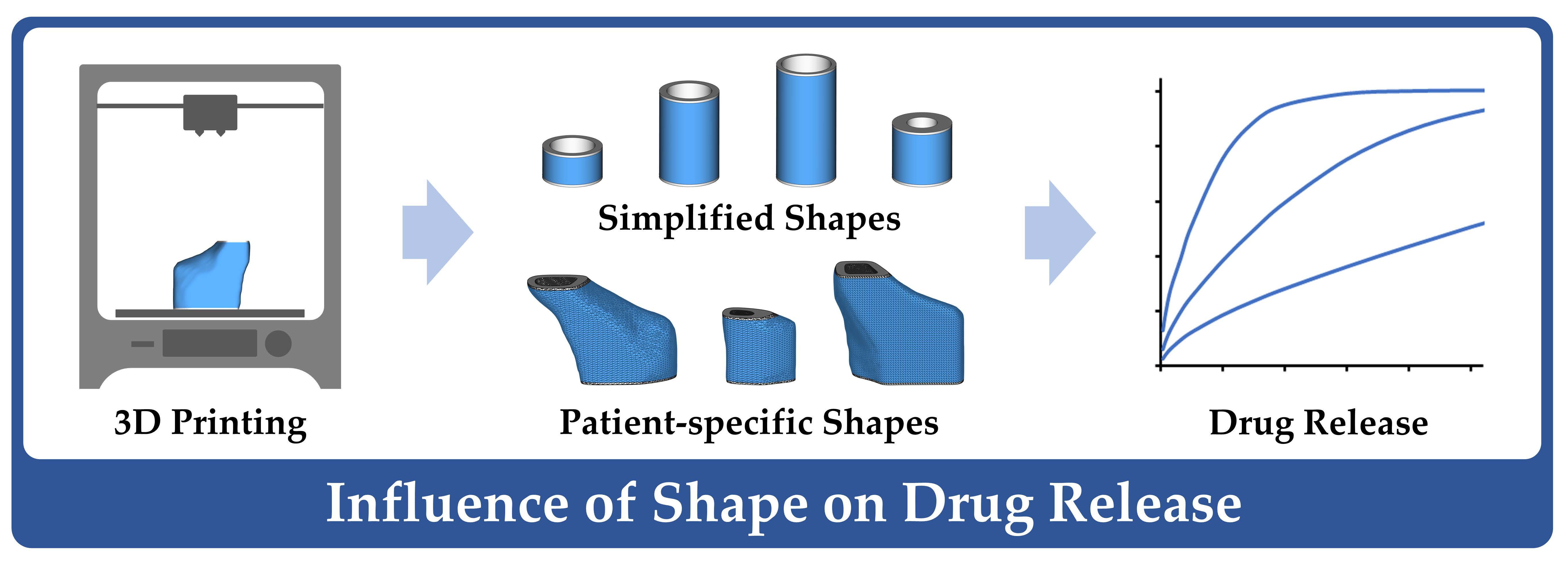
The Influence of Shape Parameters on Unidirectional Drug Release from 3D Printed Implants and Prediction of Release from Implants with Individualized Shapes

 , ,
, ,  , and
, and
Abstract
:
1. Introduction
2. Materials and Methods
2.1. Materials
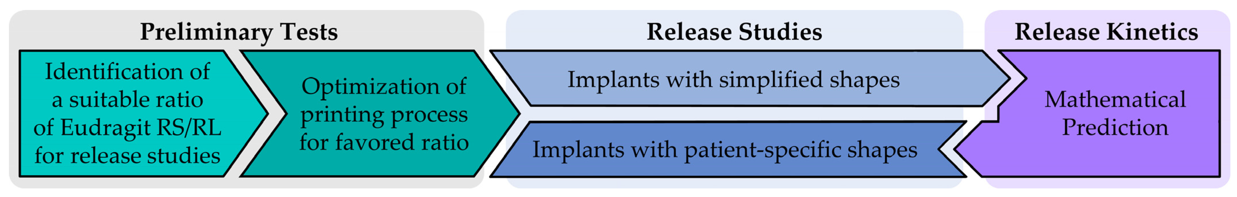
2.2. Workflow
2.3. General Methods
2.3.1. Hot-Melt Extrusion of Drug-Loaded Filaments
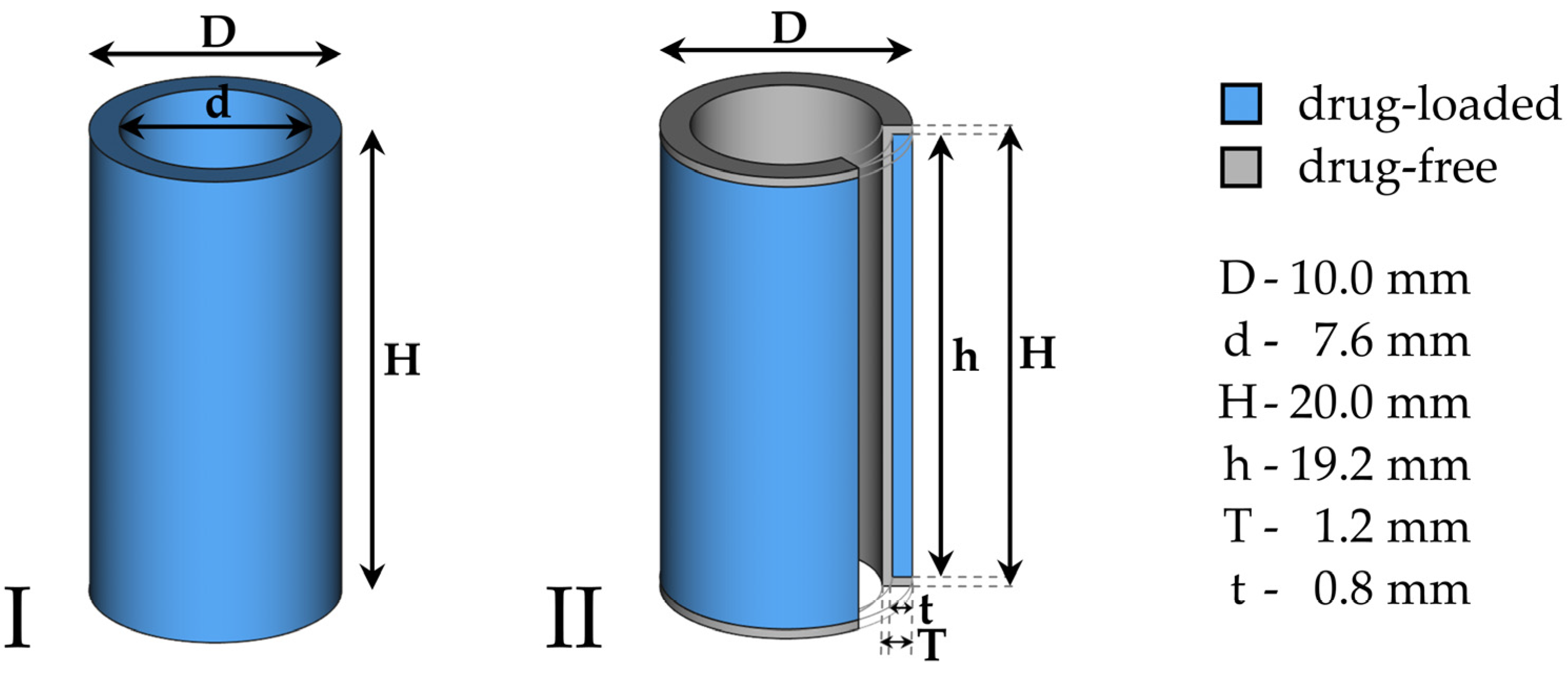
2.3.2. 3D Printing Process and Implant Design
2.3.3. Visual Appearance
2.3.4. Uniformity of Mass, Dimensions, Drug Dose and Content
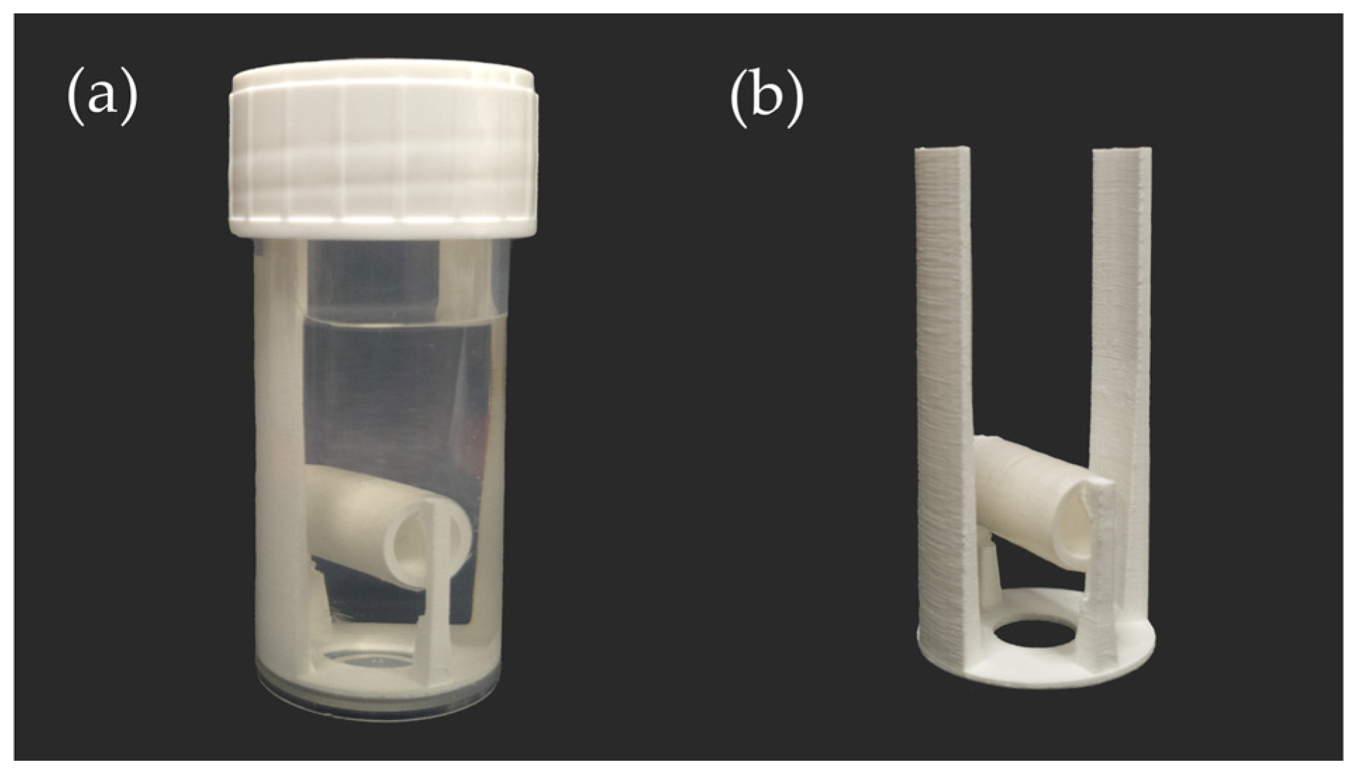
2.3.5. Drug Release Studies
2.4. Preliminary Tests
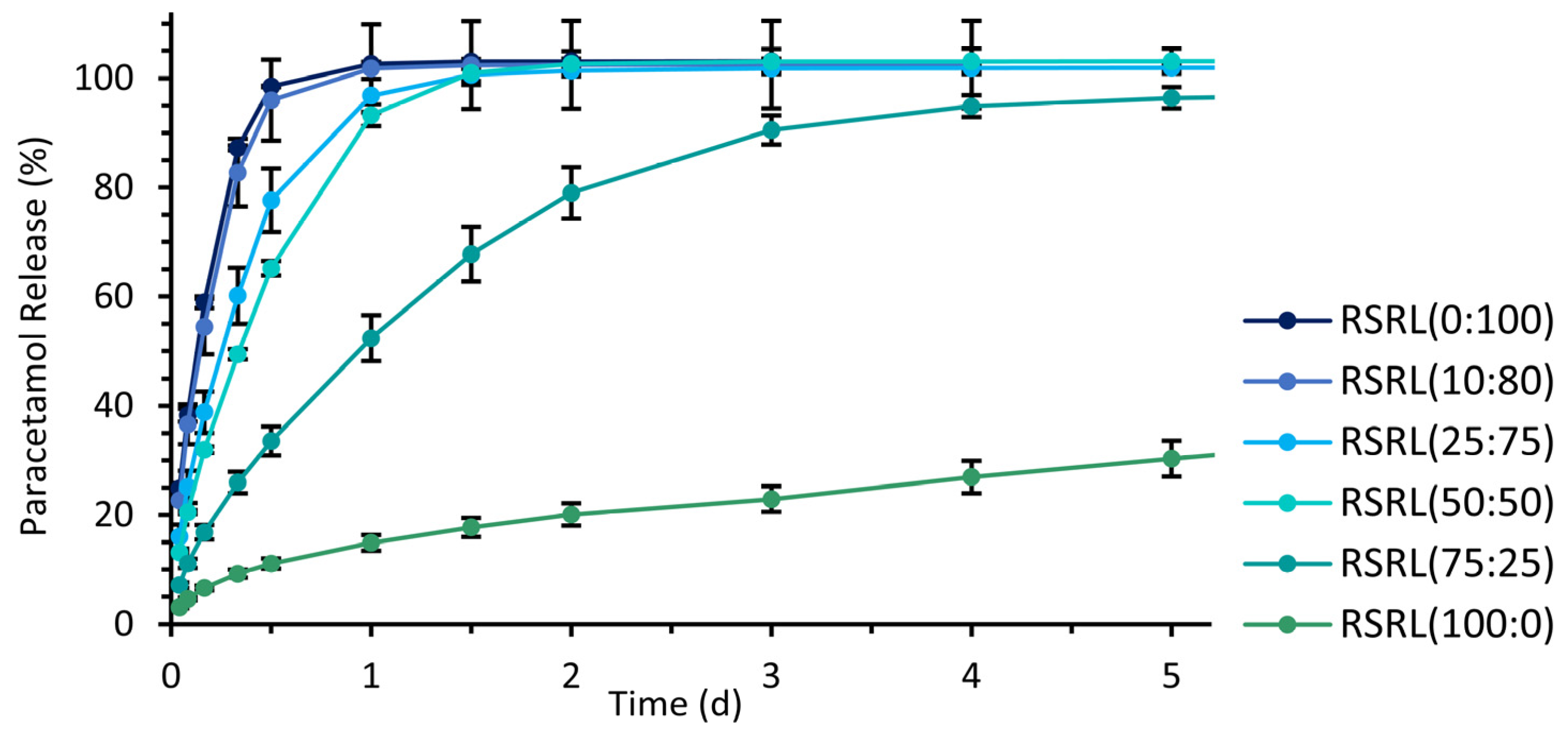
2.4.1. Polymer Ratio of Eudragit® RS and RL
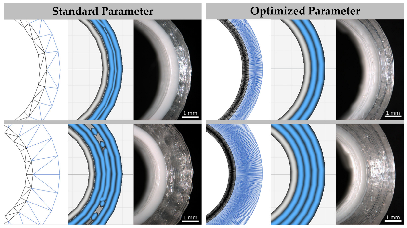
2.4.2. Optimization of Printing Process
2.5. Implants with Simplified Shapes
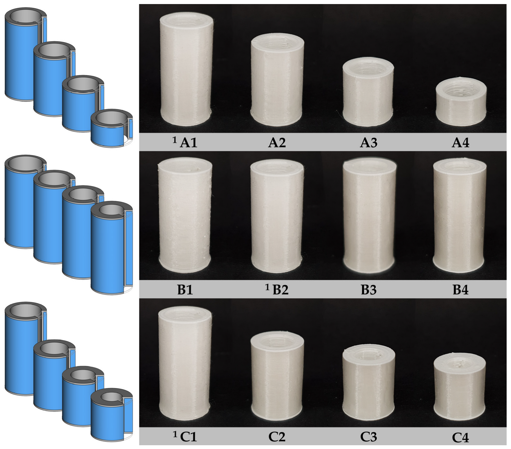
2.5.1. Implant Designs of Simplified Shapes
2.5.2. Estimation of Drug Release Kinetics and Release Prediction
2.6. Implants with Patient-Specific Shapes
2.6.1. Acquisition of Anatomical Shape of Human Frontal Neo-Ostium
2.6.2. Modeling of Patient-Specific Implants
3. Results
3.1. Preliminary Tests
3.1.1. Drug Release from Different Polymer Mixtures
3.1.2. Optimized Printing Process
3.2. Implants with Simplified Shape
3.2.1. Characterization of Implants with Simplified Shape
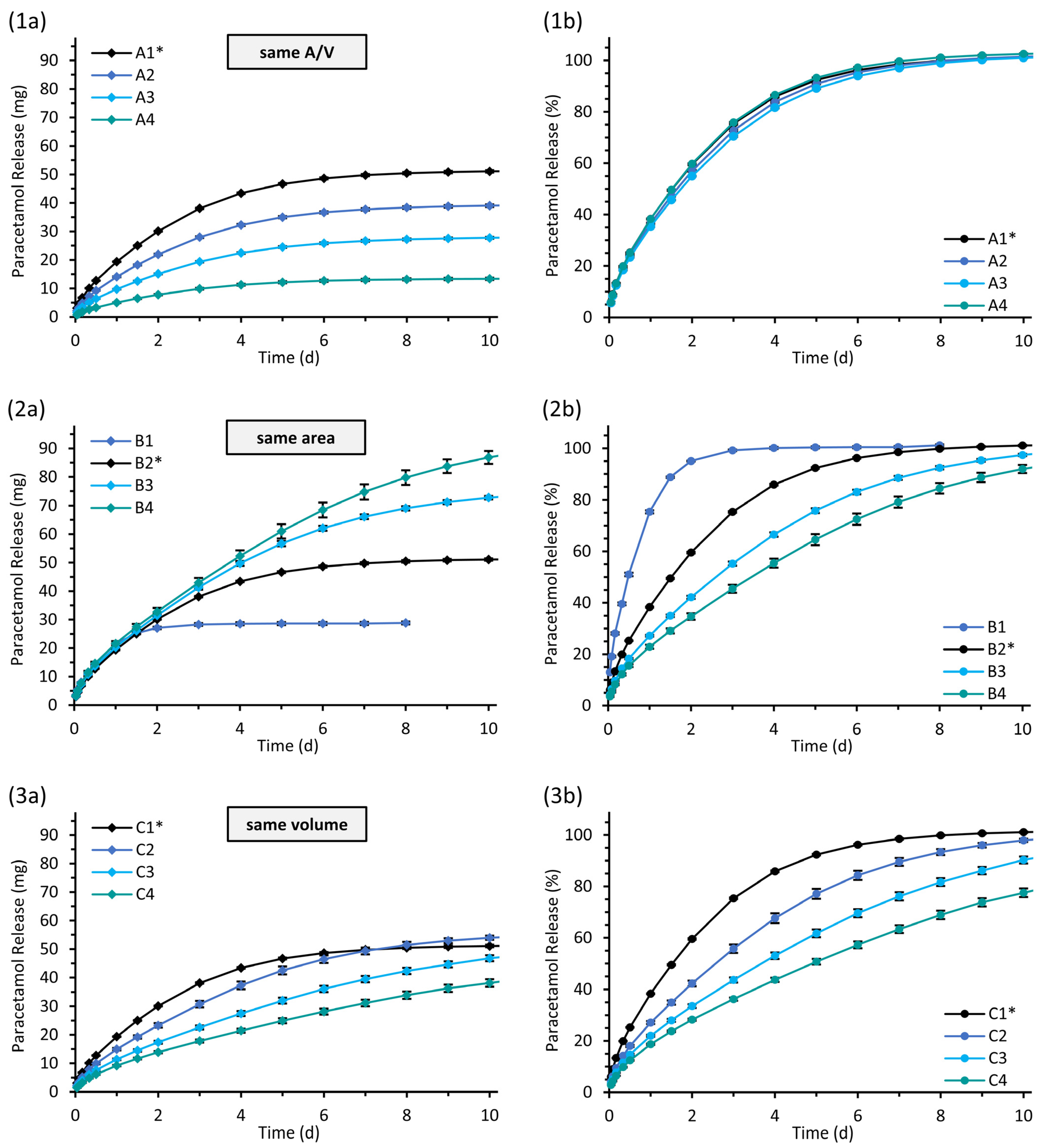
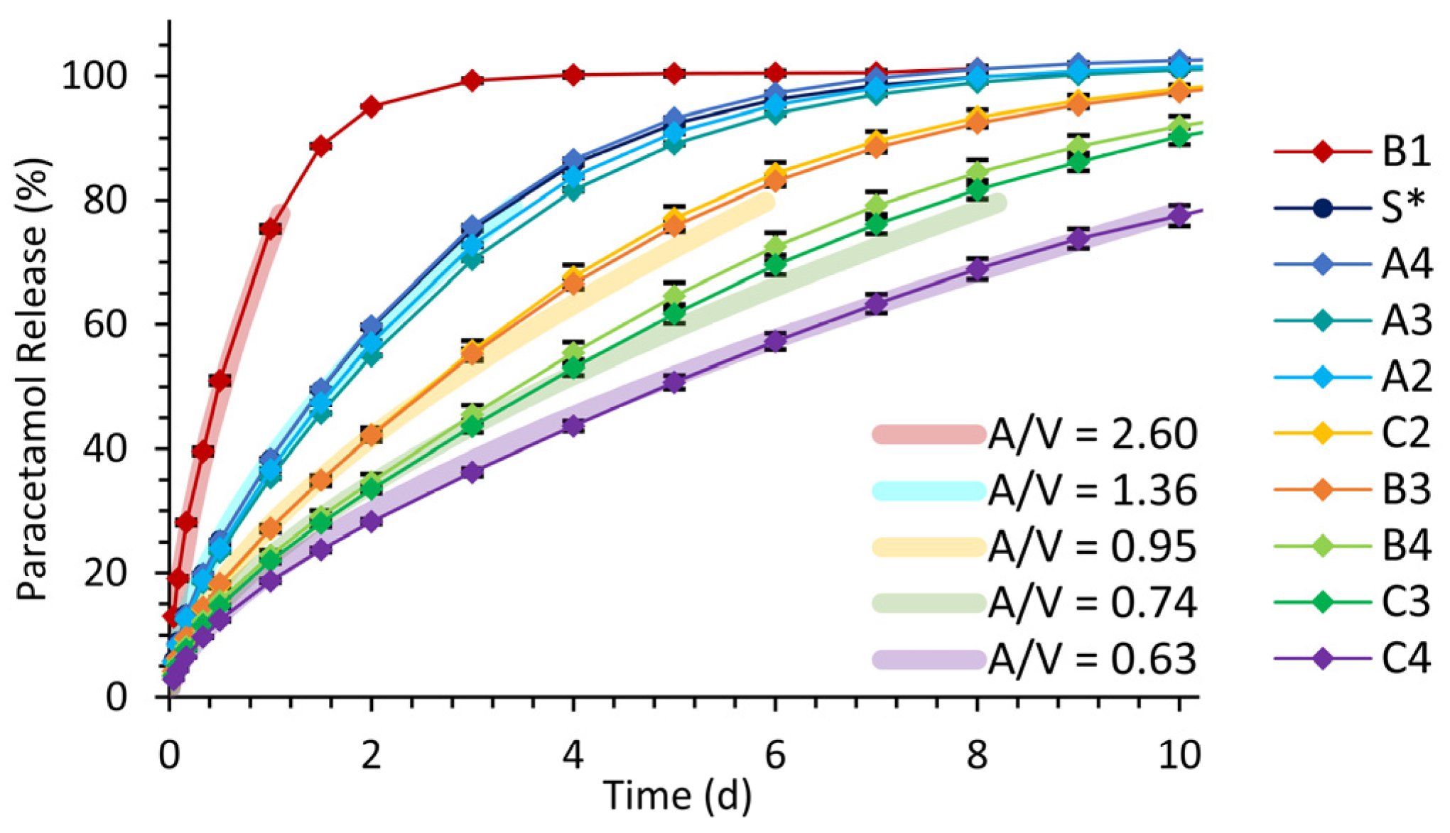
3.2.2. Drug Release from Implants with Simplified Shapes
3.2.3. Drug Release Kinetics and Release Prediction
3.3. Implants with Patient-Specific Shape
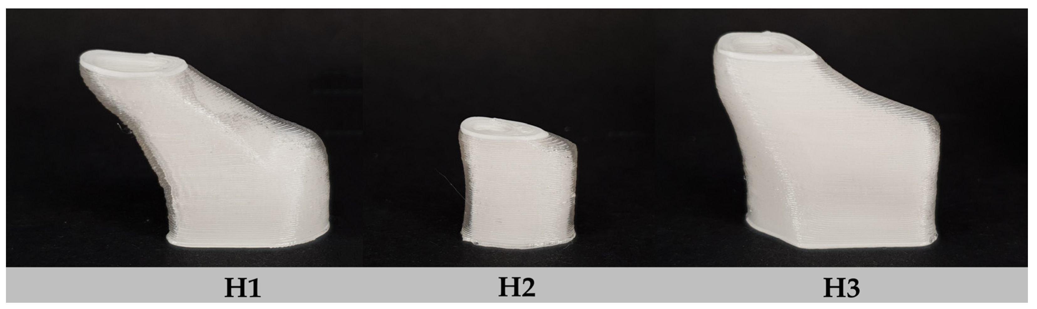
3.3.1. Characterization of Implants with Patient-Specific Shape
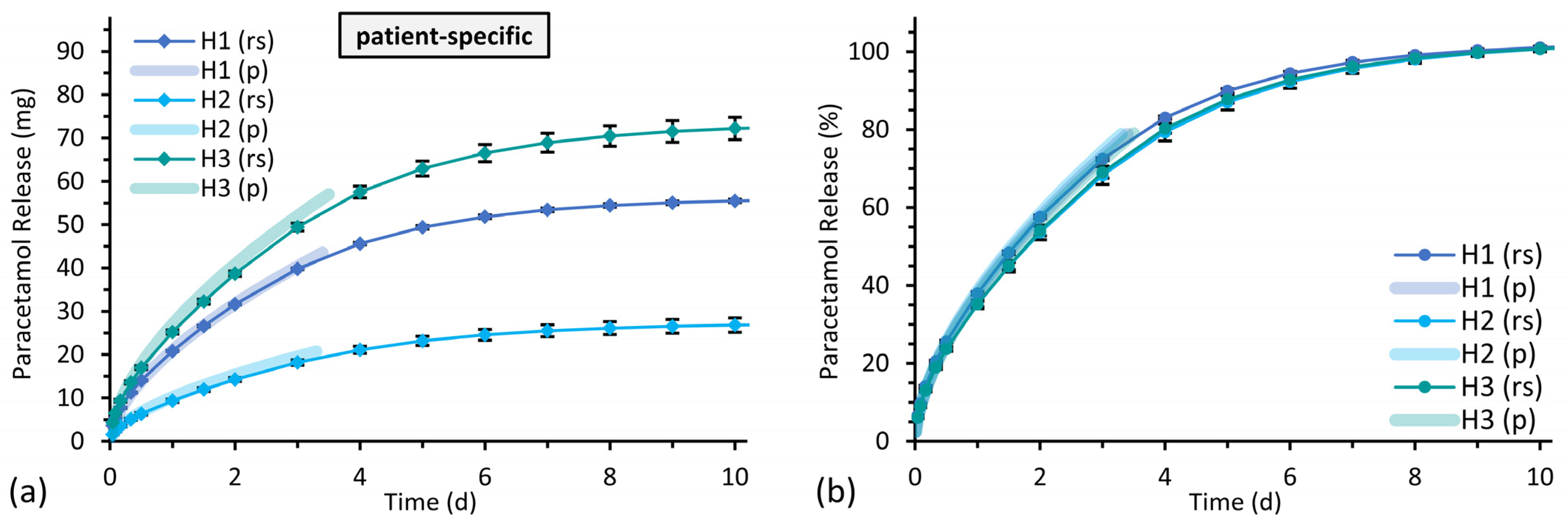
3.3.2. Drug Release from Implants with Patient-Specific Shape
4. Discussion
4.1. Eudragit® RS/RL as Material for 3D Printed Implants
4.2. Optimization of the Printing Process for Homogeneous Implants
4.3. Drug Release Studies
4.4. Drug Release from Implants with Simplified Shapes
4.5. Predictability of Drug Release from Implants with Patient-Specific Shapes
5. Conclusions
Author Contributions
Funding

Institutional Review Board Statement
Informed Consent Statement
Data Availability Statement
Acknowledgments
Conflicts of Interest
References
- Bácskay, I.; Ujhelyi, Z.; Fehér, P.; Arany, P. The Evolution of the 3D-Printed Drug Delivery Systems: A Review. Pharmaceutics 2022, 14, 1312. [Google Scholar] [CrossRef]
- Elkasabgy, N.A.; Mahmoud, A.A.; Maged, A. 3D Printing: An Appealing Route for Customized Drug Delivery Systems. Int. J. Pharm. 2020, 588, 119732. [Google Scholar] [CrossRef] [PubMed]
- El Aita, I.; Ponsar, H.; Quodbach, J. A Critical Review on 3D-Printed Dosage Forms. Curr. Pharm. Des. 2018, 24, 4957–4978. [Google Scholar] [CrossRef]
- Jamróz, W.; Szafraniec, J.; Kurek, M.; Jachowicz, R. 3D Printing in Pharmaceutical and Medical Applications—Recent Achievements and Challenges. Pharm. Res. 2018, 35, 176. [Google Scholar] [CrossRef] [PubMed]
- Zema, L.; Melocchi, A.; Maroni, A.; Gazzaniga, A. Three-Dimensional Printing of Medicinal Products and the Challenge of Personalized Therapy. J. Pharm. Sci. 2017, 106, 1697–1705. [Google Scholar] [CrossRef] [PubMed]
- Melocchi, A.; Uboldi, M.; Maroni, A.; Foppoli, A.; Palugan, L.; Zema, L.; Gazzaniga, A. 3D Printing by Fused Deposition Modeling of Single- and Multi-Compartment Hollow Systems for Oral Delivery—A Review. Int. J. Pharm. 2020, 579, 119155. [Google Scholar] [CrossRef]
- Xu, X.; Zhao, J.; Wang, M.; Wang, L.; Yang, J. 3D Printed Polyvinyl Alcohol Tablets with Multiple Release Profiles. Sci. Rep. 2019, 9, 12487. [Google Scholar] [CrossRef] [PubMed]
- Zhang, J.; Yang, W.; Vo, A.Q.; Feng, X.; Ye, X.; Kim, D.W.; Repka, M.A. Hydroxypropyl Methylcellulose-Based Controlled Release Dosage by Melt Extrusion and 3D Printing: Structure and Drug Release Correlation. Carbohydr. Polym. 2017, 177, 49–57. [Google Scholar] [CrossRef] [PubMed]
- Goyanes, A.; Wang, J.; Buanz, A.; Martínez-Pacheco, R.; Telford, R.; Gaisford, S.; Basit, A.W. 3D Printing of Medicines: Engineering Novel Oral Devices with Unique Design and Drug Release Characteristics. Mol. Pharm. 2015, 12, 4077–4084. [Google Scholar] [CrossRef]
- Sun, Y.; Soh, S. Printing Tablets with Fully Customizable Release Profiles for Personalized Medicine. Adv. Mater. 2015, 27, 7847–7853. [Google Scholar] [CrossRef] [PubMed]
- Domsta, V.; Seidlitz, A. 3D-Printing of Drug-Eluting Implants: An Overview of the Current Developments Described in the Literature. Molecules 2021, 26, 4066. [Google Scholar] [CrossRef]
- Ganguli, A.; Pagan-Diaz, G.J.; Grant, L.; Cvetkovic, C.; Bramlet, M.; Vozenilek, J.; Kesavadas, T.; Bashir, R. 3D Printing for Preoperative Planning and Surgical Training: A Review. Biomed. Microdevices 2018, 20, 65. [Google Scholar] [CrossRef] [PubMed]
- Wong, K.C. 3D-Printed Patient-Specific Applications in Orthopedics. Orthop. Res. Rev. 2016, 8, 57–66. [Google Scholar] [CrossRef]
- Tack, P.; Victor, J.; Gemmel, P.; Annemans, L. 3D-Printing Techniques in a Medical Setting: A Systematic Literature Review. Biomed. Eng. Online 2016, 15, 115. [Google Scholar] [CrossRef] [PubMed]
- Matin-Mann, F.; Gao, Z.; Schwieger, J.; Ulbricht, M.; Domsta, V.; Senekowitsch, S.; Weitschies, W.; Seidlitz, A.; Doll, K.; Stiesch, M.; et al. Individualized, Additively Manufactured Drug-Releasing External Ear Canal Implant for Prevention of Postoperative Restenosis: Development, In Vitro Testing, and Proof of Concept in an Individual Curative Trial. Pharmaceutics 2022, 14, 1242. [Google Scholar] [CrossRef] [PubMed]
- Boyer, C.J.; Woerner, J.E.; Galea, C.; Gatlin, C.A.; Ghali, G.E.; Mills, D.K.; Weisman, J.A.; McGee, D.J.; Alexander, J.S. Personalized Bioactive Nasal Supports for Postoperative Cleft Rhinoplasty. J. Oral Maxillofac. Surg. 2018, 76, 1562.e1–1562.e5. [Google Scholar] [CrossRef] [PubMed]
- Muwaffak, Z.; Goyanes, A.; Clark, V.; Basit, A.W.; Hilton, S.T.; Gaisford, S. Patient-Specific 3D Scanned and 3D Printed Antimicrobial Polycaprolactone Wound Dressings. Int. J. Pharm. 2017, 527, 161–170. [Google Scholar] [CrossRef]
- Thakkar, R.; Pillai, A.R.; Zhang, J.; Zhang, Y.; Kulkarni, V.; Maniruzzaman, M. Novel On-Demand 3-Dimensional (3-D) Printed Tablets Using Fill Density as an Effective Release-Controlling Tool. Polymers 2020, 12, 1872. [Google Scholar] [CrossRef] [PubMed]
- Raju, P.N.; Prakash, K.; Rao, T.R.; Reddy, B.C.S.; Sreenivasulu, V.; Narasu, M.L. Effect of Tablet Surface Area and Surface Area/Volume on Drug Release from Lamivudine Extended Release Matrix Tablets. Int. J. Pharm. Sci. Nanotechnol. 2010, 3, 872–876. [Google Scholar] [CrossRef]
- Reynolds, T.D.; Mitchell, S.A.; Balwinski, K.M. Investigation of the Effect of Tablet Surface Area/Volume on Drug Release from Hydroxypropylmethylcellulose Controlled-Release Matrix Tablets. Drug Dev. Ind. Pharm. 2002, 28, 457–466. [Google Scholar] [CrossRef]
- Karasulu, H.Y.; Ertan, G. Different Geometric Shaped Hydrogel Theophylline Tablets: Statistical Approach for Estimating Drug Release. Il Farm. 2002, 57, 939–945. [Google Scholar] [CrossRef] [PubMed]
- Karasulu, H.Y.; Ertan, G.; Köse, T. Modeling of Theophylline Release from Different Geometrical Erodible Tablets. Eur. J. Pharm. Biopharm. 2000, 49, 177–182. [Google Scholar] [CrossRef]
- Cheng, K.; Zhu, J.; Song, X.; Sun, L.; Zhang, J. Studies of Hydroxypropyl Methylcellulose Donut-Shaped Tablets. Drug Dev. Ind. Pharm. 1999, 25, 1067–1071. [Google Scholar] [CrossRef]
- Windolf, H.; Chamberlain, R.; Quodbach, J. Predicting Drug Release from 3D Printed Oral Medicines Based on the Surface Area to Volume Ratio of Tablet Geometry. Pharmaceutics 2021, 13, 1453. [Google Scholar] [CrossRef]
- Obeid, S.; Madžarević, M.; Krkobabić, M.; Ibrić, S. Predicting Drug Release from Diazepam FDM Printed Tablets Using Deep Learning Approach: Influence of Process Parameters and Tablet Surface/Volume Ratio. Int. J. Pharm. 2021, 601, 120507. [Google Scholar] [CrossRef] [PubMed]
- Gorkem Buyukgoz, G.; Soffer, D.; Defendre, J.; Pizzano, G.M.; Davé, R.N. Exploring Tablet Design Options for Tailoring Drug Release and Dose via Fused Deposition Modeling (FDM) 3D Printing. Int. J. Pharm. 2020, 591, 119987. [Google Scholar] [CrossRef] [PubMed]
- Korte, C.; Quodbach, J. 3D-Printed Network Structures as Controlled-Release Drug Delivery Systems: Dose Adjustment, API Release Analysis and Prediction. AAPS PharmSciTech 2018, 19, 3333–3342. [Google Scholar] [CrossRef]
- Sadia, M.; Arafat, B.; Ahmed, W.; Forbes, R.T.; Alhnan, M.A. Channelled Tablets: An Innovative Approach to Accelerating Drug Release from 3D Printed Tablets. J. Control. Release 2018, 269, 355–363. [Google Scholar] [CrossRef]
- Kyobula, M.; Adedeji, A.; Alexander, M.R.; Saleh, E.; Wildman, R.; Ashcroft, I.; Gellert, P.R.; Roberts, C.J. 3D Inkjet Printing of Tablets Exploiting Bespoke Complex Geometries for Controlled and Tuneable Drug Release. J. Control. Release 2017, 261, 207–215. [Google Scholar] [CrossRef]
- Goyanes, A.; Buanz, A.B.M.; Hatton, G.B.; Gaisford, S.; Basit, A.W. 3D Printing of Modified-Release Aminosalicylate (4-ASA and 5-ASA) Tablets. Eur. J. Pharm. Biopharm. 2015, 89, 157–162. [Google Scholar] [CrossRef]
- Martinez, P.R.; Goyanes, A.; Basit, A.W.; Gaisford, S. Influence of Geometry on the Drug Release Profiles of Stereolithographic (SLA) 3D-Printed Tablets. AAPS PharmSciTech 2018, 19, 3355–3361. [Google Scholar] [CrossRef] [PubMed]
- Gao, Z.; Matin, F.; Weber, C.; John, S.; Lenarz, T.; Scheper, V. High Variability of Postsurgical Anatomy Supports the Need for Individualized Drug-Eluting Implants to Treat Chronic Rhinosinusitis. Life 2020, 10, 353. [Google Scholar] [CrossRef]
- Parikh, A.; Anand, U.; Ugwu, M.; Feridooni, T.; Massoud, E.; Agu, R. Drug-Eluting Nasal Implants: Formulation, Characterization, Clinical Applications and Challenges. Pharmaceutics 2014, 6, 249–267. [Google Scholar] [CrossRef] [PubMed]
- Campbell, R.G.; Kennedy, D.W. What Is New and Promising with Drug-Eluting Stents in Sinus Surgery? Curr. Opin. Otolaryngol. Head Neck Surg. 2014, 22, 2–7. [Google Scholar] [CrossRef]
- Kennedy, D.W. The PROPELTM Steroid-Releasing Bioabsorbable Implant to Improve Outcomes of Sinus Surgery. Expert Rev. Respir. Med. 2012, 6, 493–498. [Google Scholar] [CrossRef]
- Murr, A.H.; Smith, T.L.; Hwang, P.H.; Bhattacharyya, N.; Lanier, B.J.; Stambaugh, J.W.; Mugglin, A.S. Safety and Efficacy of a Novel Bioabsorbable, Steroid-Eluting Sinus Stent. Int. Forum Allergy Rhinol. 2011, 1, 23–32. [Google Scholar] [CrossRef]
- Catalano, P.J.; Thong, M.; Weiss, R.; Rimash, T. The MicroFlow Spacer: A Drug-Eluting Stent for the Ethmoid Sinus. Indian J. Otolaryngol. Head Neck Surg. 2011, 63, 279–284. [Google Scholar] [CrossRef]
- Catalano, P.J.; Thong, M.; Garg, V. The MicroFlow Spacer: A Drug-Eluting Stent for the Ethmoid Sinus. Oper. Technol. Otolaryngol. Neck Surg. 2009, 20, 108–113. [Google Scholar] [CrossRef]
- Sharma, S.; Sharma, J.B.; Bhatt, S.; Kumar, M. Method Development and Validation of UV Spectrophotometric Method for the Quantitative Estimation of Curcumin in Simulated Nasal Fluid. Drug Res. 2020, 70, 356–359. [Google Scholar] [CrossRef] [PubMed]
- Ibrahim, H.K.; Abdel Malak, N.S.; Abdel Halim, S.A. Formulation of Convenient, Easily Scalable, and Efficient Granisetron HCl Intranasal Droppable Gels. Mol. Pharm. 2015, 12, 2019–2025. [Google Scholar] [CrossRef]
- Pagar, S.A.; Shinkar, D.M.; Saudagar, R.B. Development and Evaluation of in Situ Nasal Mucoadhesive Gel of Metoprolol Succinate by Using 32 Full Factorial Design. Int. J. Pharm. Pharm. Sci. 2014, 6, 218–223. [Google Scholar]
- Farid, R.M.; Etman, M.A.; Nada, A.H.; Ebian, A.E.A.R. Formulation and In Vitro Evaluation of Salbutamol Sulphate In Situ Gelling Nasal Inserts. AAPS PharmSciTech 2013, 14, 712–718. [Google Scholar] [CrossRef]
- Saindane, N.S.; Pagar, K.P.; Vavia, P.R. Nanosuspension Based In Situ Gelling Nasal Spray of Carvedilol: Development, In Vitro and In Vivo Characterization. AAPS PharmSciTech 2013, 14, 189–199. [Google Scholar] [CrossRef] [PubMed]
- Zaki, N.M.; Awad, G.A.; Mortada, N.D.; Abd ElHady, S.S. Enhanced Bioavailability of Metoclopramide HCl by Intranasal Administration of a Mucoadhesive in Situ Gel with Modulated Rheological and Mucociliary Transport Properties. Eur. J. Pharm. Sci. 2007, 32, 296–307. [Google Scholar] [CrossRef] [PubMed]
- Callens, C.; Ceulemans, J.; Ludwig, A.; Foreman, P.; Remon, J.P. Rheological Study on Mucoadhesivity of Some Nasal Powder Formulations. Eur. J. Pharm. Biopharm. 2003, 55, 323–328. [Google Scholar] [CrossRef]
- Paarakh, M.P.; Jose, P.A.; Setty, C.; Christoper, G.V.P. Release Kinetics–Concepts and Applications. Int. J. Pharm. Res. Technol. 2018, 8, 12–20. [Google Scholar] [CrossRef]
- Dash, S.; Murthy, P.N.; Nath, L.; Chowdhury, P. Kinetic Modeling on Drug Release from Controlled Drug Delivery Systems. Acta Pol. Pharm. 2010, 67, 217–223. [Google Scholar] [PubMed]
- Costa, P.; Sousa Lobo, J.M. Modeling and Comparison of Dissolution Profiles. Eur. J. Pharm. Sci. 2001, 13, 123–133. [Google Scholar] [CrossRef]
- Higuchi, T. Rate of Release of Medicaments from Ointment Bases Containing Drugs in Suspension. J. Pharm. Sci. 1961, 50, 874–875. [Google Scholar] [CrossRef]
- Higuchi, T. Mechanism of Sustained-action Medication. Theoretical Analysis of Rate of Release of Solid Drugs Dispersed in Solid Matrices. J. Pharm. Sci. 1963, 52, 1145–1149. [Google Scholar] [CrossRef]
- Weibull, W. A Statistical Distribution Function of Wide Applicability. J. Appl. Mech. 1951, 18, 293–297. [Google Scholar] [CrossRef]
- Langenbucher, F. Linearization of Dissolution Rate Curves by the Weibull Distribution. J. Pharm. Pharmacol. 1972, 24, 979–981. [Google Scholar] [CrossRef] [PubMed]
- Korsmeyer, R.W.; Gurny, R.; Doelker, E.; Buri, P.; Peppas, N.A. Mechanisms of Solute Release from Porous Hydrophilic Polymers. Int. J. Pharm. 1983, 15, 25–35. [Google Scholar] [CrossRef]
- Ritger, P.L.; Peppas, N.A. A Simple Equation for Description of Solute Release I. Fickian and Non-Fickian Release from Non-Swellable Devices in the Form of Slabs, Spheres, Cylinders or Discs. J. Control. Release 1987, 5, 23–36. [Google Scholar] [CrossRef]
- FDA. Guidance for Industry-Dissolution Testing of Immediate Release Solid Oral Dosage Forms; FDA Center for Drug Evaluation and Research (CDER): Silver Spring, MD, USA, 1997. [Google Scholar]
- Diaz, D.A.; Colgan, S.T.; Langer, C.S.; Bandi, N.T.; Likar, M.D.; Van Alstine, L. Dissolution Similarity Requirements: How Similar or Dissimilar Are the Global Regulatory Expectations? AAPS J. 2016, 18, 15–22. [Google Scholar] [CrossRef]
- dos Santos, J.; da Silva, G.S.; Velho, M.C.; Beck, R.C.R. Eudragit®: A Versatile Family of Polymers for Hot Melt Extrusion and 3D Printing Processes in Pharmaceutics. Pharmaceutics 2021, 13, 1424. [Google Scholar] [CrossRef]
- Jain, S.K.; Jain, A.K.; Rajpoot, K. Expedition of Eudragit® Polymers in the Development of Novel Drug Delivery Systems. Curr. Drug Deliv. 2020, 17, 448–469. [Google Scholar] [CrossRef]
- Thakral, S.; Thakral, N.K.; Majumdar, D.K. Eudragit®: A Technology Evaluation. Expert Opin. Drug Deliv. 2013, 10, 131–149. [Google Scholar] [CrossRef]
- Kempin, W.; Franz, C.; Koster, L.-C.; Schneider, F.; Bogdahn, M.; Weitschies, W.; Seidlitz, A. Assessment of Different Polymers and Drug Loads for Fused Deposition Modeling of Drug Loaded Implants. Eur. J. Pharm. Biopharm. 2017, 115, 84–93. [Google Scholar] [CrossRef]
- Kuźmińska, M.; Pereira, B.C.; Habashy, R.; Peak, M.; Isreb, M.; Gough, T.D.; Isreb, A.; Alhnan, M.A. Solvent-Free Temperature-Facilitated Direct Extrusion 3D Printing for Pharmaceuticals. Int. J. Pharm. 2021, 598, 120305. [Google Scholar] [CrossRef]
- Park, J.-B.; Lee, B.-J.; Kang, C.-Y.; Repka, M.A. Process Analytical Quality Control of Tailored Drug Release Formulation Prepared via Hot-Melt Extrusion Technology. J. Drug Deliv. Sci. Technol. 2017, 38, 51–58. [Google Scholar] [CrossRef] [PubMed]
- Evonik Operations GmbH Technical Information: EUDRAGIT® RL and EUDRAGIT® RS-Summary of the Safety Data. Available online: https://oncare.evonik.com/download_area/ (accessed on 23 January 2023).
- Kaval, B.; Kapkın, E.; Kaynak, M.S. Release Kinetics of 3D Printed Oral Solid Dosage Forms: An Overview. Eur. J. Life Sci. 2022, 1, 70–88. [Google Scholar] [CrossRef]
- Auriemma, G.; Tommasino, C.; Falcone, G.; Esposito, T.; Sardo, C.; Aquino, R.P. Additive Manufacturing Strategies for Personalized Drug Delivery Systems and Medical Devices: Fused Filament Fabrication and Semi Solid Extrusion. Molecules 2022, 27, 2784. [Google Scholar] [CrossRef] [PubMed]
- Silva, I.A.; Lima, A.L.; Gratieri, T.; Gelfuso, G.M.; Sa-Barreto, L.L.; Cunha-Filho, M. Compatibility and Stability Studies Involving Polymers Used in Fused Deposition Modeling 3D Printing of Medicines. J. Pharm. Anal. 2022, 12, 424–435. [Google Scholar] [CrossRef]
- Jendrzejewska, I.; Goryczka, T.; Pietrasik, E.; Klimontko, J.; Jampilek, J. X-ray and Thermal Analysis of Selected Drugs Containing Acetaminophen. Molecules 2020, 25, 5909. [Google Scholar] [CrossRef]
- Tiffour, I.; Dehbi, A.; Mourad, A.-H.I.; Belfedal, A. Synthesis and Characterization of a New Organic Semiconductor Material. Mater. Chem. Phys. 2016, 178, 49–56. [Google Scholar] [CrossRef]
- Hiendrawan, S.; Veriansyah, B.; Widjojokusumo, E.; Soewandhi, S.N.; Wikarsa, S.; Tjandrawinata, R.R. Simultaneous Cocrystallization and Micronization of Paracetamol-Dipicolinic Acid Cocrystal by Supercritical Antisolvent (SAS). Int. J. Pharm. Pharm. Sci. 2016, 8, 89–98. [Google Scholar]
- Yang, M.; Wang, P.; Huang, C.-Y.; Ku, M.S.; Liu, H.; Gogos, C. Solid Dispersion of Acetaminophen and Poly(Ethylene Oxide) Prepared by Hot-Melt Mixing. Int. J. Pharm. 2010, 395, 53–61. [Google Scholar] [CrossRef] [PubMed]
- Crowley, M.M.; Zhang, F.; Repka, M.A.; Thumma, S.; Upadhye, S.B.; Kumar Battu, S.; McGinity, J.W.; Martin, C. Pharmaceutical Applications of Hot-Melt Extrusion: Part I. Drug Dev. Ind. Pharm. 2007, 33, 909–926. [Google Scholar] [CrossRef]
- Siepmann, F.; Le Brun, V.; Siepmann, J. Drugs Acting as Plasticizers in Polymeric Systems: A Quantitative Treatment. J. Control. Release 2006, 115, 298–306. [Google Scholar] [CrossRef]
- Farmer, Z.-L.; Utomo, E.; Domínguez-Robles, J.; Mancinelli, C.; Mathew, E.; Larrañeta, E.; Lamprou, D.A. 3D Printed Estradiol-Eluting Urogynecological Mesh Implants: Influence of Material and Mesh Geometry on Their Mechanical Properties. Int. J. Pharm. 2021, 593, 120145. [Google Scholar] [CrossRef]
- Domínguez-Robles, J.; Mancinelli, C.; Mancuso, E.; García-Romero, I.; Gilmore, B.F.; Casettari, L.; Larrañeta, E.; Lamprou, D.A. 3D Printing of Drug-Loaded Thermoplastic Polyurethane Meshes: A Potential Material for Soft Tissue Reinforcement in Vaginal Surgery. Pharmaceutics 2020, 12, 63. [Google Scholar] [CrossRef] [PubMed]
- Mathew, E.; Domínguez-Robles, J.; Larrañeta, E.; Lamprou, D.A. Fused Deposition Modelling as a Potential Tool for Antimicrobial Dialysis Catheters Manufacturing: New Trends vs. Conventional Approaches. Coatings 2019, 9, 515. [Google Scholar] [CrossRef]
- Genina, N.; Holländer, J.; Jukarainen, H.; Mäkilä, E.; Salonen, J.; Sandler, N. Ethylene Vinyl Acetate (EVA) as a New Drug Carrier for 3D Printed Medical Drug Delivery Devices. Eur. J. Pharm. Sci. 2016, 90, 53–63. [Google Scholar] [CrossRef] [PubMed]
- Kempin, W.; Domsta, V.; Grathoff, G.; Brecht, I.; Semmling, B.; Tillmann, S.; Weitschies, W.; Seidlitz, A. Immediate Release 3D-Printed Tablets Produced Via Fused Deposition Modeling of a Thermo-Sensitive Drug. Pharm. Res. 2018, 35, 124. [Google Scholar] [CrossRef] [PubMed]
- Ponsar, H.; Wiedey, R.; Quodbach, J. Hot-Melt Extrusion Process Fluctuations and Their Impact on Critical Quality Attributes of Filaments and 3D-Printed Dosage Forms. Pharmaceutics 2020, 12, 511. [Google Scholar] [CrossRef]
- Jayashuriya, M.; Gautam, S.; Aravinth, A.N.; Vasanth, G.; Murugan, R. Studies on the Effect of Part Geometry and Process Parameter on the Dimensional Deviation of Additive Manufactured Part Using ABS Material. Prog. Addit. Manuf. 2022, 7, 1183–1193. [Google Scholar] [CrossRef]
- Taşdemir, V. Investigation of Dimensional Integrity and Surface Quality of Different Thin-Walled Geometric Parts Produced via Fused Deposition Modeling 3D Printing. J. Mater. Eng. Perform. 2021, 30, 3381–3387. [Google Scholar] [CrossRef]
- Păcurar, R.; Buzilă, V.; Păcurar, A.; Guţiu, E.; Dan Stan, S.; Berce, P. Research on Improving the Accuracy of FDM 3D Printing Process by Using a New Designed Calibrating Part. MATEC Web Conf. 2019, 299, 01007. [Google Scholar] [CrossRef]
- Yaman, U. Shrinkage Compensation of Holes via Shrinkage of Interior Structure in FDM Process. Int. J. Adv. Manuf. Technol. 2018, 94, 2187–2197. [Google Scholar] [CrossRef]
- Gray, V.; Cady, S.; Curran, D.; DeMuth, J.; Eradiri, O.; Hussain, M.; Krämer, J.; Shabushnig, J.; Stippler, E. In Vitro Release Test Methods for Drug Formulations for Parenteral Applications. Dissolution Technol. 2018, 25, 8–13. [Google Scholar] [CrossRef]
- Kastellorizios, M.; Burgess, D.J. In Vitro Drug Release Testing and In Vivo/In Vitro Correlation for Long Acting Implants and Injections. In Long Acting Injections and Implants; Springer: Boston, MA, USA, 2012; pp. 475–503. ISBN 9781461405542. [Google Scholar]
- Siewert, M.; Dressman, J.; Brown, C.; Shah, V. FIP/AAPS Guidelines for Dissolution/In Vitro Release Testing of Novel/Special Dosage Forms. Dissolution Technol. 2003, 10, 6–15. [Google Scholar] [CrossRef]
- Messerklinger, W. On the Drainage of the Normal Frontal Sinus of Man. Acta Oto-Laryngol. 1967, 63, 176–181. [Google Scholar] [CrossRef] [PubMed]
- Burke, W. The Ionic Composition of Nasal Fluid and Its Function. Health 2014, 6, 720–728. [Google Scholar] [CrossRef]
- Kim, B.G.; Kim, J.H.; Kim, S.W.; Kim, S.W.; Jin, K.S.; Cho, J.H.; Kang, J.M.; Park, S.Y. Nasal PH in Patients with Chronic Rhinosinusitis before and after Endoscopic Sinus Surgery. Am. J. Otolaryngol.-Head Neck Med. Surg. 2013, 34, 505–507. [Google Scholar] [CrossRef]
- Washington, N.; Steele, R.J.C.; Jackson, S.J.; Bush, D.; Mason, J.; Gill, D.A.; Pitt, K.; Rawlins, D.A. Determination of Baseline Human Nasal PH and the Effect of Intranasally Administered Buffers. Int. J. Pharm. 2000, 198, 139–146. [Google Scholar] [CrossRef]
- England, R.J.A.; Homer, J.J.; Knight, L.C.; Ell, S.R. Nasal PH Measurement: A Reliable and Repeatable Parameter. Clin. Otolaryngol. 1999, 24, 67–68. [Google Scholar] [CrossRef]
- Zippel, R.; Ebel, R. Vergleichende PH-Messungen an Schleimhäuten der Nase und des Mundrachens Bei Gesunden und Laryngektomierten. Arch. Klin. Exp. Ohren. Nasen. Kehlkopfheilkd. 1972, 201, 49–56. [Google Scholar] [CrossRef]
- Lindemann, J.; Leiacker, R.; Rettinger, G.; Keck, T. Nasal Mucosal Temperature during Respiration. Clin. Otolaryngol. 2002, 27, 135–139. [Google Scholar] [CrossRef]
- Keck, T.; Leiacker, R.; Riechelmann, H.; Rettinger, G. Temperature Profile in the Nasal Cavity. Laryngoscope 2000, 110, 651–654. [Google Scholar] [CrossRef]
- Gizurarson, S. The Effect of Cilia and the Mucociliary Clearance on Successful Drug Delivery. Biol. Pharm. Bull. 2015, 38, 497–506. [Google Scholar] [CrossRef] [PubMed]
- Jones, N. The Nose and Paranasal Sinuses Physiology and Anatomy. Adv. Drug Deliv. Rev. 2001, 51, 5–19. [Google Scholar] [CrossRef]
- Marttin, E.; Schipper, N.G.M.; Verhoef, J.C.; Merkus, F.W.H.M. Nasal Mucociliary Clearance as a Factor in Nasal Drug Delivery. Adv. Drug Deliv. Rev. 1998, 29, 13–38. [Google Scholar] [CrossRef]
- Iyer, S.; Barr, W.H.; Karnes, H.T. A ‘Biorelevant’ Approach to Accelerated in Vitro Drug Release Testing of a Biodegradable, Naltrexone Implant. Int. J. Pharm. 2007, 340, 119–125. [Google Scholar] [CrossRef]
- D’Souza, S.S.; Faraj, J.A.; DeLuca, P.P. A Model-Dependent Approach to Correlate Accelerated with Real-Time Release from Biodegradable Microspheres. AAPS PharmSciTech 2005, 6, E553–E564. [Google Scholar] [CrossRef] [PubMed]
- Shameem, M.; Lee, H.; DeLuca, P.P. A Short-Term (Accelerated Release) Approach to Evaluate Peptide Release from PLGA Depot Formulations. AAPS PharmSci 1999, 1, 7. [Google Scholar] [CrossRef] [PubMed]
- Goyanes, A.; Robles Martinez, P.; Buanz, A.; Basit, A.W.; Gaisford, S. Effect of Geometry on Drug Release from 3D Printed Tablets. Int. J. Pharm. 2015, 494, 657–663. [Google Scholar] [CrossRef] [PubMed]
- Glaessl, B.; Siepmann, F.; Tucker, I.; Rades, T.; Siepmann, J. Mathematical Modeling of Drug Release from Eudragit RS-Based Delivery Systems. J. Drug Deliv. Sci. Technol. 2010, 20, 127–133. [Google Scholar] [CrossRef]
- Glaessl, B.; Siepmann, F.; Tucker, I.; Rades, T.; Siepmann, J. Deeper Insight into the Drug Release Mechanisms in Eudragit RL-Based Delivery Systems. Int. J. Pharm. 2010, 389, 139–146. [Google Scholar] [CrossRef] [PubMed]
- Ayyoubi, S.; Cerda, J.R.; Fernández-García, R.; Knief, P.; Lalatsa, A.; Healy, A.M.; Serrano, D.R. 3D Printed Spherical Mini-Tablets: Geometry versus Composition Effects in Controlling Dissolution from Personalised Solid Dosage Forms. Int. J. Pharm. 2021, 597, 120336. [Google Scholar] [CrossRef]
- Manini, G.; Benali, S.; Raquez, J.-M.; Goole, J. Proof of Concept of a Predictive Model of Drug Release from Long-Acting Implants Obtained by Fused-Deposition Modeling. Int. J. Pharm. 2022, 618, 121663. [Google Scholar] [CrossRef] [PubMed]


| Batch Name | Eudragit® RS (% w/w) | Eudragit® RL (% w/w) | TEC (% w/w) | Paracetamol (% w/w) | Eudragit® RS:RL Ratio | Plasticizer: Polymer Ratio |
|---|---|---|---|---|---|---|
| RSRL(0:100) | 0 | 90 | - | 10 | 0:100 | - |
| RSRL(10:80) | 10 | 80 | - | 10 | 10:80 | - |
| RSRL(25:75) | 22.5 | 67.5 | - | 10 | 25:75 | - |
| RSRL(50:50) | 45 | 45 | - | 10 | 50:50 | - |
| RSRL(75:25) | 67.5 | 22.5 | - | 10 | 75:25 | - |
| RSRL(100:0) | 90 | 0 | - | 10 | 100:0 | - |
| RSRL(80:20)_2T | 70.56 | 17.64 | 1.8 | 10 | 80:20 | 2:98 |
| 1 RSRL(80:20)_5T | 68.4 | 17.1 | 4.5 | 10 | 80:20 | 5:95 |
| RSRL(80:20)_10T | 64.8 | 16.2 | 9 | 10 | 80:20 | 10:90 |
| Batch Name | Extruder Temperature (°C) | Screw Speed (rpm) | Feeding Rate (%) | Printing Temperature (°C) | ||
|---|---|---|---|---|---|---|
| Zone 1 | Zone 2 | Zone 3–4 | ||||
| RSRL(0:100) | 120 | 130 | 140 | 15 | 1.5 | 155 |
| RSRL(10:80) | 110 | 140 | 150 | 30 | 2.0 | 155 |
| RSRL(25:75) | 100 | 120 | 140 | 20 | 1.8 | 155 |
| RSRL(50:50) | 100 | 120 | 130 | 20 | 1.8 | 155 |
| RSRL(75:25) | 90 | 105 | 115 | 20 | 1.7 | 155 |
| RSRL(100:0) | 90 | 110 | 115 | 20 | 1.7 | 155 |
| RSRL(80:20)_2T | 110 | 120 | 140 | 20 | 1.8 | 140 |
| 1 RSRL(80:20)_5T | 80 | 110–115 | 115–120 | 20 | 2.7 | 150 |
| RSRL(80:20)_10T | 75 | 90 | 90 | 5 | 0.9 | 2 - |
| Printing Parameter | RSRL(80:20)_5T | PLA |
|---|---|---|
| Printing Temperature (°C) | 150 | 200 |
| Print Speed (mm/s) | 15 | 20–30 |
| Layer Height (mm) | 0.1 | 0.1 |
| Initial Layer Height (mm) | - | 0.3 |
| Skin Overlap Percentage (%) | 0 | 0 |
| Line Width (mm) | 0.4 | 0.4 |
| Extrusion Factor “Flow” (%) | 110 | 110 |
| Outer Wall Line Width (mm) | 0.385 | 0.385 |
| Extrusion Factor “Outer Wall Flow” (%) | 114 | 114 |
| Build Plate Temperature (°C) | 60 | 60 |
| Build Plate Adhesion Type | Skirt | Skirt |
| Build Plate Adhesion | - | Blue Tape |
| Z Seam Position (Simplified Shape) | Sharpest Corner | Sharpest Corner |
| Z Seam Position (Patient-Specific Shape) | 1 Right | 1 Right |
| Design | Height (mm) | Wall Thickness (mm) | Outer Diameter (mm) | Calculated Area (mm²) | Calculated Volume (mm³) | Area/Volume Ratio (mm−1) |
|---|---|---|---|---|---|---|
| 1 A 1 | 19.2 | 0.8 | 10 | 603.19 | 443.94 | 1.36 |
| A 2 | 14.4 | 0.8 | 10 | 452.39 | 332.96 | 1.36 |
| A 3 | 9.6 | 0.8 | 10 | 301.59 | 221.97 | 1.36 |
| A 4 | 4.8 | 0.8 | 10 | 150.80 | 110.99 | 1.36 |
| B 1 | 19.2 | 0.4 | 10 | 603.19 | 231.62 | 2.60 |
| 1 B 2 | 19.2 | 0.8 | 10 | 603.19 | 443.94 | 1.36 |
| B 3 | 19.2 | 1.2 | 10 | 603.19 | 636.96 | 0.95 |
| B 4 | 19.2 | 1.6 | 10 | 603.19 | 810.68 | 0.74 |
| 1 C 1 | 19.2 | 0.8 | 10 | 603.19 | 443.94 | 1.36 |
| C 2 | 13.4 | 1.2 | 10 | 420.97 | 444.55 | 0.95 |
| C 3 | 10.5 | 1.6 | 10 | 329.87 | 443.34 | 0.74 |
| C 4 | 8.8 | 2.0 | 10 | 276.46 | 442.34 | 0.63 |
| Kinetic Model | Kinetic Equation | Linearization Plot | ||
|---|---|---|---|---|
| Zero Order | %Qt | ↔ | t | |
| First Order | ln(100 − %Qt) | ↔ | t | |
| Higuchi [46,49,50] | %Qt | ↔ | ||
| Weibull [51,52] | log(−ln(1 − Qt)) | ↔ | log(t) | |
| Korsmeyer-Peppas [53,54] | log(%Qt) | ↔ | log(t) | |
| Implant Design | 1 All | 2 S | A2 | A3 | A4 | B1 | B3 | B4 | C2 | C3 | C4 | H1 | H2 | H3 |
|---|---|---|---|---|---|---|---|---|---|---|---|---|---|---|
| Density (mg/mm³) | 1.18 ± 0.06 | 1.16 ± 0.04 | 1.18 ± 0.03 | 1.21 ± 0.04 | 1.18 ± 0.04 | 1.26 ± 0.07 | 1.16 ± 0.02 | 1.16 ± 0.05 | 1.23 ± 0.01 | 1.18 ± 0.02 | 1.10 ± 0.02 | 1.13 ± 0.02 | 1.20 ± 0.07 | 1.14 ± 0.04 |
| Implant Design | 1 S | A2 | A3 | A4 | B1 | B3 | B4 | C2 | C3 | C4 |
|---|---|---|---|---|---|---|---|---|---|---|
| Mass (mg) | 821.4 ± 3.3% | 643.0 ± 3.8% | 442.8 ± 2.4% | 241.3 ± 1.9% | 615.7 ± 2.5% | 1031.4 ± 1.1% | 1213.5 ± 3.2% | 762.4 ± 1.4% | 700.4 ± 2.6% | 647.5 ± 1.4% |
| Outer Diameter (mm) | 9.90 ± 0.49% [10.0] | 9.94 ± 0.43% [10.0] | 9.93 ± 0.23% [10.0] | 9.92 ± 0.26% [10.0] | 9.99 ± 0.70% [10.0] | 9.86 ± 0.20% [10.0] | 9.90 ± 0.47% [10.0] | 9.96 ± 0.14% [10.0] | 9.93 ± 0.32% [10.0] | 9.89 ± 0.17% [10.0] |
| Inner Diameter (mm) | 7.09 ± 0.80% [7.6] | 7.11 ± 0.87% [7.6] | 6.95 ± 0.66% [7.6] | 7.02 ± 0.75% [7.6] | 7.92 ± 0.59% [8.4] | 6.21 ± 0.86% [6.8] | 5.41 ± 1.40% [6.0] | 6.01 ± 1.10% [6.8] | 5.24 ± 0.67% [6.0] | 4.53 ± 2.03% [5.2] |
| Height (mm) | 20.05 ± 0.13% [20.0] | 15.23 ± 0.14% [15.2] | 10.42 ± 0.13% [10.4] | 5.66 ± 0.43% [5.6] | 20.02 ± 0.08% [20.0] | 20.04 ± 0.09% [20.0] | 20.07 ± 0.13% [20.0] | 14.25 ± 0.12% [14.2] | 11.33 ± 0.21% [11.3] | 9.64 ± 0.20% [9.6] |
| Total Drug Dose (mg) | 53.9 ± 6.5% | 41.7 ± 2.1% | 27.3 ± 1.4% | 14.1 ± 4.4% | 30.1 ± 11.9% | 74.9 ± 2.5% | 96.6 ± 6.2% | 56.1 ± 1.0% | 55.6 ± 1.1% | 50.8 ± 2.0% |
| Relative Drug Content (%) | 10.33 ± 4.92% | 10.45 ± 0.67% | 10.46 ± 1.10% | 10.65 ± 0.29% | 9.98 ± 5.64% | 10.21 ± 0.45% | 10.39 ± 0.95% | 10.34 ± 1.09% | 10.51 ± 0.22% | 10.51 ± 1.45% |
| Implant Design | 1 S | A2 | A3 | A4 | B1 | B3 | B4 | C2 | C3 | C4 | |
|---|---|---|---|---|---|---|---|---|---|---|---|
| Zero Order | R² | 0.9739 | 0.9756 | 0.9766 | 0.9746 | 0.9742 | 0.9778 | 0.9805 | 0.9798 | 0.9803 | 0.9763 |
| First Order | R² | 0.9977 | 0.9980 | 0.9982 | 0.9973 | 0.9982 | 0.9970 | 0.9946 | 0.9958 | 0.9961 | 0.9974 |
| Higuchi | R² | 0.9963 | 0.9958 | 0.9955 | 0.9961 | 0.9980 | 0.9937 | 0.9923 | 0.9924 | 0.9926 | 0.9945 |
| Weibull | R² | 0.9907 | 0.9919 | 0.9918 | 0.9910 | 0.9884 | 0.9897 | 0.9874 | 0.9887 | 0.9898 | 0.9906 |
| Korsmeyer-Peppas | R² | 0.9997 | 0.9998 | 0.9996 | 0.9998 | 0.9995 | 0.9995 | 0.9992 | 0.9994 | 0.9995 | 0.9997 |
| n | 0.592 | 0.600 | 0.590 | 0.600 | 0.550 | 0.600 | 0.602 | 0.611 | 0.609 | 0.607 | |
| log(k) | 1.59 | 1.57 | 1.56 | 1.59 | 1.87 | 1.45 | 1.38 | 1.45 | 1.36 | 1.28 | |
| Implant Design | H1 | H2 | H3 |
|---|---|---|---|
| Mass (mg) | 885.0 ± 1.3% | 433.3 ± 3.1% | 1163.6 ± 2.2% |
| Total Drug Dose (mg) | 57.0 ± 3.7% | 25.7 ± 4.1% | 71.0 ± 6.7% |
| Relative Drug Content (%) | 10.29 ± 4.42% | 9.95 ± 1.60% | 9.76 ± 2.98% |
Disclaimer/Publisher’s Note: The statements, opinions and data contained in all publications are solely those of the individual author(s) and contributor(s) and not of MDPI and/or the editor(s). MDPI and/or the editor(s) disclaim responsibility for any injury to people or property resulting from any ideas, methods, instructions or products referred to in the content. |
© 2023 by the authors. Licensee MDPI, Basel, Switzerland. This article is an open access article distributed under the terms and conditions of the Creative Commons Attribution (CC BY) license (https://creativecommons.org/licenses/by/4.0/).
Share and Cite
Domsta, V.; Hänsch, C.; Lenz, S.; Gao, Z.; Matin-Mann, F.; Scheper, V.; Lenarz, T.; Seidlitz, A. The Influence of Shape Parameters on Unidirectional Drug Release from 3D Printed Implants and Prediction of Release from Implants with Individualized Shapes. Pharmaceutics 2023, 15, 1276. https://doi.org/10.3390/pharmaceutics15041276
Domsta V, Hänsch C, Lenz S, Gao Z, Matin-Mann F, Scheper V, Lenarz T, Seidlitz A. The Influence of Shape Parameters on Unidirectional Drug Release from 3D Printed Implants and Prediction of Release from Implants with Individualized Shapes. Pharmaceutics. 2023; 15(4):1276. https://doi.org/10.3390/pharmaceutics15041276
Chicago/Turabian StyleDomsta, Vanessa, Christin Hänsch, Stine Lenz, Ziwen Gao, Farnaz Matin-Mann, Verena Scheper, Thomas Lenarz, and Anne Seidlitz. 2023. "The Influence of Shape Parameters on Unidirectional Drug Release from 3D Printed Implants and Prediction of Release from Implants with Individualized Shapes" Pharmaceutics 15, no. 4: 1276. https://doi.org/10.3390/pharmaceutics15041276