
A Parametric Optimized Method for Three-Dimensional Corner Joints in Wooden Furniture

Abstract
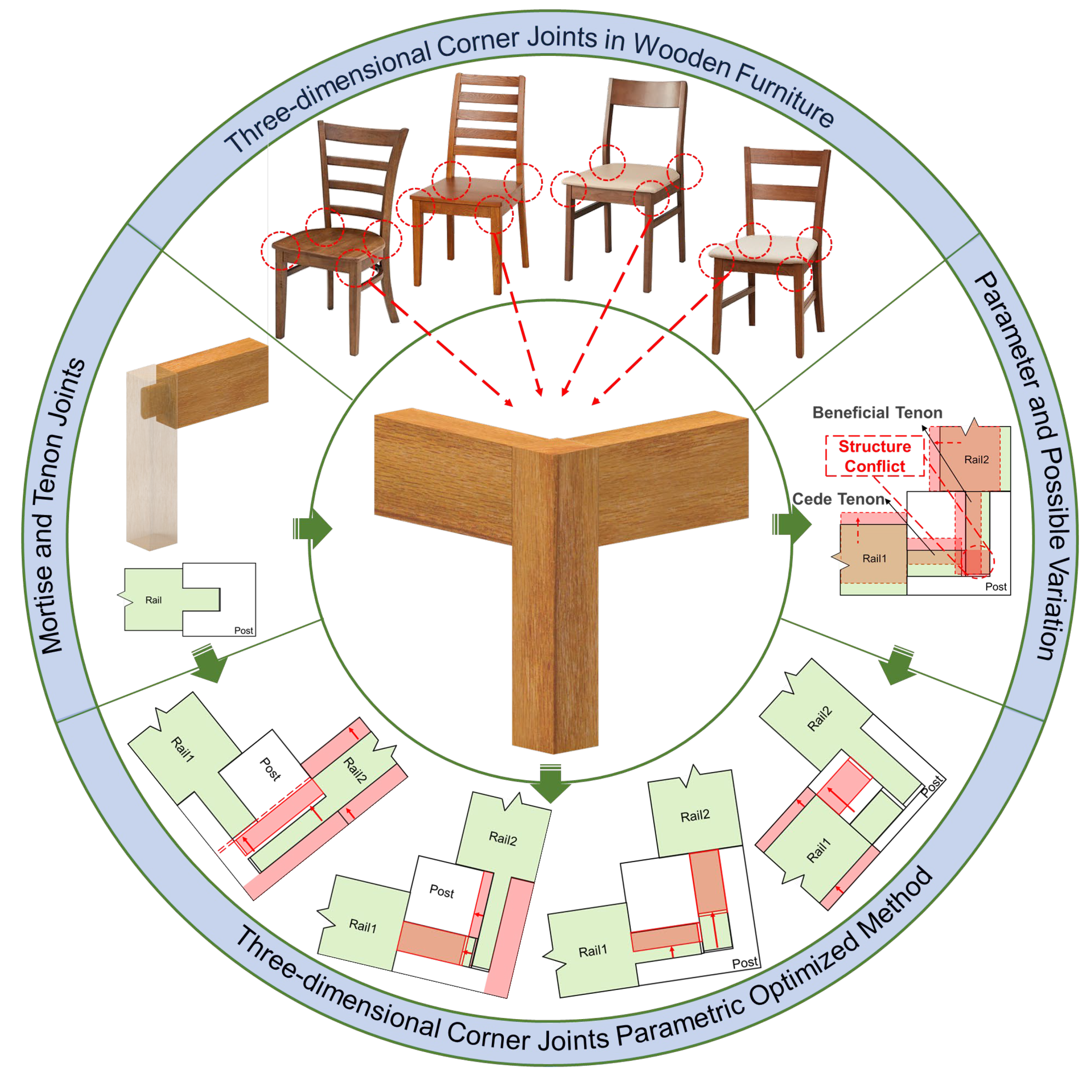
:1. Introduction
2. Materials and Methods
2.1. Steps
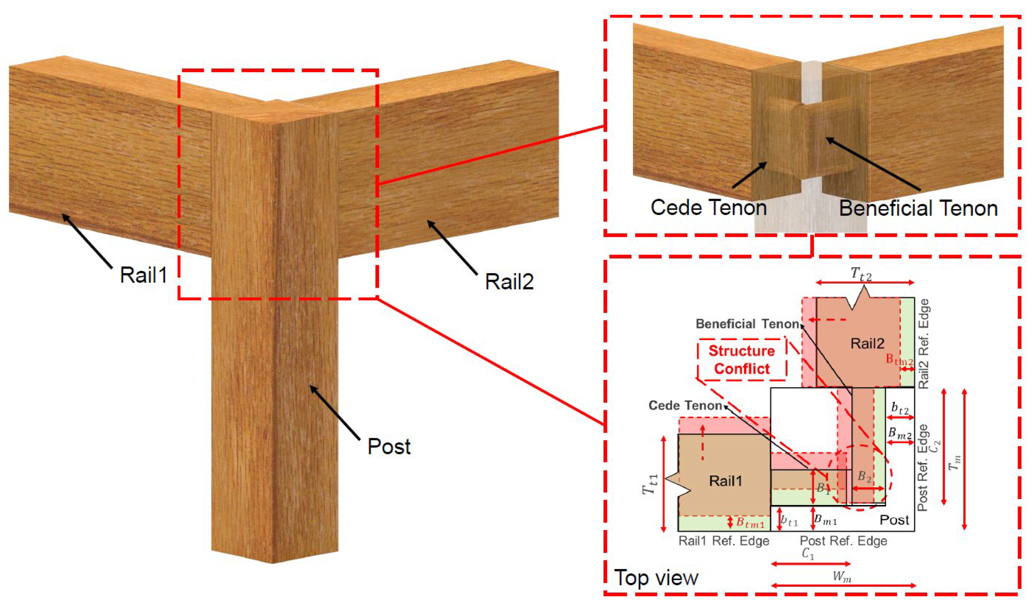
2.2. Three-Dimensional Corner Joints Parameter Value Optimized Method
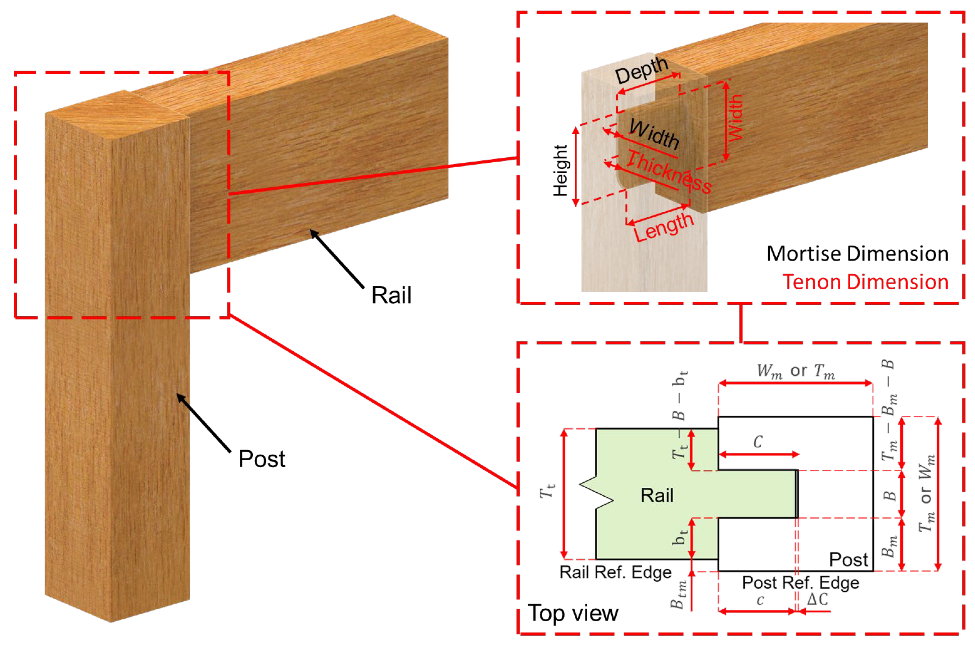
2.2.1. Mortise–Tenon Joint Parameter Basic Ideal Value Method
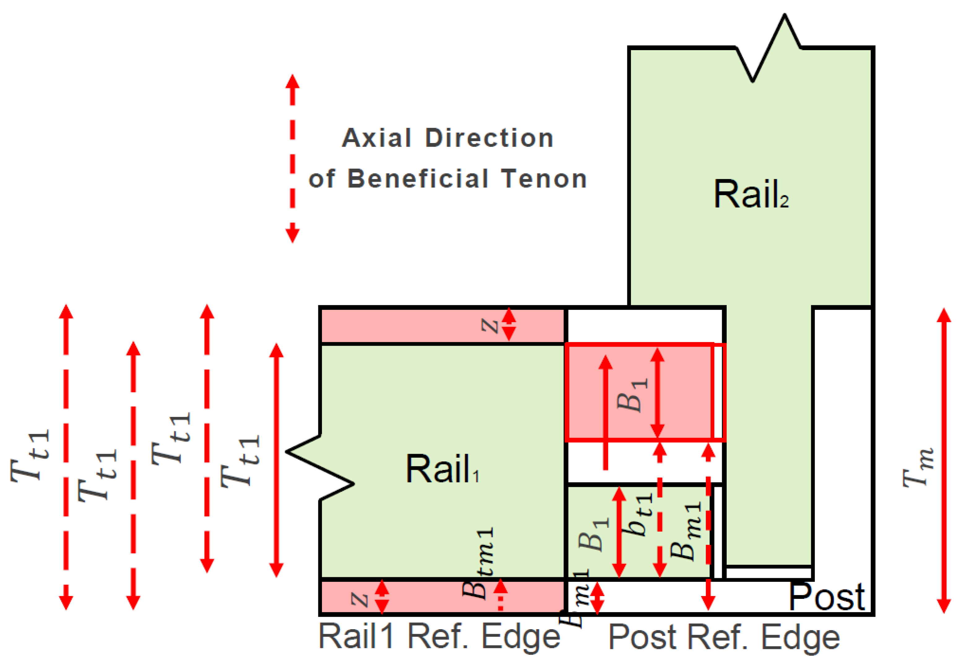
2.2.2. Parametric Optimized Method in the Axial Direction of the Beneficial Tenon
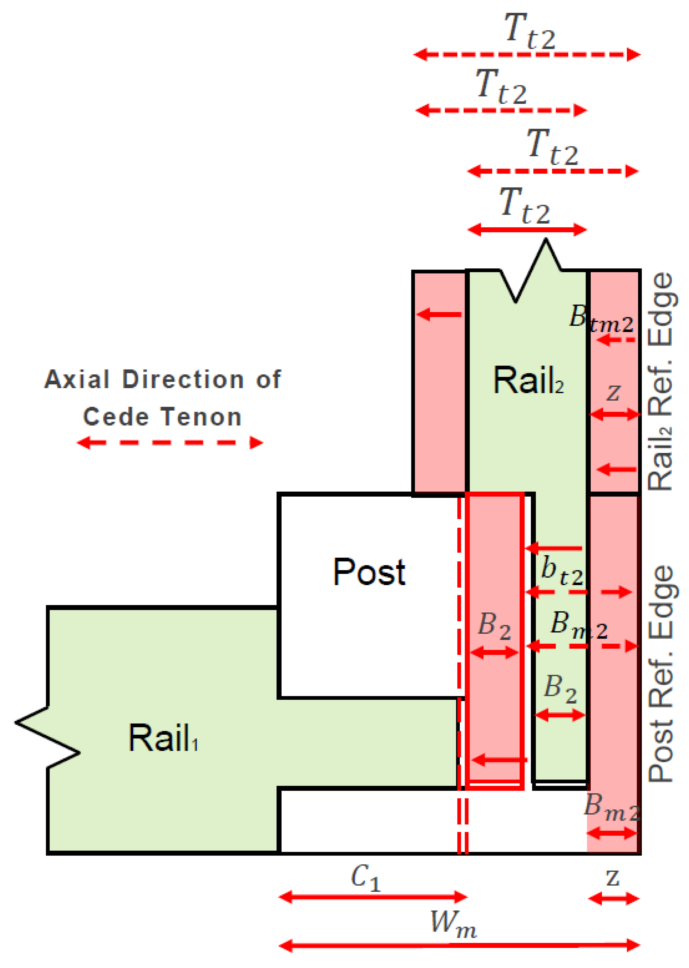
2.2.3. Parametric Optimized Method in the Axial Direction of Cede Tenon
2.3. Cases’ Basic Dimension Acquisition and Analysis Methods
3. Results
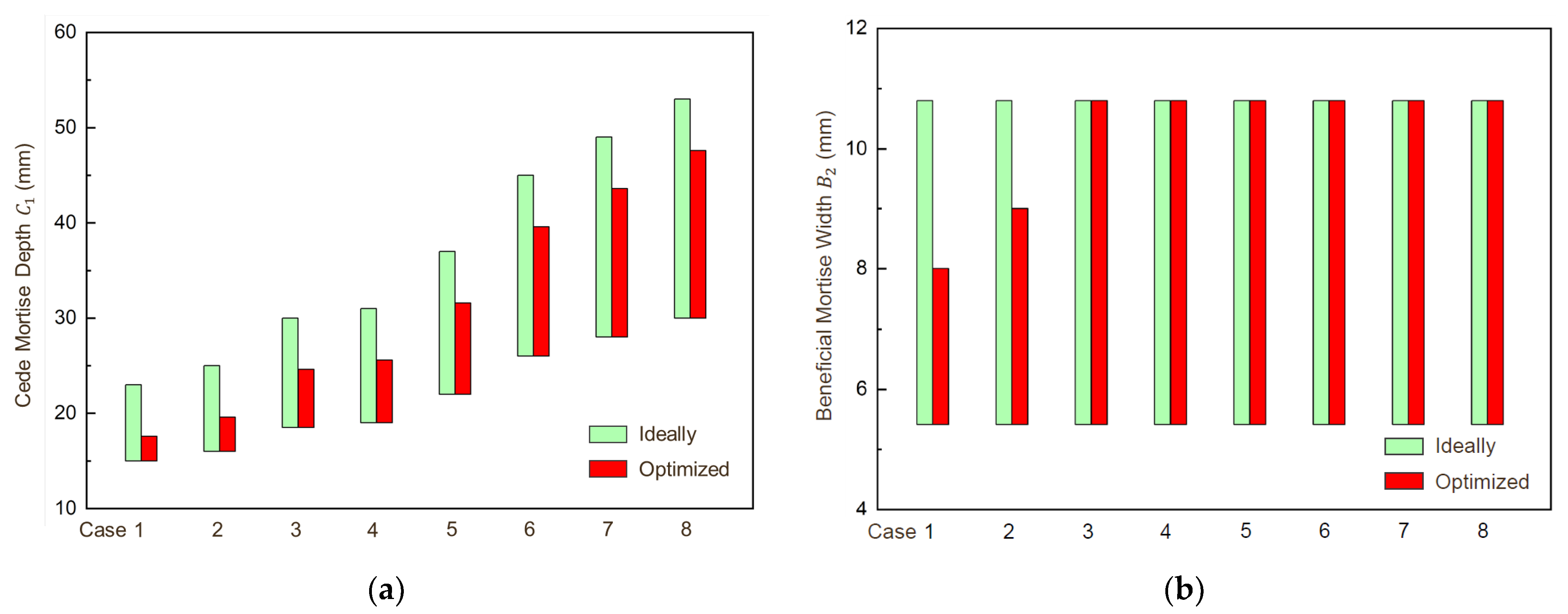
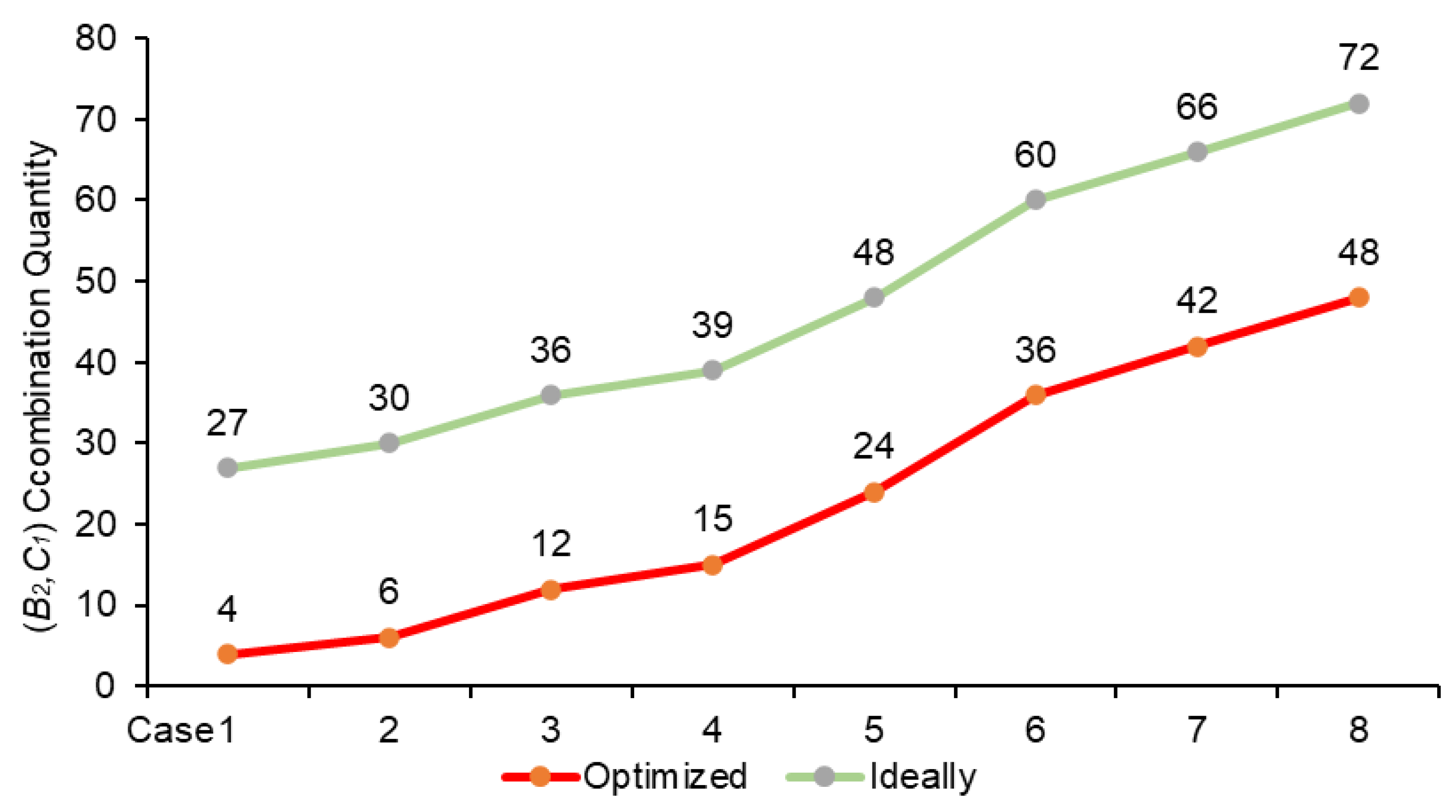
3.1. Cases’ Parameter Value in the Axial Direction of Cede Tenon
3.2. Cases’ Parameter Values in the Axial Direction of Beneficial Tenon
4. Discussion
4.1. Effect of Three-Dimensional Corner Joint in Parameter Values
4.2. Further Optimization for Parameter Values
5. Conclusions
- (1)
- Based on the ideal value range of the mortise–tenon joint parameters, this study further derived parameter value optimized methods for the beneficial tenon axis and the cede tenon axis, which theoretically narrowed the coverage range of at least four main parameters: , , , and .
- (2)
- The analysis of the cases’ data shows that in the axial direction of the cede tenon, the maximum depth of all cede mortises decreased by 5.4 mm, and the () combination kinds decreased by at least 23. When the post width is 28 mm and 30 mm, the width of the beneficial mortise is reduced by 2 mm and 1 mm, respectively, compared with the ideal value, and the () combination kinds are reduced to four and six, respectively. When the post width is smaller, the coverage range of is reduced from 0–12 mm with the ideal method to 0–5 mm with the optimized method, and depending on the different values of , the quantity of values can be reduced to a minimum of one and a maximum of three. When the post width is larger, the quantity of values that can take is reduced to a minimum of one. In the axial direction of the beneficial tenon, when is less than constant z, the parameter value range and quantity of values of decrease as decreases. Thus, the optimized method can significantly reduce the range of values in the cede tenon axis. The range of values in the beneficial tenon axis can also be reduced to a certain extent along with corresponding values, and the more dimension parameter setting values or standard values, the more the coverage range of dimension parameters will converge, and the fewer values will be required.
Author Contributions
Funding
Data Availability Statement
Acknowledgments
Conflicts of Interest
References
- Xiong, X.Q.; Yue, X.Y. Research and application progress of home intelligent manufacturing technologies in China. J. For. Eng. 2022, 7, 26–34. [Google Scholar] [CrossRef]
- Xiong, X.; Ma, Q.; Yuan, Y.; Wu, Z.; Zhang, M. Current situation and key manufacturing considerations of green furniture in China: A review. J. Clean. Prod. 2020, 267, 121957. [Google Scholar] [CrossRef]
- Zhu, Z.; Jin, D.; Wu, Z.; Xu, W.; Yu, Y.; Guo, X.; Wang, X. Assessment of surface roughness in milling of beech using a response surface methodology and an adaptive network-based fuzzy inference system. Machines 2022, 10, 567. [Google Scholar] [CrossRef]
- Li, R.; Zhao, S.; Yang, B. Research on the application status of machine vision technology in furniture manufacturing process. Appl. Sci. 2023, 13, 2434. [Google Scholar] [CrossRef]
- Wu, Q.; Liu, F.; Hu, R.; Yu, H. Research on performance optimization method of mechanical parts based on CAD/CAE integration. J. Mech. Strength 2021, 43, 1504–1509. [Google Scholar] [CrossRef]
- Xiong, X.; Yue, X.; Wu, Z. Current status and development trends of Chinese intelligent furniture industry. J. Renew. Mater. 2023, 11, 1353–1366. [Google Scholar] [CrossRef]
- Fu, W.-L.; Guan, H.-Y. Numerical and theoretical analysis of the contact force of oval mortise and tenon joints concerning outdoor wooden furniture structure. Wood Sci. Technol. 2022, 56, 1205–1237. [Google Scholar] [CrossRef]
- Lu, D.; Xiong, X.; Lu, G.; Gui, C.; Pang, X. Effects of NaOH/H2O2/Na2SiO3 bleaching pretreatment method on wood dyeing properties. Coatings 2023, 13, 233. [Google Scholar] [CrossRef]
- Yu, M.; Sun, D.; Zou, W.; Wang, Z.; Jiang, X.; Yao, L.; Kong, J. Mechanical analysis of new Chinese style wood chairs using ANSYS. J. For. Eng. 2021, 6, 178–184. [Google Scholar] [CrossRef]
- Xu, X.T.; Xiong, X.Q.; Zhang, Y.M.; Ren, G.J.; Cheng, Y.Q. Structural innovation and design improvement of detachable solid wood cabinet door with rectangular mortise and tenon joints. Furniture 2022, 43, 24–26+117. [Google Scholar]
- Tang, L.; Lu, L.; Guan, H. Modern optimized design and anti-bending property of traditional corner joints. J. For. Eng. 2022, 7, 166–173. [Google Scholar] [CrossRef]
- Tang, L.; Guan, H.; Wang, N.; Dai, P. Development of intelligent programming system for numerical controlled mortise and tenon joint. J. Beijing For. Univ. 2019, 41, 134–142. [Google Scholar] [CrossRef]
- Yuan, Z.; Sun, C.; Wang, Y. Design for manufacture and assembly-oriented parametric design of prefabricated buildings. Autom. Constr. 2018, 88, 13–22. [Google Scholar] [CrossRef]
- Geren, N.; Akçalı, O.O.; Bayramoğlu, M. Parametric design of automotive ball joint based on variable design methodology using knowledge and feature-based computer assisted 3D modelling. Eng. Appl. Artif. Intell. 2017, 66, 87–103. [Google Scholar] [CrossRef]
- Liu, X.; Tang, L.; Yi, Y.; Ni, Z. Intelligent design based on holographic model using parametric design method. J. Ambient Intell. Humaniz. Comput. 2019, 10, 1241–1255. [Google Scholar] [CrossRef]
- Kasal, A.; Smardzewski, J.; Kuşkun, T.; Erdil, Y.Z. Numerical analyses of various sizes of mortise and tenon furniture joints. BioResources 2016, 11, 6836–6853. [Google Scholar] [CrossRef]
- Hu, W.; Chen, B. A methodology for optimizing tenon geometry dimensions of mortise-and-tenon joint wood products. Forests 2021, 12, 478. [Google Scholar] [CrossRef]
- Guan, H. Modern furniture structures 1st chapter: Modern solid wood furniture structure—Joints and their requirements. Furniture 2007, 155, 54–59. [Google Scholar] [CrossRef]
- Smardzewski, J. Furniture Design; Springer: Dordrecht, The Netherlands, 2015; Volume 6, pp. 226–249. [Google Scholar] [CrossRef]
- Tang, L.; Guan, H. Intelligent method of determining dimension of mortise and tenon joint based on parameterization. J. Beijing For. Univ. 2021, 43, 143–154. [Google Scholar] [CrossRef]
- Song, M.; Buck, D.; Yu, Y.; Du, X.; Guo, X.; Wang, J.; Zhu, Z. Effects of Tool Tooth Number and Cutting Parameters on Milling Performance for Bamboo–Plastic Composite. Forests 2023, 14, 433. [Google Scholar] [CrossRef]
- Lee, I.-J. Using augmented reality to train students to visualize three-dimensional drawings of mortise–tenon joints in furniture carpentry. Interact. Learn. Environ. 2020, 28, 930–944. [Google Scholar] [CrossRef]
- Chen, B.; Xia, H.; Hu, W. The design and evaluation of three-dimensional corner joints used in wooden furniture frames: Experimental and numerical. BioResources 2022, 17, 2143–2156. [Google Scholar] [CrossRef]
- Xiong, X.Q.; Ren, J. Digital design technology of furnishing products in intelligent manufacturing. Chin. J. Wood Sci. Technol. 2021, 35, 14–19. [Google Scholar] [CrossRef]
- Rempling, R.; Mathern, A.; Ramos, D.T.; Fernández, S.L. Automatic structural design by a set-based parametric design method. Autom. Constr. 2019, 108, 102936. [Google Scholar] [CrossRef]
- Guan, H. Modern furniture structures 2nd chapter: Modern solid wood furniture structure—structures in details and on the whole. Furniture 2007, 156, 45–51. [Google Scholar] [CrossRef]
- Chen, B.; Guan, H. A novel method and validation for obtaining the optimal interference fit of round-end mortise-and-tenon joint. Wood Mater. Sci. Eng. 2023, 1–11. [Google Scholar] [CrossRef]
- Hu, W.; Liu, N.; Guan, H. Experimental and numerical study on methods of testing withdrawal resistance of mortise-and-tenon joint for wood products. Forests 2020, 11, 280. [Google Scholar] [CrossRef]
- Wang, Y.; Chen, J.; Fang, Z.; Wang, H. Status review of wooden furniture standardization in China. Chin. J. Wood Sci. Technol. 2021, 35, 73–78. [Google Scholar] [CrossRef]
- Xiong, X.Q.; Ma, Q.R.; Yuan, Y.Y.; Pan, Y.T.; Niu, Y.T. Digital design and manufacturing of furniture enterprises oriented to intelligent manufacturing. J. For. Eng. 2020, 5, 174–180. [Google Scholar] [CrossRef]
- Zhang, T.; Hu, W. Numerical study on effects of tenon sizes on withdrawal load capacity of mortise and tenon joint. Wood Res. 2021, 66, 321–330. [Google Scholar] [CrossRef]
- Xu, X.T.; Yan, X.X. Study on and probe into national standards of children’s furniture structural safety. For. Mach. Woodwork. Equip. 2021, 49, 43–46. [Google Scholar] [CrossRef]
- Xu, J.; Zhu, X.; He, R.; Ren, H.; Li, J. Optimization of oval mortise and tenon joint based on group technology. J. For. Eng. 2017, 2, 144–149. [Google Scholar] [CrossRef]
- Hitka, M.; Štarchoň, P.; Simanová, Ľ.; Čuta, M.; Sydor, M. Dimensional solution of wooden chairs for the adult bariatric population of slovakia: Observational study. Forests 2022, 13, 2025. [Google Scholar] [CrossRef]
- Gao, L.; Xu, W.; Li, R.; Huang, Q. Influcing factors of t-type parts joint strength of ellipse mortise and tenon. China For. Prod. Ind. 2019, 50, 19–22. [Google Scholar] [CrossRef]
- Smardzewski, J. Strength of profile-adhesive joints. Wood Sci. Technol. 2002, 36, 173–183. [Google Scholar] [CrossRef]
- Zhu, Z.; Buck, D.; Wang, J.; Wu, Z.; Xu, W.; Guo, X. Machinability of different wood-plastic composites during peripheral milling. Materials 2022, 15, 1303. [Google Scholar] [CrossRef]
- Li, R.; He, C.; Xu, W.; Wang, X.A. Prediction of surface roughness of CO2 laser modified poplar wood via response surface methodology. Maderas. Cienc. Tecnol. 2022, 24, 1–12. [Google Scholar] [CrossRef]
- Peng, W.; Yan, X. Preparation of tung oil microcapsule and its effect on wood surface coating. Polymers 2022, 14, 1536. [Google Scholar] [CrossRef]
- Yan, X.; Peng, W.; Qian, X. Effect of water-based acrylic acid microcapsules on the properties of paint film for furniture surface. Appl. Sci. 2021, 11, 7586. [Google Scholar] [CrossRef]
- Lin, T. Preliminary study on the parametric manufacturing process of traditional woodworking tenon. ICFXD 2021, 1, 140501–140511. [Google Scholar] [CrossRef]
- Gao, L.; Xu, W.; Wu, S.; Zhan, X.; Shen, Z. Research on the optimization of the mortise and tenon connection of solid wood furniture components. Furniture 2018, 39, 4–7. [Google Scholar] [CrossRef]
- Yi, L.; He, J.; Zhang, Z.; Zhang, J. Construction of digital model of round-backed using NX software and MBD technology. J. For. Eng. 2023, 8, 180–186. [Google Scholar] [CrossRef]
- Ren, J.; Xiong, X.Q. Digital design process and part family division of solid wood custom cabinet door based on multi-attribute overlapping clustering technology. BioResources 2020, 17, 5393. [Google Scholar] [CrossRef]
- Langová, N.; Réh, R.; Igaz, R.; Krišťák, Ľ.; Hitka, M.; Joščák, P. Construction of wood-based lamella for increased load on seating furniture. Forests 2019, 10, 525. [Google Scholar] [CrossRef]


| Case | Rail (mm) | Post (mm) | Case | Rail (mm) | Post (mm) | ||
|---|---|---|---|---|---|---|---|
| Tt | Wm | Tm | Tt | Wm | Tm | ||
| 1 | 18 | 28 | 28 | 5 | 18 | 42 | 35 |
| 2 | 30 | 30 | 6 | 50 | 22 | ||
| 3 | 35 | 28 | 7 | 54 | 27 | ||
| 4 | 36 | 36 | 8 | 58 | 28 | ||
| Case | Rail (mm) | Post (mm) | Mortise (Ideally) (mm) | Mortise (Optimized) (mm) | ||||||
|---|---|---|---|---|---|---|---|---|---|---|
| Tt2 | Wm | minB2 | maxB2 | minC1 | maxC1 | minB2 | maxB2 | minC1 | maxC1 | |
| 1 | 18 | 28 | 5.4 | 10.8 | 15 | 23 | 5.4 | 8 | 15 | 17.6 |
| 2 | 30 | 16 | 25 | 9 | 16 | 19.6 | ||||
| 3 | 35 | 18.5 | 30 | 10.8 | 18.5 | 24.6 | ||||
| 4 | 36 | 19 | 31 | 19 | 25.6 | |||||
| 5 | 42 | 22 | 37 | 22 | 31.6 | |||||
| 6 | 50 | 26 | 45 | 26 | 39.6 | |||||
| 7 | 54 | 28 | 49 | 28 | 43.6 | |||||
| 8 | 58 | 30 | 53 | 30 | 47.6 | |||||
| Case | Rail (mm) | Post (mm) | (B2, C1) Possible Values (Optimized) (mm) | ||
|---|---|---|---|---|---|
| Tt2 | Wm | B2 = 6 | B2 = 8 | B2 = 10 | |
| 1 | 18 | 28 | C1 = 15~17 | C1 = 15 | - |
| 2 | 30 | C1 = 16~19 | C1 = 16~17 | - | |
| 3 | 35 | C1 = 19~24 | C1 = 19~22 | C1 = 19~20 | |
| 4 | 36 | C1 = 19~25 | C1 = 19~23 | C1 = 19~21 | |
| 5 | 42 | C1 = 22~31 | C1 = 22~29 | C1 = 22~27 | |
| 6 | 50 | C1 = 26~39 | C1 = 26~37 | C1 = 26~35 | |
| 7 | 54 | C1 = 28~43 | C1 = 28~41 | C1 = 28~39 | |
| 8 | 58 | C1 = 30~47 | C1 = 30~45 | C1 = 30~43 | |
| Case | Tt2 (mm) | Wm (mm) | C1 (mm) | B2 (mm) | Btm2 (mm) | minbt2 (mm) | maxbt2 (mm) | bt2 Val. Qua. | Formula |
|---|---|---|---|---|---|---|---|---|---|
| 1 | 18 | 28 | 15 | 6 | 0 | 5 | 7 | 3 | (6b) |
| 5 | 0 | 2 | 3 | (6c) | |||||
| 7 | 0 | 0 | 1 | (6d) | |||||
| 8 | 0 | 5 | 5 | 1 | (6b) | ||||
| 5 | 0 | 0 | 1 | (6c) | |||||
| 17 | 6 | 0 | 5 | 5 | 1 | (6b) | |||
| 5 | 0 | 0 | 1 | (6c) | |||||
| 8 | 58 | 30 | 6 | 0 | 0 | 12 | 13 | (2c) | |
| 22 | 0 | 0 | 1 | (6a) | |||||
| 10 | 0 | 0 | 8 | 9 | (2c) | ||||
| 18 | 0 | 0 | 1 | (6a) | |||||
| 41 | 6 | 0 | 5 | 11 | 7 | (6b) | |||
| 5 | 0 | 6 | 7 | (6c) | |||||
| 11 | 0 | 0 | 1 | (6d) | |||||
| 10 | 0 | 5 | 7 | 3 | (6b) | ||||
| 5 | 0 | 2 | 3 | (6c) | |||||
| 7 | 0 | 0 | 1 | (6d) | |||||
| 47 | 6 | 0 | 5 | 5 | 1 | (6b) | |||
| 5 | 0 | 0 | 1 | (6c) |
| Case | Rail1 (mm) | Post (mm) | Mortise (mm) | (B1, C2) Qua. | |||
|---|---|---|---|---|---|---|---|
| Tt1 | Tm | minB1 | maxB1 | minC2 | maxC2 | ||
| 1 | 18 | 28 | 5.4 | 10.8 | 15 | 23 | 27 |
| 2 | 30 | 16 | 25 | 30 | |||
| 3 | 28 | 15 | 23 | 27 | |||
| 4 | 36 | 19 | 31 | 39 | |||
| 5 | 35 | 18.5 | 30 | 36 | |||
| 6 | 22 | 12 | 17 | 18 | |||
| 7 | 27 | 14.5 | 22 | 24 | |||
| 8 | 28 | 15 | 23 | 27 | |||
| Case | Tt1 (mm) | Tm (mm) | B1 (mm) | Btm1 (mm) | minbt1 (mm) | maxbt1 (mm) | bt1 Val. Quan. | Formula |
|---|---|---|---|---|---|---|---|---|
| 1 | 18 | 28 | 6 | 0 | 0 | 12 | 13 | (2c) |
| 10 | 0 | 12 | 13 | |||||
| 10 | 0 | 0 | 8 | 9 | ||||
| 10 | 0 | 8 | 9 | |||||
| 6 | 22 | 6 | 0 | 5 | 11 | 7 | (3a) | |
| 4 | 1 | 7 | 7 | |||||
| 10 | 0 | 5 | 7 | 3 | ||||
| 4 | 1 | 3 | 3 | |||||
| Hypo. | 18 | 6 | 0 | 5 | 7 | 3 | (3b) | |
| 8 | 0 | 5 | 5 | 1 | ||||
| 10 * | 0 | - | - | - | - |
Disclaimer/Publisher’s Note: The statements, opinions and data contained in all publications are solely those of the individual author(s) and contributor(s) and not of MDPI and/or the editor(s). MDPI and/or the editor(s) disclaim responsibility for any injury to people or property resulting from any ideas, methods, instructions or products referred to in the content. |
© 2023 by the authors. Licensee MDPI, Basel, Switzerland. This article is an open access article distributed under the terms and conditions of the Creative Commons Attribution (CC BY) license (https://creativecommons.org/licenses/by/4.0/).
Share and Cite
Xu, X.; Xiong, X.; Yue, X.; Zhang, M. A Parametric Optimized Method for Three-Dimensional Corner Joints in Wooden Furniture. Forests 2023, 14, 1063. https://doi.org/10.3390/f14051063
Xu X, Xiong X, Yue X, Zhang M. A Parametric Optimized Method for Three-Dimensional Corner Joints in Wooden Furniture. Forests. 2023; 14(5):1063. https://doi.org/10.3390/f14051063
Chicago/Turabian StyleXu, Xiutong, Xianqing Xiong, Xinyi Yue, and Mei Zhang. 2023. "A Parametric Optimized Method for Three-Dimensional Corner Joints in Wooden Furniture" Forests 14, no. 5: 1063. https://doi.org/10.3390/f14051063