Article

Simulating Wind Disturbances over Rubber Trees with Phenotypic Trait Analysis Using Terrestrial Laser Scanning

1
College of Mechanical and Electronic Engineering, Nanjing Forestry University, Nanjing 210037, China
2
Rubber Research Institute, Chinese Academy of Tropical Agricultural Sciences, Haikou 571101, China
3
Research Institute of Forestry Resource Information Techniques, Chinese Academy of Forestry, Beijing 100091, China
*
Author to whom correspondence should be addressed.
These authors contributed equally to this work.
Forests 2022, 13(8), 1298; https://doi.org/10.3390/f13081298
Submission received: 16 July 2022 / Revised: 3 August 2022 / Accepted: 9 August 2022 / Published: 15 August 2022
(This article belongs to the Special Issue Advances in Forest Fire and Other Detection Systems)

Abstract

:
Hurricanes often devastate trees throughout coastal China; accordingly, developing a method to quantitatively evaluate the changes in tree phenotypic characteristics under continuous strong winds is of great significance for guiding forest cultivation practices and mitigating wind hazards. For this research, we built a lifting steel truss carrying a large forced draft fan near a rubber plantation on Hainan Island, and we aligned three selected small rubber trees in a row in front of the fan (with separation distances from the forced draft fan outlet of approximately 1.3, 3.3, and 5.3 m) to explore the susceptibility of rubber trees to the mechanical loading of hurricane-level winds. By adjusting the power of the forced draft fan, four wind speeds were emitted: 0 m/s, 10.5 m/s, 13.5 m/s, and 17.5 m/s. Meanwhile, point clouds of the three rubber trees under different continuous wind speeds were acquired using two terrestrial laser scanners. Computer algorithms were applied to derive the key parameters of the three rubber trees, namely, the zenith and azimuth angles of each leaf, effective leaf area index (LAI), windward area of each tree, volume of the tree canopy, and trunk tilt angle, from these point clouds under all four wind speeds. The results show that by increasing the wind speed from 0 m/s to 17.5 m/s, the leaf zenith angles of the three rubber trees were unimodally distributed with the peak concentrated at 0°, while the leaf azimuth angles were bimodally distributed with the peaks concentrated at 0° and 360°. The effective LAI values of the three trees increased from 2.97, 4.77, and 3.63 (no wind) to 3.84, 5.9, and 4.29 (wind speed of 17.5 m/s), respectively, due to a decrease in the vertical crown projection area caused by the compression of the tree canopy. We also found that the effective LAI, windward area, and canopy volume of the third rubber tree (the tree farthest from the forced draft fan) varied less than those of the other two trees, reflecting the attenuation of the wind speed by the crowns of the two trees closer to the fan. The experimental results also indicate that the joint use of light detection and ranging (LiDAR) data with computer graphics algorithms to analyse the dynamic changes in tree phenotypic characteristics during the passage of a hurricane is promising, enabling the development of a novel strategy for mitigating wind hazards. The proposed method with the designed device capable of producing an adjustable wind speed also has the potential to study the impacts of wind damage under various forest conditions by further modifying the tree spacing and tree species.

1. Introduction

Wind is a ubiquitous natural force [1] that can cause intermittent damage to forests and even delay the mortality of trees by 3–9 months after a hurricane has occurred [2]; moreover, wind can have a significant impact on the carbon budget of forests [3]. In addition, hurricanes can cause trees to sway and weaken their roots or stems [4]. Rubber trees (Hevea brasiliensis Müll. Arg.) are economically important tropical trees that produce natural rubber [5] and are major sources of latex and wood in many tropical countries throughout Southeast Asia, South America, and Africa [6]. Hainan Island is China’s largest rubber production base, featuring a plantation area of 5.26 × 10⁵ hectares as of 2019, forming a tremendous artificial ecosystem [7]. However, as an island near the equator in the South China Sea, Hainan is subjected to a coastal subtropical monsoon climate with fast-moving air currents. The climate in the South China Sea is highly complicated and variable and frequently experiences severe weather, such as typhoons, rainstorms, and strong convection. Unfortunately, typhoons that form in the South China Sea and move northward make landfall on Hainan.
To the east of Hainan is the Pacific Ocean, which features a tropical and subtropical climate and has an average sea surface temperature of 19 °C. Under high temperatures and high humidity, an ultralow-pressure centre can form, generating a violent tropical storm. A large number of typhoons are formed in the Pacific Ocean, accounting for approximately 70% of the world’s total. The typhoons that form in the Pacific Ocean and move westward under the influence of the subtropical high [8] affect Hainan Island, and the rubber plantations on this island inevitably suffer damage as a consequence. Since the 1960s, Hainan Island has been subjected to the havoc of more than 100 hurricanes. For example, on October 18, 2016, Super Typhoon Sarika made landfall in Wanning city, Hainan Province, causing direct economic losses of CNY 4.559 billion in the province [9]; upon making landfall, the maximum wind near the centre was immensely strong 14 (45 m/s, severe typhoon level), and the minimum pressure at the centre was 960 hPa. On 18 July 2014, Hurricane Rammasun (International Identification Number: 201409) had a minimum atmospheric pressure of 899 hPa when the hurricane made landfall; the direct economic loss to Hainan Island was CNY 10.828 billion, and the loss of live wood growth reached 4.763 million m3 in Wenchang city alone [10]. Therefore, to predict and mitigate the effects of wind damage on rubber trees, it is necessary to consider the phenotypic changes of clonal rubber trees in different wind fields.
Previous studies have indicated that one of the key factors in predicting and mitigating the damaging effects of wind on forests is to understand the underlying causes of forest damage caused by wind [11]. At present, the methods used to research hurricane-induced damage to forests can be divided into three categories based on the study scale, i.e., large scale, forest plot scale, and individual tree scale.
On a large scale, remote sensing techniques such as light detection and ranging (LiDAR) data [12] or satellite imageries [13] are primarily combined with meteorological data files to quantitatively or qualitatively analyse the effects of different degrees of forest damage after the passage of a hurricane. At the forest stand scale, mathematical models are usually established to simulate the effect of wind damage on the forest plots and analyse the effects of hurricanes on forest ecosystem services and biodiversity indicators, such as the vibration frequency of tree bodies, multiphysics coupling between the fluid dynamics and structural mechanics, and quantitative evaluations of wind hazards in forest regeneration and succession [14]. At the individual tree scale, the branches and leaves are taken as the experimental objects at the fine scale and are principally studied; ecophysiological and morphological trait variations at a plant organ level under blustery wind produced by powered fan or wind tunnel [15] are analysed. The existing approaches used to analyse the aforementioned three categories are summarised in Table 1.
In summary, many studies have proposed methods for simulating hurricane-induced damage to forests, and all of these approaches have notable drawbacks with nonnegligible effects on the modelling results. For instance, when using satellite-based LiDAR data to study the effect of a passing hurricane on a forest, the satellite imagery data, which are collected at only a certain moment over a long scanning interval, are always obscured by weather conditions (cloudy or dust whirls) and are nonsequential in time. Nevertheless, hurricanes are continuous phenomena, and thus discontinuous satellite data are not able to probe how the forest structure varies during a hurricane under a time span. Furthermore, because forests irregularly span such extensive areas and satellites collect data along a stationary orbit, the sampled data satisfy neither stochastic sampling nor stratified sampling [13]; consequently, the existing research results are almost certainly not universally applicable due to the differences in tree species compositions and geographical or meteorological conditions. Additionally, hurricanes are generally accompanied by rainstorms, in which the transmission performance of a laser signal is atrocious, and atmospheric circulations distort and induce jitter in laser beams, which directly affects the accuracy of remote sensing satellite data or LiDAR data collection. From another perspective, most of the research based on satellite remote sensing data has explored the changes in the forest canopy, which is routinely deemed a porous medium [32,33], and thus a description of its specific internal structure is arduous. Other wind damage simulation models established based on computer simulations are frequently intended to represent only one type of tree species; accordingly, further studies are needed to explore whether these models achieve the expected effect and to consider the many uncontrollable external factors ignored by the model when a hurricane truly occurs [34].
As a remedy for the generalised shortcomings of the existing methods for simulating the wind damage incurred by a forest, a comprehensive approach was established by the synergetic building of a lifting steel truss loading a forced draft fan to create a strong air current with an adjustable wind speed and incorporating terrestrial laser scanning techniques to collect sequential data for the recording of the status of target rubber trees under multi-hazard hurricane environments. This approach has the merits of avoiding complex and cumbersome wind tunnel laboratory measurements and produces a flexible trial platform to study tree morphology under hurricane activities without the adverse efficacy of concomitant cloudburst rainfall. Furthermore, we obtained the phenotypic traits, e.g., the canopy volume, branch inclination angle, leaf azimuth angle, zenith angle, and effective leaf area index (LAI), using computer graphics algorithms to investigate the internal structural variations in trees subjected to storms at a fine scale, enabling assessments of the vulnerability and susceptibility of trees under uncertain abiotic stressors originating from wind strike damage. The overall workflow of our approach is shown in Figure 1.

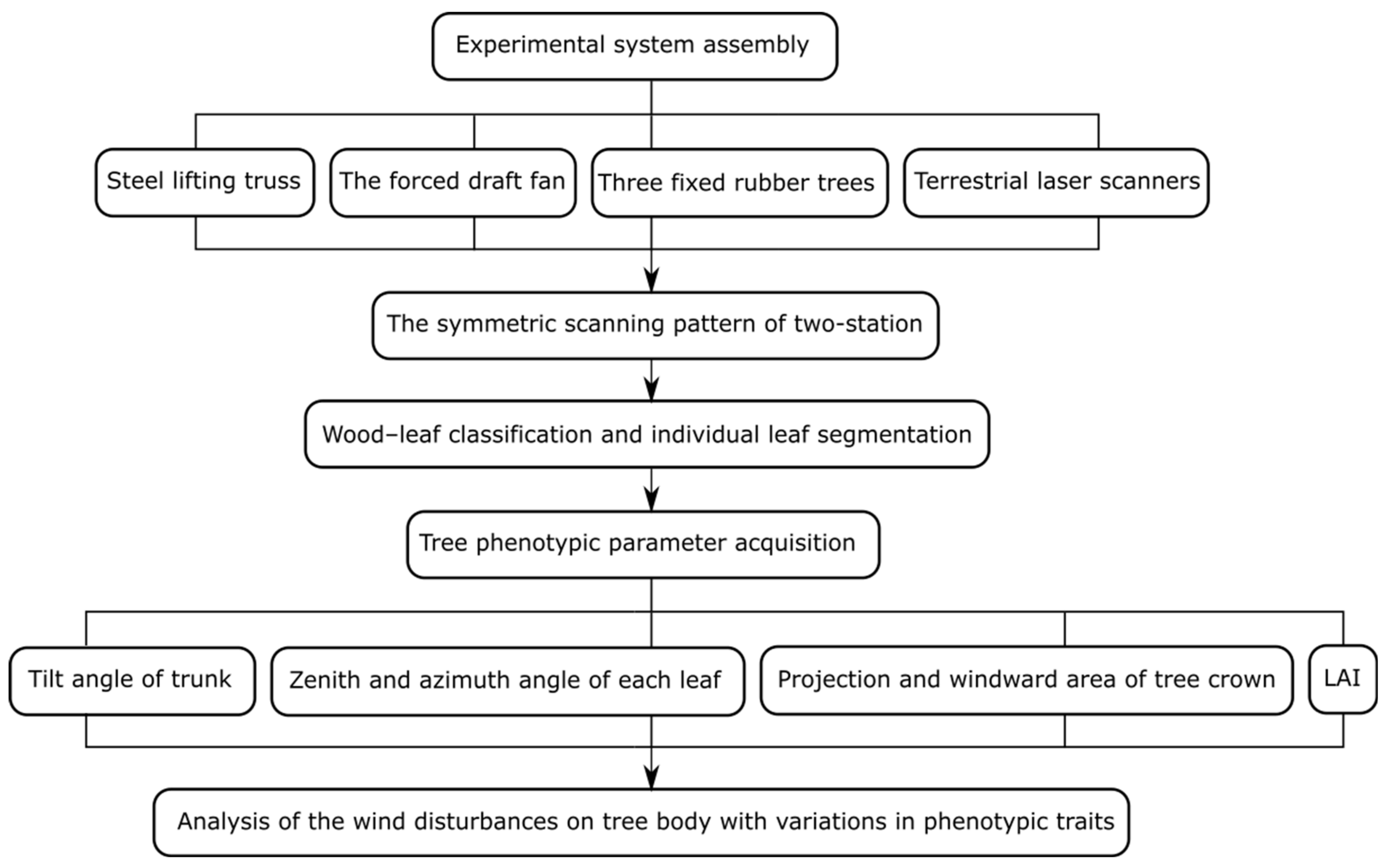
2. Materials and Methods

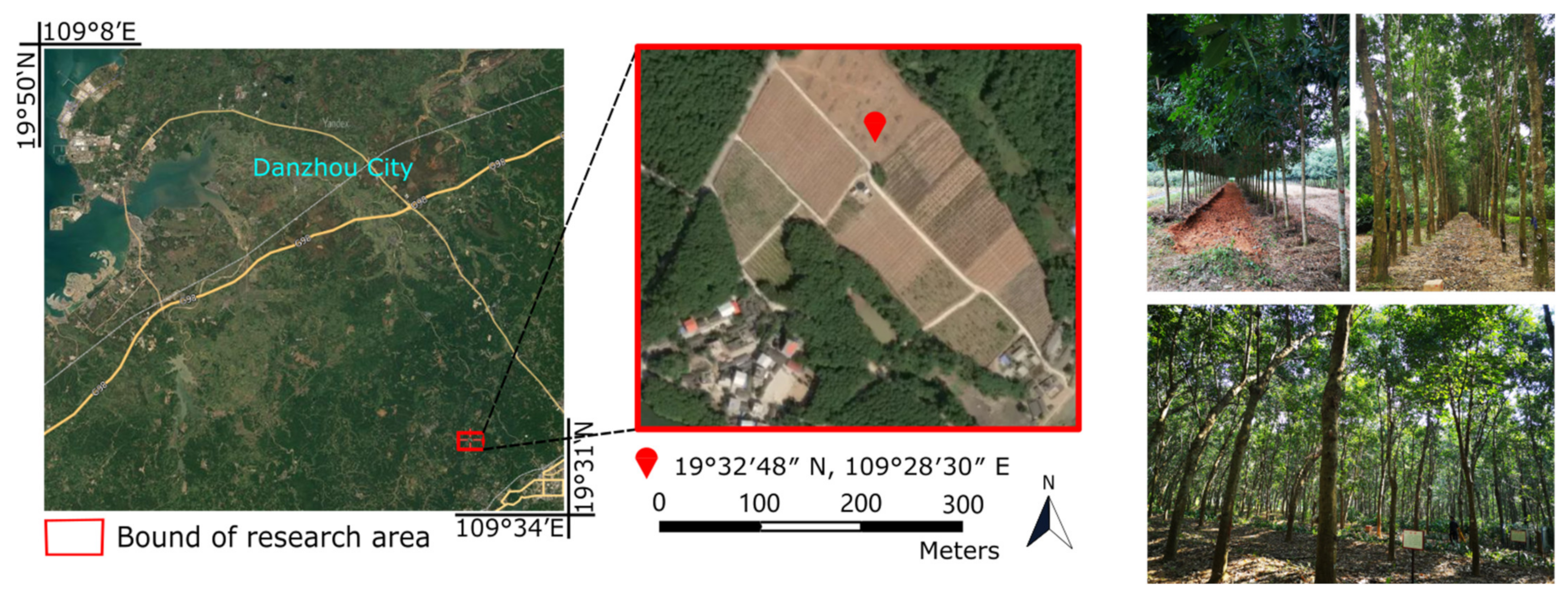
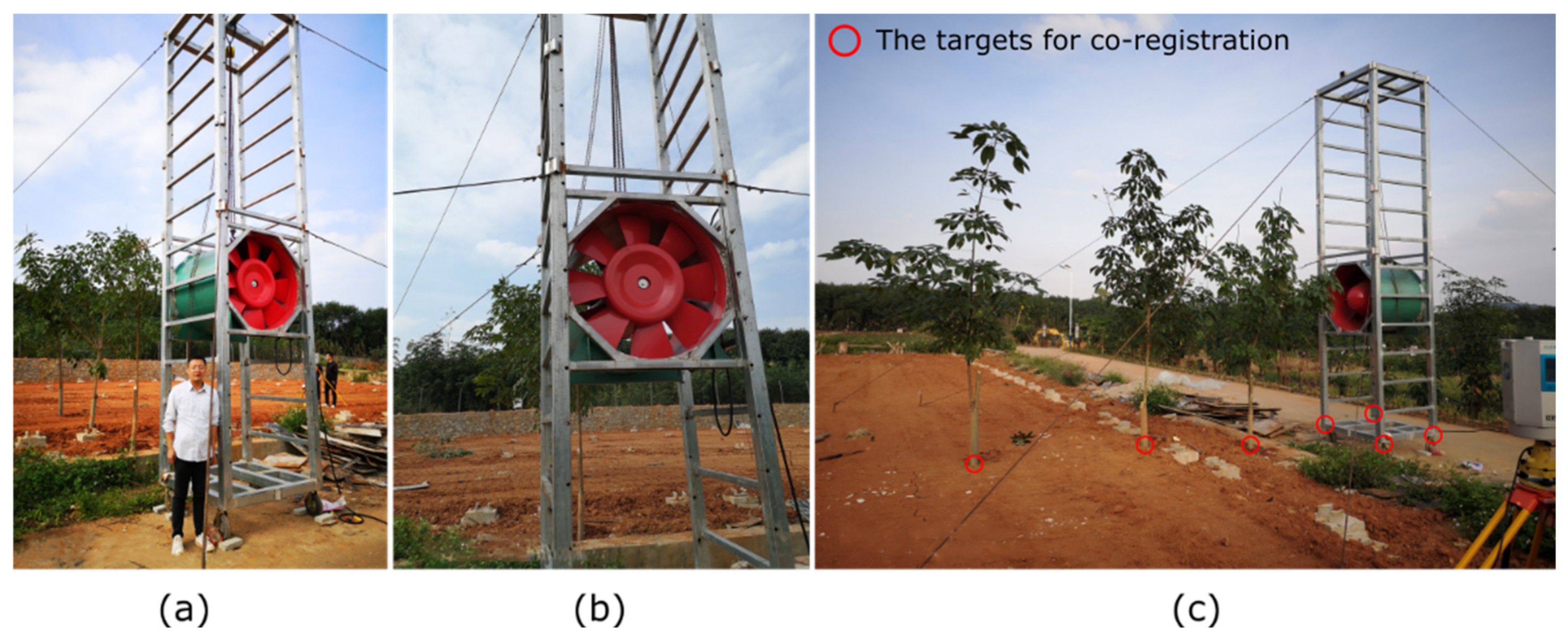
2.1. Study Area and Data Collection

The study area is located within a rubber tree plantation in Danzhou city (19°32′47.89″ N, 109°28′29.33″ E), Hainan Province, which is the main natural rubber production area in China and bears an important national mission in ensuring the safety and provision of natural rubber resources (Figure 2). The protected natural rubber production area of Hainan Province is 8.4 million acres (accounting for 46.7% of the national total of 18 million acres), of which more than 1 million acres are situated within Danzhou. The topography within 3.2 km of Danzhou is essentially flat, with a maximum relief of 14.9 m and an average elevation above sea level of 35.1 m; the land use within this 3.2 km radius is predominantly farmland (59%), artificial surfaces (18%), and water (12%). The area within 16.1 km is likewise essentially flat (260 m) and comprises farmland (48%) and trees (22%). Within 80.5 km, some significant variations in elevation occur (1266 m), and the land use is mostly trees (47%) and farmland (31%). In Danzhou city, the summers are long, hot, oppressive, humid, and mostly cloudy, whereas the winters are very cold and mostly clear. Over the course of the year, the temperature typically varies from 0 °C to 33.3 °C and is rarely below −3.3 °C or above 36.1 °C. The hot season lasts from May to September, with an average daily high temperature above 28.3 °C. The cool season lasts from December to March, with an average daily high temperature below 14.4 °C. Rain falls throughout the year in Danzhou; most rainfall occurs in June, with an average rainfall of 175.26 mm, while the least rainfall is measured in December, with an average rainfall of 25.4 mm. The brighter period of the year lasts from late April to mid-September, with an average of more than 5.1 kWh per square metre of incident shortwave energy per day. The darker period of the year, which lasts from early November to mid-February, averages less than 3.4 kWh per square metre of incident shortwave energy per day. The windier part of the year lasts from February to mid-May, with average wind speeds of more than 11.3 km/h, while the rest of the year (for a total of 8.5 months) is relatively calm.
The forced draft fan (red cylinder shown in Figure 3) was produced by Shaoxing Shangyu Yijie Ventilation Equipment Co., Ltd., located in Zhejiang, China, which has greater power than most industrial fans on the market. The forced draft fan model was HTF-I-(A)-11A, with a diameter of 110 cm, power of 15 kW and volume of 50,000 m3/h. The fan blades rotate at 1450 r/min, the full pressure and static pressure are 449–676 Pa, and the fan weighs 500 kg. The fan is generally applied as equipment in buildings for fire prevention, which is generally installed in the corridor of the building. When a fire occurs, the fan function should be activated to yield a huge roar of noise pollution to quickly discharge the smoke from the building to guarantee fire protection and reduce smoke-induced harm. The steel lifting truss (Figure 3) was later installed, with 1.25-m-long, 1.30-m-wide, and 5.70-m-high measurements and was fixed with 8 lengths of 6×37 steel wire rope (i.e., each length of steel wire rope consisted of 6 strands, and each strand was composed of 37 steel wires) for stable operation. The entire project took us over a year for transportation, assembly, design, installation, and adjustment to the power supply configurations of the whole hardware system.
A typical clonal rubber tree species was selected for this study. As the heavily forced draft fan and lifting steel truss need electricity to run at a steady rate with a power cable and 8 fixed steer wire ropes, a total of three five-year-old rubber trees from the rubber plantation were removed by directly cutting the base of the trunk of the three small rubber trees without root digging and immediately inserting the trunk into the three metal tubes. Since we could not find rubber trees with identical morphology and tree growth and appearance in nature are influenced by light, competition factors, nutrient distribution, physiological conditions and allometric growth models, the randomness of tree topologies under wind loading was demonstrated, and the structure of the three rubber trees shown in Figure 3c is somewhat different. The three fixed metal tubes installed in the ground had a height of 70 cm and were placed along the same line at a spacing of 2 m so that the three rubber trees were arranged linearly. The average height of the three experimental trees was 4 m. The spacing between adjacent trees was also 2 m according to the planting spacing of rubber trees on the line, and the distance between the forced draft fan and the closest tree was 1.3 m. The direction of the wind emitted by the forced draft fan was from south to north, which was in line with the arrangement of the three experimental trees. The three experimental trees were named (from south to north) Tree 1, Tree 2, and Tree 3, and Tree 1 was the closest to the forced draft fan. More detailed information on the forced draft fan can be found in Table 2.
The data were collected in October 2021 with two HS450 high-precision 3D laser scanners (Wuhan Hi-target Digitalcloud Technology Co., Ltd., Hubei, China) featuring a vertical field of view (FOV) of approximately −40° to +60°, a horizontal FOV of 360°, a scanning rate of 500,000 points per second, and a range measurement accuracy of ±8 mm at a distance of 1 m. The laser beam divergence at the scanner exit, and the minimum measurement distance were 0.35 mrad and 1.5 m, respectively. The minimum angular resolution during scanning was 0.0192°. Our LiDAR data were obtained from two HS450 scanners located on opposite sides of the target trees and pointing towards the centre of the tree crowns. The scanning setup adopted a close-range symmetrical scanning pattern (a distance of 5 m from the middle Tree and 1.57 m above the ground) with a multi-scan co-registration procedure according to the relatively static corners of the steel truss and three fixed cubes marked with red circles in Figure 3c. Due to the study of small rubber trees no higher than 4.1 m, each scan with a vertical field of view of −40° to +60° enabled complete coverage of the target trees by laser beams. The position of each HS450 scanner was slightly adjusted to obtain a more suitable perspective for the complete phenotypic characterization of the three trees while reducing occlusions between the rubber trees. Finally, we set the forced draft fan frequency to 0 Hz, 30 Hz, 45 Hz, and 60 Hz corresponding to emitted wind speeds of 0 m/s, 10.5 m/s, 13.5 m/s, and 17.5 m/s, respectively. The point clouds of the experimental tree under wind loading at different velocities were obtained, and the specific parameters of each scan are recorded in Table 2.

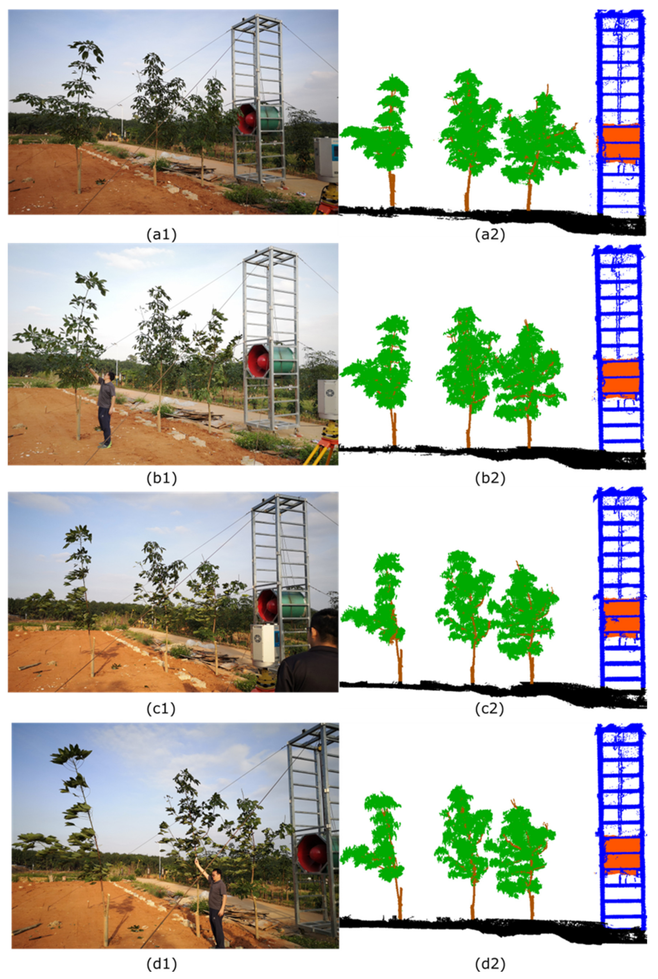
2.2. Data Preprocessing

In addition to the experimental trees, the raw LiDAR point clouds contained points corresponding to a large number of objects, including the forced draft fan and the surveyors. The software used for the co-registration of point clouds was the HS450 scanner’s supporting software, which was independently developed by Wuhan Hi-target Digitalcloud Technology Co., Ltd. Above all, the point clouds of the experimental trees were manually extracted from the raw LiDAR data by the open source software CloudCompare (version 2.10 alpha). Then, the experimental tree point clouds were separated into branch point clouds and leaf point clouds with a graphics-based wood–leaf classification method [35], which was implemented in MATLAB (the MathWorks Inc., Natick, MA, USA). Sub-sample cross-validation combined with the semi-supervised SVM algorithm was used to classify these scanned data. For the optimal performance of the classification algorithm, we set the neighbourhood domain to 11 cm and average spatial sampling to 1.21 cm. After the wood and leaves were classified, we measured some basic data on the three experimental trees, as listed in Table 2.
To reduce the impact of noise within the point cloud and for further analysis, because a wood–leaf classification was not sufficient, individual leaf segmentation was also needed. The algorithm we used to segment leaves was a computer graphics-based algorithm [36] consisting of three main stages.
First, the central area points of the leaves were extracted from the leaf point clouds with a spherical neighbourhood model featuring an adaptive radius. We randomly measured the width of several leaves and defined the average leaf width as d . The radius of the spherical neighbourhood model was 1/4 d . The points in each spherical neighbourhood model should have planar spatial features, be as close to the centre of each spherical neighbourhood model as possible and be evenly distributed. The centre of each spherical neighbourhood model should be close to the fitting plane. Second, the density-based spatial clustering of applications with a noise (DBSCAN) algorithm was used to cluster the central area points of the leaves, thereby obtaining the centre point corresponding to each leaf surface. Finally, individual leaves were segmented by a 3D watershed algorithm.
Leaf point clouds suffer from noise due to the movement of the leaves under the action of wind. To reduce the impact of noisy point cloud data, we removed individual point clusters containing fewer points than the noise threshold. The threshold varied according to the different experimental trees and to the different forced draft fan operating frequencies, i.e., at forced draft fan frequencies of 0 Hz, 30 Hz, 45 Hz, and 60 Hz (0 m/s, 10.5 m/s, 13.5 m/s, and 16.5 m/s), we set up noise thresholds of 35, 20, 10, and 10, respectively. The higher the wind, the faster the frequency at which the blades rotate and the more the overall structural complexity of the tree increases; as a result, there are fewer points in each isolated point cloud group scanned by the HS450 and a greater number of isolated point cloud groups, necessitating a smaller noise threshold.

2.3. Calculation of Tree Morphology Parameters

The tree morphology parameters we calculated were divided into two categories: photosynthetic and non-photosynthetic [37]. After identifying point clouds corresponding to individual leaves, we calculated the zenith angle and azimuth angle of each leaf for each experimental tree. Each leaf is conceptually represented by a small flat plate [38], so the leaf zenith angle is the angle (between 0° and 90°) between the vertical and the normal vector of that plate. We calculated the normal vector for each point and defined the average normal vector of all points belonging to each single-leaf point cloud as the normal vector of the single-leaf point cloud.
For scanned points p i l e a f x i , y i , z i P l e a f , i = 1 , 2 , 3 n l e a f , the single-leaf point cloud is defined as P l e a f , and a total of n l e a f points belong to the set of P l e a f . The points in the neighbourhood of the point p i l e a f within a radius r are defined as p j x j , y j , z j , j = 1 , 2 , 3 m . The covariance matrix C p of the neighbourhood of point p i l e a f is defined as C p = 1 m j = 1 m p j u p j u T , where u = 1 / m j = 1 m p j denotes the mean of p i l e a f neighbours and m is the number of points in the neighbourhood of the point p i l e a f . Here, we utilised eigenvalue decomposition to define a new coordinate system in which the axis directions are given by eigenvectors and point variances along axes are given by corresponding eigenvalues. Let e k , i be the eigenvector of C p and λ k , i be the corresponding eigenvalue, where k = 0 , 1 , 2 and λ 0 , i λ 1 , i λ 2 , i . λ k , i quantitatively shows the data variance along the axis e k , i . e 0 , i e i x , e i y , e i z corresponds to the smallest eigenvalue λ 0 , i and approximates the normal vector at p i l e a f . e 0 l e a f is the normal vector of the single-leaf P l e a f and is formulated as follows:
e 0 l e a f = 1 n l e a f i = 1 n l e a f e 0 , i
θ z e n i t h l e a f , the leaf zenith angle of P l e a f , can be expressed as follows:
θ z e n i t h l e a f = 180 π × a r c c o s e 0 l e a f · u v e r t i c a l e 0 l e a f × u v e r t i c a l
where u v e r t i c a l 0 , 0 , 1 is the vertical direction.
The leaf azimuth angle is the clockwise angle between north and the projection of the single-leaf principal axis onto the horizontal plane. For scanned points p k b r a n c h x k , y k , z k P b r a n c h , k = 1 , 2 , 3 n b r a n c h , the branch point cloud is defined as P b r a n c h , and the cluster of n b r a n c h points belongs to the set P b r a n c h . We calculated the Euclidean distances of p i l e a f and p k b r a n c h , thereby obtaining a matrix consisting of d i s t p i l e a f , p k b r a n c h totalling n l e a f × n b r a n c h values, and we defined the smallest value in the matrix as d i s t m i n . The point in each single-leaf point cloud corresponding to d i s t m i n is recorded as the petiole tip p t i p x t i p , y t i p , z t i p . We calculated the Euclidean distance from p t i p to each of the remaining points in the single-leaf point cloud and recorded the point corresponding to the longest distance to p t i p as the upper apex of that leaf p a p e x x a p e x , y a p e x , z a p e x . Thus, the vector of the principal axis of the leaf is v x a p e x x t i p , y a p e x y t i p , z a p e x z t i p . Since the X O Y plane represents the horizontal plane in our data, the projection of the single-leaf principal axis onto the horizontal plane is v X O Y x a p e x x t i p , y a p e x y t i p . Therefore, the azimuth angle θ a z i m u t h l e a f of each leaf is calculated using the following equation:
θ a z i m u t h l e a f = arccos v X O Y · u y v X O Y u y , i f   x a p e x x t i p > 0 2 π arccos v X O Y · u y v X O Y u y , o t h e r w i s e
where u y 0 , 1 represents north on the horizontal plane.
In the wind field, the height, volume, windward area, and other parameters of the object all affect the destructive force of wind on a tree. We computationally analysed the tree crown, which is an important object under a wind load, and obtained some parameters, including the image-based windward area, effective LAI, and crown volume, to better analyse the effects of wind on the experimental trees.
The horizontally projected image of an experimental tree in the wind direction is defined as I h o r . The horizontally projected image is a rectangle whose four edges closely fit the canopy boundary, which means that the width and length of I h o r are equal to the east–west width of the experimental tree crown (as explained in Section 2.1, the three experimental rubber trees in front of the forced draft fan are aligned north–south) and the rubber tree crown length (i.e., the tree height minus the clear bole height), respectively. The length and width of each rubber tree crown in the canopy were measured in the east–west direction and recorded as C L h o r and C W E W h o r , respectively. By traversing all the pixels, we next calculated the total number of pixels of the projected image n u m p i x e l h o r , the number of leaf pixels n u m l e a f p i x e l h o r and the number of branch pixels n u m b r a n c h p i x e l h o r . Hence, the projection area of the windward surface of the canopy, S1, is obtained using Equation (4).
S 1 = n u m b r a n c h p i x e l h o r + n u m l e a f p i x e l h o r n u m p i x e l h o r × C L h o r × C W E W h o r
The effective LAI is defined as the total one-sided leaf area per unit ground surface area. For a point p i l e a f x i , y i , z i P l e a f , the magnitudes of the variances, which are v a r x i , v a r y i and v a r z i , are calculated and judged, the smallest value of v a r x i , v a r y i or v a r z i is found, and the plane corresponding to the remaining two values is set as the projection plane. For example, if v a r y i is the minimum value, the X O Z plane is set as the projection plane. All the single-leaf points P l e a f are projected onto the X O Z plane, yielding a projection plane domain formed by the projected single-leaf points. The 2D Delaunay triangulation is executed in the projection plane domain, generating a triangular mesh whose indices capture the vertices of each triangle. The 3D Delaunay triangulation is implemented on the single-leaf points by an inverse projection based on the indices of the gathered triangle vertices. The area of each leaf is calculated in 3D space by accumulating each single-leaf triangle’s area, which improves the calculation accuracy of the leaf area and the efficiency of the algorithm. The cumulative result a r e a r l e a f r = 1 , 2 , 3 M is recorded as the single-leaf area P l e a f , where M is the number of leaves obtained by individual leaf segmentation. The relationship between a r e a r l e a f and effective LAI is determined as follows:
L A I = r = 1 M a r e a r l e a f P r o j a r e a c a n o p y
where P r o j a r e a c a n o p y denotes the vertical projection area of the canopy calculated by the MATLAB function “boundary”.
Given LiDAR point data, calculating the crown volume involves calculating miniature polyhedra that can fully wrap around the point cloud data of the leaves; for this purpose, we used the MATLAB function “alpha shape” to calculate the crown volume. This function creates a volume that can be calculated and envelops a set of 3D points, and this volume allows us to manipulate the alpha shape, i.e., to tighten or loosen the fit around the points.

3. Results

3.1. Tree Parameter Retrieval under Wind Loading

In this section, to clearly describe the changes in the shapes of rubber tree crowns, we introduce some tree parameters under wind loading, including leaf area attenuation, branch skew, and windward area reduction.
First, the point clouds of branches and leaves of the three experimental rubber trees were separated under emitted wind speeds of 0 m/s, 10.5 m/s, 13.5 m/s, and 17.5 m/s produced by adjusting the power of the forced draft fan. The right part of Figure 4 shows the wood–leaf classification results under different wind speeds, in which green and brown correspond to leaves and branches, respectively, while in situ photos of our experiments corresponding to the point cloud data diagrams are shown in the left part of Figure 4 for reference. As shown in Figure 4, the leaf distributions changed significantly, and the leaf clusters tended to move away from the forced draft fan. The branches also appear skewed by comparing Figure 4(a2–d2) because the increase in wind speed changed the shapes of the three rubber trees. The variation in branch skew can be seen distinctly in Figure 4, in which the leaf clusters were removed to expose the branches, and Table 3 lists the specific values of the change in branch skew under the different wind speeds.
Since Figure 4 revealed a drastic variation in the leaf distributions, detailed research needed to be conducted on the changes in individual leaves under wind loading. Therefore, we further treated the three rubber experimental trees, i.e., the individual leaf segmentation process was carried out on each of the three rubber trees at four wind speeds (0 m/s, 10.5 m/s, 13.5 m/s, and 17.5 m/s). The individual leaf segmentation results for the three rubber tree crowns are shown in Figure 5, where brown represents the trunk and branches and all other colours correspond to leaves segmented by our algorithm. The number of leaves separated for each tree is listed in Table 3 of Section 3.1.
Under the influence of strong wind, the leaf distributions of trees inevitably changed due to the action of the air current, which may have caused many leaves to cluster, which accounts for the reduction in tree crown volume. Therefore, we applied the alpha shape algorithm to calculate the crown volumes, i.e., the volume enveloping all the leaves with the most compact convex hull, of the three rubber trees under different wind speeds (the specific values of the crown volume are given in Table 3 of Section 3.1) to clearly reflect the changes in the tree crown volume. Figure 6 intuitively demonstrates that the volume of the convex hull decreased, which reflects the reduction in the tree crown volume; moreover, the rubber tree branches featured different skew characteristics due to the increasing wind speed under the load of the air current. Comparing the trunks of the same experimental tree under different wind loadings, we found that the variation in the tilt angle was more obvious when the emitted wind speed of the forced draft fan increased from 0 m/s to 13.5 m/s than when the wind speed increased from 13.5 m/s to 17.5 m/s. A reasonable explanation is that the wind speed increment was stable due to the constraints on the power of the forced draft fan, and this stable increment resulted in an indistinctive mechanical loading on the trees by the emitted wind speed. Moreover, the biomechanics, architecture, and physiological traits of the trees synergistically (i.e., from a single branch to the whole morphology) contributed to the wind loading resistance.

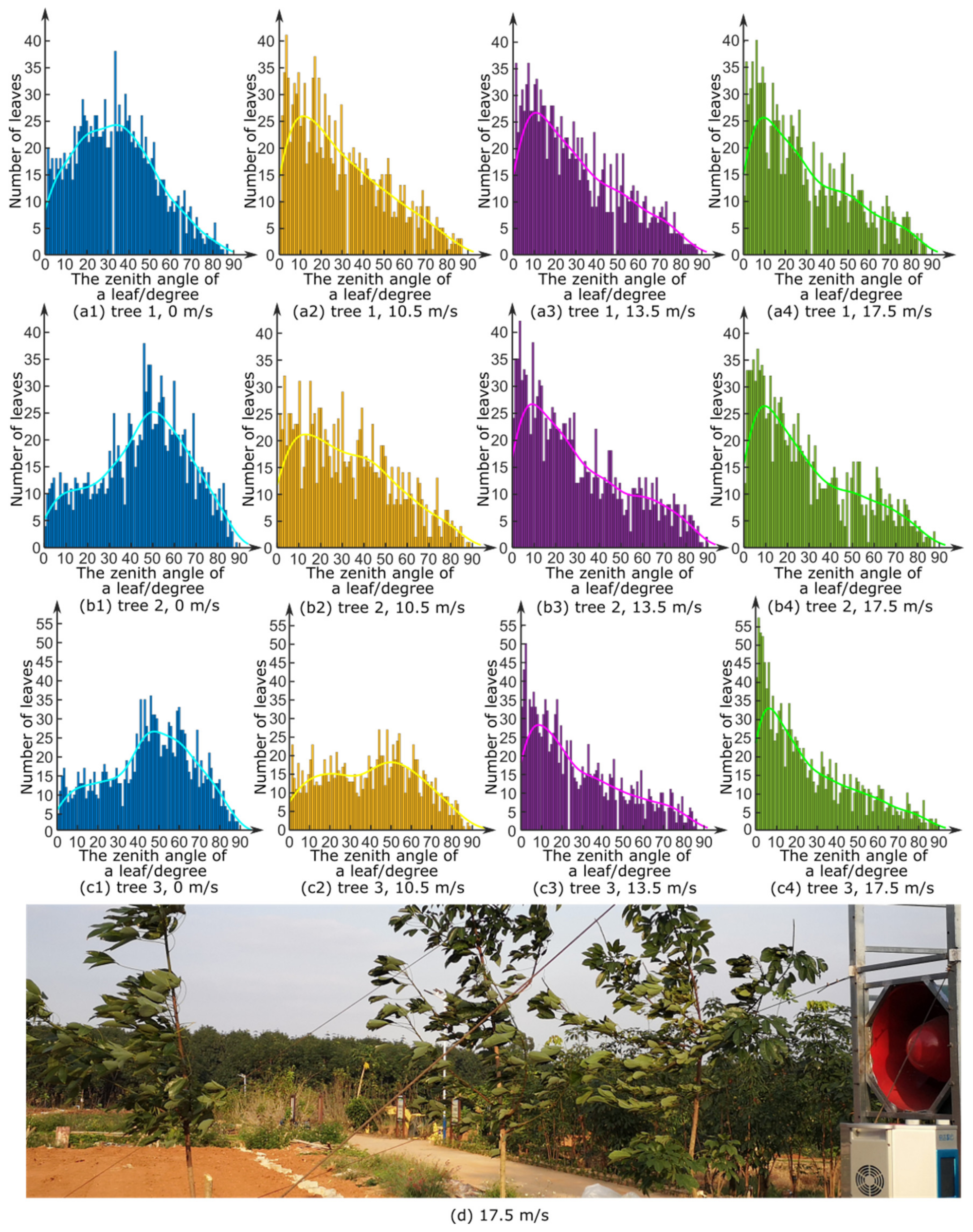
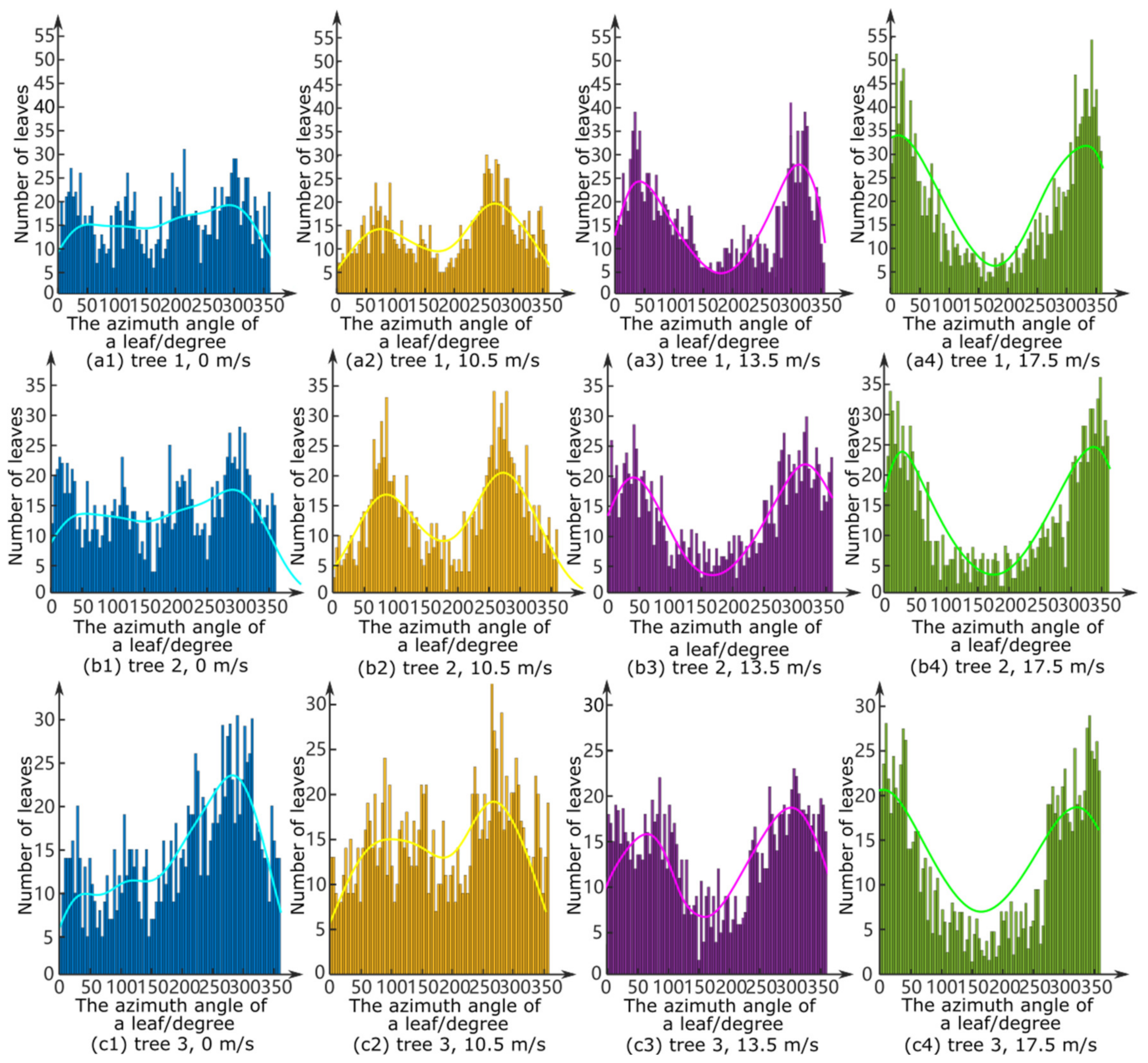
3.2. Leaf Azimuth and Zenith Angles of the Three Experimental Trees

In Section 3.1, we obtained the leaf distributions and branch skew variations of each tree under four different wind speeds using individual leaf segmentation. Here, these results were used to calculate the zenith and azimuth angles of all the leaves on each rubber tree under four different wind speeds based on the algorithm introduced in Section 2.3. We rendered the angular distributions of all the leaves on each rubber tree under the four distinct wind speeds and plotted them in histograms (Figure 7 and Figure 8), which vividly depict the trends of the zenith angle and the azimuthal distributions of all the leaves on each tree with the change in wind speed and the variation in the leaf positions on the three rubber trees.
As shown in Figure 7, the larger the wind speed that flowed through the experimental trees, the greater the number of leaf zenith angles on the experimental trees that tended to be 0°, which was as a result of the mechanical deformations of leaves and the elastic deformation of their petioles due to wind loadings. As the wind speed increased, the zenith angle histograms of each rubber tree gradually changed to exhibit unimodal distributions with the peak concentrated at 0°. Due to the effects of trees in reducing the wind speed, the first experimental tree, Tree 1, was subjected to the largest wind force among the experimental trees, which is why the zenith angles of the first experimental tree prematurely tended to cluster at the peak of 0°, whereas Trees 2 and 3 reached this trend in succession after the power of the forced draft fan was increased. After the zenith angle distribution reached an evident trend with the peak at 0°, the leaves became stable, i.e., the variation in the leaf zenith angle reached the maximum permissible tolerance, and thus, no significant change further occurred with an increase in the wind speed, as shown in Figure 7.
In addition, with the increase in the wind speed emitted by the forced draft fan, Figure 8 shows that the leaf azimuth angles of the rubber trees gradually spread on either side towards 0° and 360°, presenting a bimodal distribution. The azimuth angle distribution of the leaves on Tree 1 changed expeditiously since this tree (the tree closest to the forced draft fan) was subjected to stronger winds than the other two trees due to the ability of trees to block wind. Figure 7 presents the influence of the forced draft fan on the leaves of the rubber trees at a fan frequency of 60 Hz. The actual leaf zenith angles and leaf azimuth angles were consistent with the results calculated by our algorithm, confirming our conclusions.
Remarkably, some leaf azimuth angles and zenith angles were not clustered near the histogram peak (Figure 7 and Figure 8), which was because some leaves were affected by branch traction, and the branch nodes were firm enough to connect the leaves and the branches, causing branches to strongly bend and deform at bifurcations. Restricted by the power of the forced draft fan and the high stiffness of some petioles and branches, the wind speed was not always sufficiently strong to produce a large deformation of the branches and leaves; as a result, the leaves basically maintained their shape in equilibrium, and thus, the variations in the leaf azimuth angles and leaf zenith angles were not significant. Moreover, if the leaf clusters and branches are heavy, the effects of gravity cannot be ignored (given that leaves sag due to gravity), which may also have produced some leaf angle data away from the peak.
In addition, Figure 7 demonstrates that the variations in the distribution of leaf zenith angles for the tree farthest from the forced draft fan (Tree 3, Figure 7(c1,c2)) were less pronounced than those of the two trees nearer the forced draft fan (Trees 1 and 2, Figure 7(a1–b2)) during the initial stage of wind propagation produced by the forced draft fan, while the distribution of leaf zenith angles on Tree 3 varied abruptly during the second stage of wind propagation (Figure 7(c2,c3)). We suspect that the tree crown gaps of the two rubber trees closer to the forced draft fan were relatively small in the initial stage (i.e., the wind speed was low), significantly reducing the acceleration of the wind speed at the crown of Tree 3 (farthest from the forced draft fan), but these gaps later became considerably larger under the wind flow; this occurred because the gap fraction for the two rubber trees in front of the forced draft fan (Trees 1 and 2) became quite large and allowed stronger winds to pass, which linearly exacerbated (i.e., increased) the damage incurred by Tree 3 during the second stage.

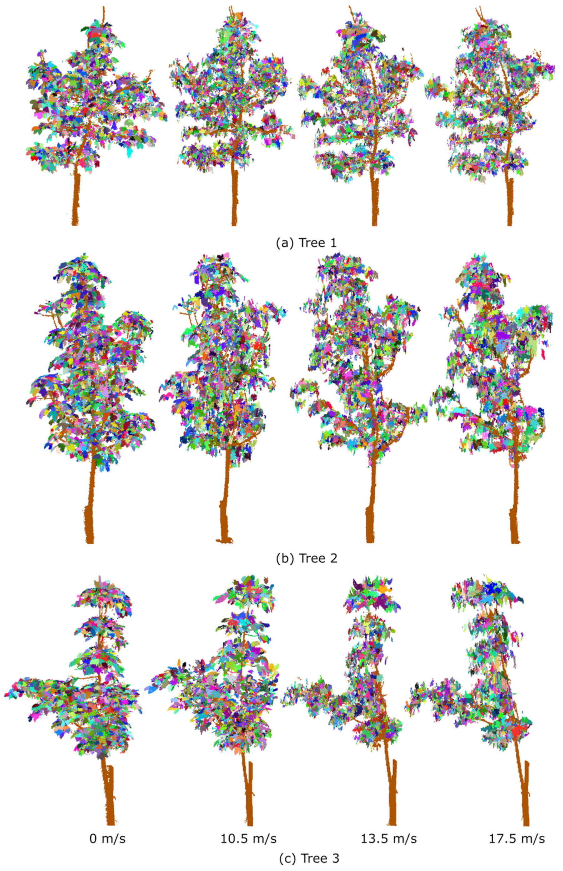
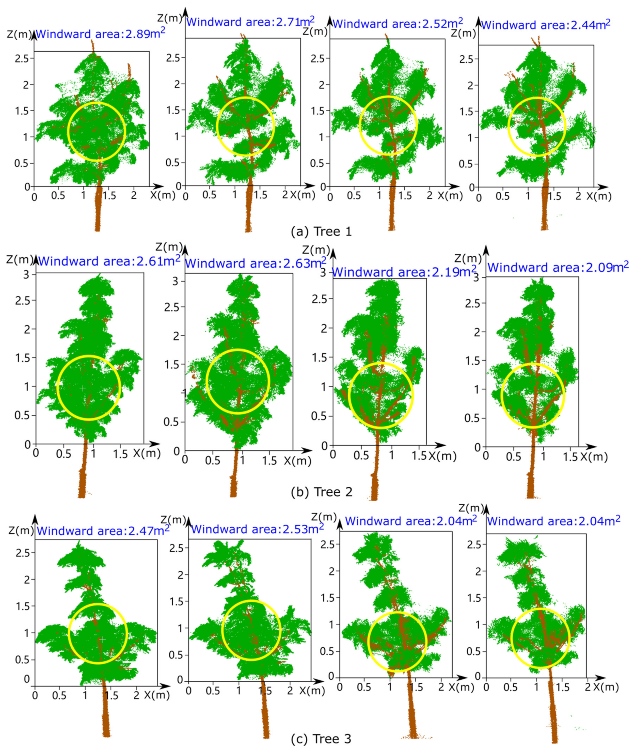
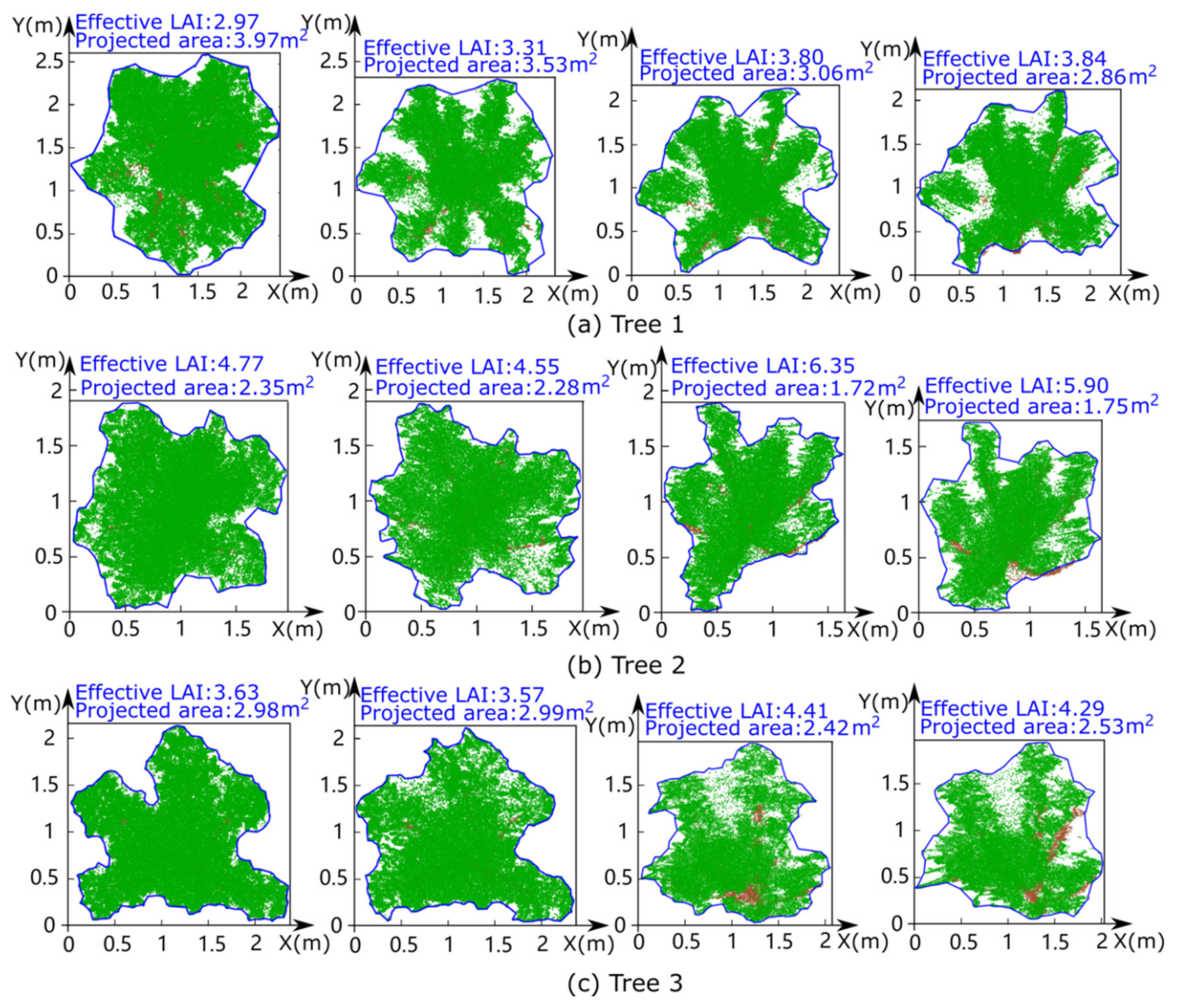
3.3. Changes in the Crown Morphologies of the Three Experimental Trees

The canopy windward areas and vertical projection areas of the three experimental trees under four different fan frequencies were calculated using the algorithm introduced in Section 2.3, and the results for the three trees (one per row) are shown in Figure 9 and Figure 10, respectively. Each row depicts four tree images representing the morphological variations of each experimental tree under different wind speeds, and each column presents three tree images representing the morphological variations of different trees under the same wind speed, with Tree 1, Tree 2, and Tree 3 in the first, second, and third rows, respectively. The windward area (Figure 9) and the vertical projection area and effective LAI (Figure 10) of each tree are clearly marked in blue font above each tree image, and the yellow circle in each image of Figure 9 is the position of the outlet of the forced draft fan relative to the experimental tree.
Although the calculated windward area and vertical projection area of a tree displayed minor fluctuations at different wind speeds, the overall declining trends of the windward area and vertical projection area with increasing wind speed are reflected in Figure 9 and Figure 10. These fluctuations may have been caused by some uncontrollable natural factors and errors in our measurement data or calculation methods. Since our experimental site was open-air, it was inevitable that natural wind blowing affected the experiment. Moreover, a dynamic structural swing of trees subject to wind loading occurred due to their own mechanical resilience and oscillation damping of the tree skeleton and foliage. Hence, the higher the experimental wind speed, the worse the quality of the LiDAR data obtained from two HS450 scanners, adding deviations to the subsequent processing of the data and producing noise. Furthermore, the noises also exacerbated the accuracy of individual leaf segmentation, resulting in certain errors in the leaf inclination and azimuth angle estimation. Since the wind was generated by a forced draft fan whose outlet shape was circular (the yellow circle marked in Figure 9), the deformation of the part of the rubber tree canopy that was closer to the axis of the outlet was more severe than the parts of the rubber tree crown farther from the outlet axis because the axis-adjacent part was subjected to a concentrated wind load. Figure 9 and Figure 10 show that the windward area and projection area generally decreased as the wind blew faster and that—similar to how the leaves clustered—the branches were skewed towards the north.
The overall decreasing trends in the windward area and the vertical projection area can generally be attributed to the porosity of the canopy structure. In other words, wind penetrated deep into the canopy when the trees were exposed to an air current, and this penetration substantially altered the crown characteristics of the rubber tree, including wind-induced extrusion and deformation of the tree crown.
The results obtained by integrating all the above work (i.e., the parameters of the three rubber trees at fan frequencies of 0 Hz, 30 Hz, 45 Hz, and 60 Hz) are summarised in Table 3 (Section 3.1), which also includes the wind speed in front of each tree, the distance from the centre of the tree crown to the forced draft fan, the tilt angle of the trunk, the tree crown volume, and the number of leaves obtained from each tree. Variations in the projection area and windward area can reflect the obvious deformation of the tree crown due to the wind load. As mentioned in Table 3, the centre of the crown of each tree gradually moved away from the forced draft fan with increasing wind speed, resulting in a temporary crown deflection caused by the wind load continuously striking the canopy. It is evident that the distance between the tree crown centre and the forced draft fan did not always increase dramatically with increasing wind speed, which may have been because of measurement errors during the experiment or because of the imprecise noise thresholds we established during individual leaf segmentation. Furthermore, the numbers of leaves obtained from the same tree under different wind speeds were not exactly the same (the bottom set of rows in Table 3) owing to the imprecise noise thresholds we established during individual leaf segmentation and the fact that some leaves with fragile petioles broke when the wind speed increased, resulting in a gradual decrease in the number of leaves obtained from the same tree. The projection area, windward area, and tree crown volume were gradually reduced, and the inclination angle of the trunk was obviously increased (clearly reflected in the left column of Figure 6) due to the increase in the wind speed produced by the forced draft fan.

4. Discussion

Three rubber trees were selected in our experiment to simulate different wind loads and thereby the wind damage to this tree species was explored. Some findings were also revealed by our work and are articulated below. First, our experiments confirmed that the changes in tree morphology became increasingly evident under stronger wind loads. Nevertheless, the third rubber tree exhibited fewer significant variations in its crucial parameters than the other two trees did because Trees 1 and 2 (closer to the fan than Tree 3) attenuated the wind speed when the porous media of the tree crowns obstructed the air flow. When the wind speed fluctuated within a range, the deformed tree crowns existed in a relatively stable state, causing the trees to acclimate to the continuous wind loading.
Second, some studies have shown that the effective LAI should decrease from before to after a storm [39,40], while our experiments showed that the effective LAI increased from a windless state to windy conditions. This phenomenon occurred because the periods both before and after a storm were windless states and the conditions were windy only when the storm occurred, which has not been examined by other researchers. Our experimental conditions were different from those used in previous studies, resulting in different but not contradictory experimental data. As shown in the photos of the scene, the tree defoliation phenomenon was inconspicuous, and the trunks of the trees were twisted but not fractured. Thus, the change in the total leaf area was not obvious, but the vertical projection area was reduced, leading to an increase in the effective LAI.
Finally, although the experimental trees did not break during our experiment, a threshold wind speed might certainly cause these trees to be uprooted or break their trunks. At the beginning of our experiment, the leaves on the experimental trees had randomly distributed zenith angles and azimuth angles, but these leaves gradually came to exhibit unimodal and bimodal distributions as the fan power grew. Moreover, we discovered that tree damage occurred in two stages. The first stage (emitted wind speeds from 0 to 10.5 m/s) was due to the two trees in front of the fan (Trees 1 and 2) effectively blocking the wind flow at a moderate speed, leading to only minor changes in the geometric morphology of the third tree (Tree 3) far from the fan. The second stage (emitted wind speeds from 10.5 to 17.5 m/s) characterised by a strong air current produced a linear increase in the gap between the canopies of Trees 1 and 2, which was conducive to allowing the passage of the air current through the crowns of Trees 1 and 2 and engendering significant variations in the zenith angles of the leaves on the third tree. Due to the wind loads compressing the tree canopies, the numerous leaves on the actual trees formed tightly packed clusters of foliage, and a great aerodynamic drag force interacted with the leaves. Hence, the morphologies of lateral branches supporting these clusters of foliage could be drastically changed (even break) under the influence of wind, potentially damaging woody tissue and affecting the normal physiological functions (photosynthesis, transpiration, and respiration) of branches and leaves.

4.1. Comparison with the Existing Methods

To date, many studies have been conducted to investigate the hazards of hurricane-induced damage to forests at relatively large scales and on smaller scales of forest plots and individual trees. Studies on “large-scale” features employed remote sensing data from before and after a storm to quantify the forest stand parameters and compared the data between the two periods to probe the variations in forest characteristics. However, the instability in precisely determining the hurricane direction, wind attack angle, tree species distribution within the forest, and topographic environment led to a limited capacity to further explore the associations of these factors with wind damage. Moreover, the changes in forest compositions caused by a hurricane cannot be effectively appraised, especially when performing an assessment using 2D images from satellites or manned aerial aircraft producing jitter and hampered by cloudy weather conditions that affects the data collection. Moreover, the top-down scanning mode obscures the acquired data from the intermediate layer of the forest [41]. Moreover, in a forest environment under drenching storm ravage, there is a great risk for forest data acquisition using the unmanned aerial vehicle-loaded LiDAR sensor.
In contrast, methods at the forest plot scale are based on computer simulations to establish a mathematical model using differential equations, transfer functions, and other means to portray the dynamic variations of trees under wind loads. However, the inadequate consideration of mathematical models (leading to inappropriate parameter assignments) can have a detrimental impact on the results; for example, the wind risk model could ignore the accurate time of the storm duration on a certain plot. Although many numerical formulas, e.g., the Navier–Stokes equations [42] and the turbulent kinetic energy equation [43], have been proposed to explain wind–forest interactions, the processes of a raging storm are highly stochastic, indeterminable, and unverifiable [44]. In addition, the final study results are also affected by the tree traits used as model inputs and the quantitative descriptions of plot-level details.
Alternatively, the individual tree scale emphasises branches or leaves as the objects of research to analyse the mechanical effects of wind loads on branches, leaf inclination variations, and vibration states using biological models and simulated experimental measurements. However, the interactions between leaves and branches are extremely complicated and hardly quantifiable; for instance, the physical interactions, namely, the frictional abrasion and cuttin, of branches and leaves [45], which can cause scarring on the epidermal tissues of trees, and the supporting effects among branches, trunks, and leaves require that individual tree-scale models be extended to a population model to more deeply explore the interference effects between individual components.
Here, we investigated the hazards of hurricane-induced damage to forests at the individual tree scale. Our experiment was carried out near a rubber plantation on Hainan Island, so the environmental conditions of the three rubber trees were exactly the same as those of trees in the natural environment, which allowed our experiment to take into account as many natural factors as possible and improved both the reliability and the accuracy of the experiment. Moreover, our LiDAR data were obtained from two HS450 scanners via a close-range symmetrical data collection and registration scheme. The tree crowns maintained a relatively constant state of compression under the continuous wind loading created by a large forced draft fan, thereby reducing the detrimental impact of insufficiently accurate data on the experimental results. In addition, with the support of a consistent experimental environment, accurate data, accurate experimental process, and other beneficial conditions, the experimental analysis was conducted on an individual tree scale based on our knowledge of aerodynamics, mechanics, forestry, and computer graphics, making the experimental results more persuasive.

4.2. The Restrictions of Our Experiment

Some problems encountered in our experiments necessitate better solutions.
Regarding the algorithms, the accuracy of the individual segmentation of leaves on the rubber trees under different wind loads was worse when the wind speed increased due to the unstable vibration of the leaves on the rubber trees exposed to strong winds. The leaves overlapped and became senescent during the experimental process due to the continuous tolerances of wind-induced leaf vibrations and suppression, yielding an over and under-segmentation phenomenon [46] during individual leaf segmentation, which introduced errors into the calculations of the azimuth and zenith angles. The strategy of adaptive parameter assignment synthetically combined with deep learning networks [47] should be considered for effectively removing noisy data points generated by vibrations and minimizing the error created by overlapping leaves to improve the accuracy of our algorithms as much as possible. Moreover, LiDAR data using a more advanced laser scanner [48] with more rapid and accurate data acquisition will improve the precision of the leaf-related parameter estimates to some extent [49].
Regarding the hardware configuration, real hurricanes have different vertical wind speed profiles, and their wind speeds vary with time. Realistic wind speed profiles during hurricanes generally appear logarithmic above the canopy, with an inflection point and strong wind shear at the canopy top, and decay exponentially within the crown layer [44]. First, our experiment of fan blowing lasted only 40 min, which is less than the duration of hurricanes in nature. Meanwhile, our experiment was hampered by the limitations on the outlet space of the forced draft fan, which was too small to cover the entire tree completely, causing the vertical wind speed profiles during our experiment to differ from those during hurricanes. Similarly, if we arranged 3 rows x 3 columns of trees to simulate the experiment, the strong airflow generated by the forced draft fan on the two rows of trees located on the edge of the row would not cause significant changes due to the fan calibre of 1.1 m producing an airflow centred around the fan outlet and the limitations of fan power (15 kw), and only the experimental data collected in the middle row aligned to the fan would be meaningful. In our later work, two more powerful fans will be purchased and assembled together to produce a vertically and spatially distributed wind field to further explore the mutual effects of forced airflow on a vast number of trees. Second, the intermittency of natural wind should be considered, especially when considering that high-frequency wind speed fluctuations occur during the peak of a windstorm. However, the wind speed in our experiment increased steadily without producing realistic wind speed fluctuations. An enhanced plan is to equip the system with an air resistance sensor for the forced fan, which allows the sensor to detect the signal of higher external air resistance and automatically reduce the frequency of the three-phase alternating current (AC) motor driving the fan, enabling the automatic adjustment of the rotational speed of the blades in the fan. Thus, natural wind simulation with speed regulation of the fan according to the change in external air resistance can be achieved to investigate the mechanism of wind-induced tree sway and the resonance effects between cyclic wind loading and the oscillatory tree response. Third, due to various limitations, such as the power supply of the fan, the danger inherent to hardware system assembly, i.e., collapse possibility of the overburdened lifting steel truss, vibrations, and the loud roar of the instruments during the experiment, the maximum wind speed in our experiment was approximately 20 m/s, which is much lower than the wind speed of a hurricane. However, obtaining measurements during a hurricane is dangerous, and it is difficult to protect sensitive laser scanner equipment in squally and rainy weather. Hence, for wind speeds ranging from 0 m/s to 20 m/s in a relatively safe environment, this study was sufficient to explore the effect of wind speed on trees, i.e., the variations in key parameters and phenotypic characteristics of trees with increasing wind speed, which provides heuristic guidance for assessments of the effects of a hurricane on the forest.
Regarding the experimental objects, since we transplanted experimental trees from a virgin forest to our experimental site, some factors inevitably affected our experiment. For instance, some secondary factors, such as phototropism, gravitropism, or growth history in the native areas of the experimental trees [50], affecting the morphologies of the experimental trees were ignored for simplicity. Meanwhile, only three rubber trees along with a self-assembled heavy instrument were used in our trial, resulting in a lack of replicates and the universality of the conclusions regarding the majestic power of nature (hurricane) acting on a larger rubber tree plantation. Similarly, trees in lush forests always have interlacing branches and overlapped tree crowns. Only three small trees were chosen with vacant spacing between each tree, resulting in a few crashes between neighbouring tree crowns without the reciprocal mechanical force propagation that leads to elasticity and damping among the interlocked forest canopy. Moreover, many variables affecting the extent of tree damage under wind loading are worth considering. For example, the smaller the toughness of the wood, the more likely are the trees to be damaged under wind loading. Additionally, because parts of the three rubber trees above the root of the main branch were installed on three fixed metal cubes, our experiments did not take into account the effect of soil type, which also merits further investigation.

5. Conclusions

In this study, a variance-based sensitivity analysis of the tree wind-risk model based on some rubber trees located in front of a designed forced draft fan that produces a strong air current was performed to quantify tree parameters. The results illustrated that windward area, vertical projection area of the tree crown, effective leaf area, leaf angle distribution, and bole inclined angle significantly impacted the variation in critical wind speeds created by the forced draft fan.
An attenuated wind blowing effect for trees far away from the fan manifested a weakened wind propagation strength by the fencing formed by trees near the fan, yielding an approximately 12.54% invariance in the tree properties under the same wind force loading for the tree distal to the fan compared with those closer to the fan. Our results demonstrated that terrestrial laser scanner cooperation with the built cost-effective wind fan can be used to monitor the severity of wind damage on target trees, both quantitatively and efficiently. This approach could be further optimised to make it more persuasive by synthetically considering other factors that may influence the experiment, such as the number of tree rows, a greater number of mounted sensors for the perception of tree trunk oscillation frequency or pressure in an environmental wind flow, and the use of other species of experimental trees. Meanwhile, another forced draft fan might be added to the steel lifting truss at greater heights with the generated wind field enshrouding the entire tree body, in tandem with advanced laser scanning devices for more accurate and faster data acquisition. As our understanding of the required research methodology improves, the proposed approach with reliability and scalability could become an essential tool for portraying a hazard map indicating the wind damage risk on various trees.

Author Contributions

Conceptualisation, B.Z. and X.Y.; methodology, B.Z., X.Y. and T.Y.; software, B.Z., X.Y. and T.Y.; validation, B.Z., T.Y., X.Y. and X.W.; investigation, T.Y. and X.W.; resources, X.W., F.A., H.Z. and T.Y.; data curation, X.W., F.A., L.Z. and T.Y.; writing—original draft preparation, B.Z. and X.Y.; writing—review and editing, J.S., X.Y., B.Z. and T.Y.; visualisation, B.Z.; supervision, T.Y. All authors have read and agreed to the published version of the manuscript.

Funding

This research was financially supported by the National Key R&D Program of China (No. 2019YFD1000500). This research was also funded by the National Natural Science Foundation of China (No. 31770591, No. 32071681), by the Opening Project Fund of the Key Laboratory of Biology and Genetic Resources of Rubber Tree, Ministry of Agriculture and Rural Affairs, China/State Key Laboratory Breeding Base of Cultivation and Physiology for Tropical Crops/Danzhou Investigation and Experiment Station of Tropical Crops, Ministry of Agriculture and Rural Affairs, P. R. China (No. RRI-KLOF202202), and by Student Practice Innovation and Training Program of Jiangsu Province, grant number 202110298001Z.

Institutional Review Board Statement

Not applicable.

Informed Consent Statement

Not applicable.

Data Availability Statement

The data supporting the reported results in this study has been uploaded to GitHub and made available at https://github.com/njyunting/windblowingforest1/, accessed on 8 August 2022.

Conflicts of Interest

The authors declare no conflict of interest.

References

  1. Mitchell, S.J. Wind as a natural disturbance agent in forests: A synthesis. Forestry 2013, 86, 147–157. [Google Scholar] [CrossRef]
  2. Radabaugh, K.R.; Moyer, R.P.; Chappel, A.R.; Dontis, E.E.; Russo, C.E.; Joyse, K.M.; Bownik, M.W.; Goeckner, A.H.; Khan, N.S. Mangrove Damage, Delayed Mortality, and Early Recovery Following Hurricane Irma at Two Landfall Sites in Southwest Florida, USA. Estuaries Coasts 2020, 43, 1104–1118. [Google Scholar] [CrossRef]
  3. Seidl, R.; Schelhaas, M.J.; Rammer, W.; Verkerk, P.J. Increasing forest disturbances in Europe and their impact on carbon storage. Nat. Clim. Chang. 2014, 4, 806–810. [Google Scholar] [CrossRef]
  4. Gardiner, B.; Berry, P.; Moulia, B. Review: Wind impacts on plant growth, mechanics and damage. Plant Sci. 2016, 245, 94–118. [Google Scholar] [CrossRef]
  5. Tang, C.; Yang, M.; Fang, Y.; Luo, Y.; Gao, S.; Xiao, X.; An, Z.; Zhou, B.; Zhang, B.; Tan, X.; et al. The rubber tree genome reveals new insights into rubber production and species adaptation. Nat. Plants 2016, 2, 16073. [Google Scholar] [CrossRef]
  6. Huang, J.; Pan, J.; Zhou, L.; Zheng, D.; Yuan, S.; Chen, J.; Li, J.; Gui, Q.; Lin, W. An improved double-row rubber (Hevea brasiliensis) plantation system increases land use efficiency by allowing intercropping with yam bean, common bean, soybean, peanut, and coffee: A 17-year case study on Hainan Island, China. J. Clean. Prod. 2020, 263, 121493. [Google Scholar] [CrossRef]
  7. Chen, B.; Cao, J.; Wang, J.; Wu, Z.; Tao, Z.; Chen, J.; Yang, C.; Xie, G. Estimation of rubber stand age in typhoon and chilling injury afflicted area with Landsat TM data: A case study in Hainan Island, China. For. Ecol. Manag. 2012, 274, 222–230. [Google Scholar] [CrossRef]
  8. Lappen, C.-L.; Schumacher, C. Scale interaction between typhoons and the North Pacific subtropical high and associated remote effects during the Baiu/Meiyu season. J. Geophys. Res. 2014, 119, 5157–5170. [Google Scholar] [CrossRef]
  9. Su, H.; Qian, C.; Gu, H.; Wang, Q. The Impact of Tropical Cyclones on China in 2016. Trop. Cyclone Res. Rev. 2016, 5, 1–11. [Google Scholar] [CrossRef]
  10. Tan, C.; Fang, W. Forest disturbance analysis with Landsat-8 OLI data related to a parametric wind field: A case study for Typhoon Rammasun (201409). Int. Arch. Photogramm. Remote Sens. Spat. Inf. Sci. ISPRS Arch. 2018, 42, 1629–1633. [Google Scholar] [CrossRef]
  11. Dupont, S.; Pivato, D.; Brunet, Y. Wind damage propagation in forests. Agric. For. Meteorol. 2015, 214–215, 243–251. [Google Scholar] [CrossRef]
  12. Yu, T.; Hu, C.; Xie, Y.; Liu, J.; Li, P. Mature pomegranate fruit detection and location combining improved F-PointNet with 3D point cloud clustering in orchard. Comput. Electron. Agric. 2022, 200, 107233. [Google Scholar] [CrossRef]
  13. Dolan, K.A.; Hurtt, G.C.; Chambers, J.Q.; Dubayah, R.O.; Frolking, S.; Masek, J.G. Using ICESat’s Geoscience Laser Altimeter System (GLAS) to assess large-scale forest disturbance caused by hurricane Katrina. Remote Sens. Environ. 2011, 115, 86–96. [Google Scholar] [CrossRef]
  14. Thom, D.; Seidl, R. Natural disturbance impacts on ecosystem services and biodiversity in temperate and boreal forests. Biol. Rev. Camb. Philos. Soc. 2016, 91, 760–781. [Google Scholar] [CrossRef]
  15. Gilman, E.F.; Masters, F.; Grabosky, J.C. Pruning affects tree movement in hurricane force wind. Arboric. Urban For. 2008, 34, 20–28. [Google Scholar] [CrossRef]
  16. Hayashi, M.; Saigusa, N.; Oguma, H.; Yamagata, Y.; Takao, G. Quantitative assessment of the impact of typhoon disturbance on a Japanese forest using satellite laser altimetry. Remote Sens. Environ. 2015, 156, 216–225. [Google Scholar] [CrossRef]
  17. Villamayor, B.M.R.; Rollon, R.N.; Samson, M.S.; Albano, G.M.G.; Primavera, J.H. Impact of Haiyan on Philippine mangroves: Implications to the fate of the widespread monospecific Rhizophora plantations against strong typhoons. Ocean Coast. Manag. 2016, 132, 1–14. [Google Scholar] [CrossRef]
  18. Rich, R.L.; Frelich, L.; Reich, P.B.; Bauer, M.E. Detecting wind disturbance severity and canopy heterogeneity in boreal forest by coupling high-spatial resolution satellite imagery and field data. Remote Sens. Environ. 2010, 114, 299–308. [Google Scholar] [CrossRef]
  19. Lagergren, F.; Jönsson, A.M.; Blennow, K.; Smith, B. Implementing storm damage in a dynamic vegetation model for regional applications in Sweden. Ecol. Modell. 2012, 247, 71–82. [Google Scholar] [CrossRef]
  20. Pivato, D.; Dupont, S.; Brunet, Y. A simple tree swaying model for forest motion in windstorm conditions. Trees Struct. Funct. 2014, 28, 281–293. [Google Scholar] [CrossRef]
  21. Schelhaas, M.J. The wind stability of different silvicultural systems for Douglas-fir in the Netherlands: A model-based approach. Forestry 2008, 81, 399–414. [Google Scholar] [CrossRef]
  22. Dupont, S.; Ikonen, V.P.; Väisänen, H.; Peltola, H. Predicting tree damage in fragmented landscapes using a wind risk model coupled with an airflow model. Can. J. For. Res. 2015, 45, 1065–1076. [Google Scholar] [CrossRef]
  23. Locatelli, T.; Tarantola, S.; Gardiner, B.; Patenaude, G. Variance-based sensitivity analysis of a wind risk model—Model behaviour and lessons for forest modelling. Environ. Model. Softw. 2017, 87, 84–109. [Google Scholar] [CrossRef]
  24. Gardiner, B.; Peltola, H.; Kellomäki, S. Comparison of two models for predicting the critical wind speeds required to damage coniferous trees. Ecol. Modell. 2000, 129, 1–23. [Google Scholar] [CrossRef]
  25. Watt, M.S.; Moore, J.R.; McKinlay, B. The influence of wind on branch characteristics of Pinus radiata. Trees Struct. Funct. 2005, 19, 58–65. [Google Scholar] [CrossRef]
  26. Chiba, Y. Modelling stem breakage caused by typhoons in plantation Cryptomeria japonica forests. For. Ecol. Manag. 2000, 135, 123–131. [Google Scholar] [CrossRef]
  27. Tadrist, L.; Saudreau, M.; de Langre, E. Wind and gravity mechanical effects on leaf inclination angles. J. Theor. Biol. 2014, 341, 9–16. [Google Scholar] [CrossRef]
  28. Zhu, Y.; Shao, C. The steady and vibrating statuses of tulip tree leaves in wind. Theor. Appl. Mech. Lett. 2017, 7, 30–34. [Google Scholar] [CrossRef]
  29. Dupont, S.; Défossez, P.; Bonnefond, J.M.; Irvine, M.R.; Garrigou, D. How stand tree motion impacts wind dynamics during windstorms. Agric. For. Meteorol. 2018, 262, 42–58. [Google Scholar] [CrossRef]
  30. Poh, H.J.; Chan, W.L.; Wise, D.J.; Lim, C.W.; Khoo, B.C.; Gobeawan, L.; Ge, Z.; Eng, Y.; Peng, J.X.; Raghavan, V.S.G.; et al. Wind load prediction on single tree with integrated approach of L-system fractal model, wind tunnel, and tree aerodynamic simulation. AIP Adv. 2020, 10, 075202. [Google Scholar] [CrossRef]
  31. Jackson, T.; Shenkin, A.; Wellpott, A.; Calders, K.; Origo, N.; Disney, M.; Burt, A.; Raumonen, P.; Gardiner, B.; Herold, M.; et al. Finite element analysis of trees in the wind based on terrestrial laser scanning data. Agric. For. Meteorol. 2019, 265, 137–144. [Google Scholar] [CrossRef]
  32. Rubol, S.; Ling, B.; Battiato, I. Universal scaling-law for flow resistance over canopies with complex morphology. Sci. Rep. 2018, 8, 4430. [Google Scholar] [CrossRef]
  33. Jian, Z.; Bo, L.; Mingyue, W. Study on windbreak performance of tree canopy by numerical simulation method. J. Comput. Multiph. Flows 2018, 10, 259–265. [Google Scholar] [CrossRef]
  34. Huang, Z.; Huang, X.; Fan, J.; Eichhorn, M.; An, F.; Chen, B.; Cao, L.; Zhu, Z.; Yun, T. Retrieval of aerodynamic parameters in rubber tree forests based on the computer simulation technique and terrestrial laser scanning data. Remote Sens. 2020, 12, 1318. [Google Scholar] [CrossRef]
  35. Yun, T.; An, F.; Li, W.; Sun, Y.; Cao, L.; Xue, L. A novel approach for retrieving tree leaf area from ground-based LiDAR. Remote Sens. 2016, 8, 942. [Google Scholar] [CrossRef]
  36. Xu, Q.; Cao, L.; Xue, L.; Chen, B.; An, F.; Yun, T. Extraction of leaf biophysical attributes based on a computer graphic-based algorithm using terrestrial laser scanning data. Remote Sens. 2019, 11, 15. [Google Scholar] [CrossRef]
  37. Xu, Y.; Hu, C.; Xie, Y. An improved space colonization algorithm with DBSCAN clustering for a single tree skeleton extraction. Int. J. Remote Sens. 2022, 43, 3692–3713. [Google Scholar] [CrossRef]
  38. Xu, S.; Wang, R.; Wang, H.; Yang, R. Plane Segmentation Based on the Optimal-Vector-Field in LiDAR Point Clouds. IEEE Trans. Pattern Anal. Mach. Intell. 2021, 43, 3991–4007. [Google Scholar] [CrossRef]
  39. Öztürk, M.; Bolat, İ. Pre- and post-windstorm leaf area index of Carpinus betulus trees in an urban forest patch. İstanb. Üniv. Orman Fak. Derg. 2016, 66, 513–523. [Google Scholar] [CrossRef]
  40. Chang, C.T.; Lee Shaner, P.J.; Wang, H.H.; Lin, T.C. Resilience of a subtropical rainforest to annual typhoon disturbance: Lessons from 25-year data of leaf area index. For. Ecol. Manag. 2020, 470–471, 118210. [Google Scholar] [CrossRef]
  41. Lu, K.; Xu, R.; Li, J.; Lv, Y.; Lin, H.; Liu, Y. A Vision-Based Detection and Spatial Localization Scheme for Forest Fire Inspection from UAV. Forests 2022, 13, 383. [Google Scholar] [CrossRef]
  42. Knaus, H.; Rautenberg, A.; Bange, J. Model comparison of two different non-hydrostatic formulations for the Navier-Stokes equations simulating wind flow in complex terrain. J. Wind Eng. Ind. Aerodyn. 2017, 169, 290–307. [Google Scholar] [CrossRef]
  43. Hiscox, A.L.; Rudnicki, M.; Miller, D.R. Understanding turbulent kinetic energy (TKE) stationarity within a forest canopy. Agric. For. Meteorol. 2015, 214–215, 124–133. [Google Scholar] [CrossRef]
  44. Dupont, S. A simple wind-tree interaction model predicting the probability of wind damage at stand level. Agric. For. Meteorol. 2016, 224, 49–63. [Google Scholar] [CrossRef]
  45. Cataldo, J.; Durañona, V.; Pienika, R.; Pais, P.; Gravina, A. Wind damage on citrus fruit study: Wind tunnel tests. J. Wind Eng. Ind. Aerodyn. 2013, 116, 1–6. [Google Scholar] [CrossRef]
  46. Nong, C.; Fan, X.; Wang, J. Semi-supervised Learning for Weed and Crop Segmentation Using UAV Imagery. Front. Plant Sci. 2022, 13, 927368. [Google Scholar] [CrossRef]
  47. Fan, X.; Luo, P.; Mu, Y.; Zhou, R.; Tjahjadi, T.; Ren, Y. Leaf image based plant disease identification using transfer learning and feature fusion. Comput. Electron. Agric. 2022, 196, 106892. [Google Scholar] [CrossRef]
  48. Li, Q.; Li, X.; Tong, Y.; Liu, X. Street Tree Crown Detection with Mobile Laser Scanning Data Using a Grid Index and Local Features. PFG J. Photogramm. Remote Sens. Geoinf. Sci. 2022, 90, 305–317. [Google Scholar] [CrossRef]
  49. Liu, X.; Li, Q.; Xu, Y.; Wei, X. Point Cloud Intensity Correction for 2D LiDAR Mobile Laser Scanning. Wirel. Commun. Mob. Comput. 2022, 2022, 3707985. [Google Scholar] [CrossRef]
  50. Lang, A.C.; Härdtle, W.; Bruelheide, H.; Geißler, C.; Nadrowski, K.; Schuldt, A.; Yu, M.; von Oheimb, G. Tree morphology responds to neighbourhood competition and slope in species-rich forests of subtropical China. For. Ecol. Manag. 2010, 260, 1708–1715. [Google Scholar] [CrossRef]
Figure 1. An overview of the workflow of the approach developed in the present study.
Forests 13 01298 g001
Figure 2. Location of the study area, Danzhou, Hainan Island, China. The left and middle images are remote sensing images from Google Earth, and the right image shows the rubber tree planation in the experimental site.
Forests 13 01298 g002
Figure 3. Photos showing the experimental site with three rubber trees arranged at a fixed interval in front of the forced draft fan. (ac) show the real photos of the built steel lifting truss loading the fan and the experimental setup. Red circles in (c) indicate co-registration targets for the multi-scan co-registration.
Forests 13 01298 g003
Figure 4. Photos (left) of the field experiment simulating the effects of a strong air current on trees under different wind speeds and point cloud data (right) after the wood–leaf classification under different wind speeds. The emitted wind speeds of the fan from (a1d2) are 0 m/s, 10.5 m/s, 13.5 m/s, and 17.5 m/s, respectively.
Forests 13 01298 g004
Figure 5. Leaf distribution for each rubber tree under four wind speeds obtained using an individual leaf segmentation algorithm, where brown represents the trunk and branches, and the extracted individual leaves are highlighted in different colours. (ac) correspond to Tree 1, Tree 2, and Tree 3, respectively. Each column of the figure from left to right represents the individual leaf segmentation results of the same tree under forced draft fan-emitted wind speeds of 0 m/s, 10.5 m/s, 13.5 m/s, and 17.5 m/s, respectively.
Forests 13 01298 g005
Figure 6. Tree crown volume changes and branch skew variations of the three rubber trees under four wind speeds, i.e., 0 m/s, 10.5 m/s, 13.5 m/s, and 17.5 m/s. (a1d1) show only the branch point clouds. (a2d2) show the results after calculating the tree crown volumes of the three rubber trees at four wind speeds with the alpha shape algorithm.
Forests 13 01298 g006
Figure 7. (a1c4) illustrate the distribution of the zenith angle for individual leaves of the three rubber trees under various wind loading at four speeds, i.e., 0 m/s, 10.5 m/s, 13.5 m/s, and 17.5 m/s, respectively. (d) is a photo showing the effect of the simulated wind speed on the rubber trees under a wind speed of 17.5 m/s.
Forests 13 01298 g007
Figure 8. (a1c4) illustrate the distribution of the azimuth angle for individual leaves of the three rubber trees under various wind loading at four speeds, i.e., 0 m/s, 10.5 m/s, 13.5 m/s, and 17.5 m/s, respectively.
Forests 13 01298 g008
Figure 9. The windward area of each rubber tree under various wind hazards. (ac) represent Tree 1 (closest to the fan), Tree 2 (the middle tree), and Tree 3 (farthest from the fan), respectively, and the yellow circle represents the corresponding position of the forced draft fan in the current view. The columns from left to right represent the variations of windward area corresponding to different wind velocities, i.e., 4.6 m/s, 10.5 m/s, 13.5 m/s, and 17.5 m/s, respectively.
Forests 13 01298 g009
Figure 10. The vertical projection area of each rubber tree crown under various wind hazards. (ac) represent Tree 1 (closest to the fan), Tree 2 (the middle tree), and Tree 3 (farthest from the fan), respectively, and the yellow circle represents the corresponding position of the forced draft fan in the current view. The columns from left to right represent the variations of windward area corresponding to different wind velocities, i.e., 4.6 m/s, 10.5 m/s, 13.5 m/s, and 17.5 m/s, respectively.
Forests 13 01298 g010
Table 1. Brief introduction to the existing methods for studying the damaging effects of wind on forests.
CategoryTypical CitationHighlightsRestrictions
Large scale[16]The experimental site was located on Hokkaido, Japan. Based on Geoscience Laser Altimeter System (GLAS) data, a statistical method relying on the empirical equations of three main parameters was used to establish a model to estimate the canopy height and discuss the impact of Typhoon Songda.Statistical methods that rely on empirical equations need equations that are specific to certain places and thus are difficult to serve as simple and practical direct methods. To improve the accuracy of the model, it would be necessary to classify the data, such as flat vs. steep ground. Second, due to the weak strength of laser signals, the data obtained after the leaves have fallen should be discarded.
[17]Using Google Earth satellite data from the central Philippines after Super Typhoon Haiyan, regression analyses were performed for forest age, mortality, and diameter at breast height (DBH), and a variance analysis was performed to assess significant differences. When the age exceeds a certain threshold, massive death can occur after a typhoon.Statistical analysis was carried out on the impact of a typhoon only on mangrove forests, and there is no feasible experimental scheme to predict and effectively mitigate the impacts of super typhoons.
[13]GLAS data from the Ice Cloud and Elevation Satellite (IceSat) before and after Hurricane Katrina in the south-eastern United States were used to calculate the mean canopy height (MCH), and the t test was used to verify the significance of the difference between the mean MCH before and after the storm. A gridded model was also established to estimate the height loss.The quantified scope and scale over which hurricane-induced damage occurred are greatly affected by the validity of the GLAS data, and the sampling within the grid was too low to reliably estimate height changes, so this method is limited to the evaluation of average canopy heights and needs assistance from other indicators.
[18]In northeastern Minnesota, the mean digital number (DN) values and standard deviations of all bands from IKONOS (a satellite with a high spatial resolution) were obtained by extracting spectral information from IKONOS images, and the normalised difference vegetation index (NDVI) was calculated. Texture algorithms and ERDAS Imagine texture functions were used to acquire texture features coupled with field survey data. Least squares regression analysis and multiple linear regression were combined to determine the model.The method used in this study required the modelling of satellite data in combination with field survey data, which are difficult to obtain in some areas. In addition, texture features may be compared only at a specific range of spatial resolutions, and it is difficult to unambiguously combine pixels with forest structures.
Forest plot scale[19]A dynamic vegetation model (i.e., LPJ-GUESS) was used in Sweden, and Swedish National Forest Inventory (SNFI) data from 2014 were used to initialise the model. Combined with the existing mechanisms and empirical models, a regional-scale wind damage simulation model with mechanical characteristics was established based on experience and mechanical knowledge that could accurately predict the distribution of wind damage at the regional level.Although the model of this study had outstanding effects at the regional level, it lacked certain effects at the forest stand level and lacked adequate explanatory ability. Second, the robustness of the model must be tested when it is applied to other areas with forest structures similar to those in Sweden. The model’s standard factors must also be recalibrated when new conditions arise.
[20]In this study, a simple tree swaying model was established by simplifying the tree as a cantilever beam. The model included the tree motion equation, damage condition, numerical method, and filament test, and the model was combined with the mechanical knowledge of disturbance and fracture conditions to simulate the damaging impact of a hurricane on the canopy of a forest.This is a simple model that reduces the tree to a uniformly distributed cylindrical cantilever. This model may work well for some trees (such as a maritime pine tree) but may be less effective for trees that do not have this characteristic shape (i.e., a large crown).
[21]For the different silvicultural systems for Douglas-fir (Pseudotsuga menziesii (Mirb.) Franco) in the Netherlands, a FORGEM-W model was established by combining the ForGEM model with a damage module following the HWIND model principle. The influence of wind on trees with variation in the height–diameter (h/d) ratio was evaluated by examining the h/d ratios of trees, and the wind damage of trees with a low h/d ratio was found to be relatively small.Since hurricanes have a finite duration, trees may adapt to the force of a hurricane, but this model does not take into account the adaptability of trees to wind. In addition, the forest cultivation system has a great influence on the tree parameters, and the wind damage module is sensitive to the anchoring parameters.
[22]In this study, the HWIND wind risk model and Aquilon airflow model were coupled and applied to evaluate heterogeneous landscapes. The Aquilon model adopted the k ε turbulence scheme, and the gust factor was deduced based on the probability distributions of wind speed and turbulent kinetic energy. The HWIND model alone and the coupled model were used for a comparative analysis.Coupling a wind risk model with an airflow model is bound to be complex and time-consuming; thus, the model cannot simply be applied to simulate forest wind damage similar to a wind risk model alone. Moreover, the gust factor and wind speed profile of HWIND have certain limitations, which engender differences between the gust factor and wind speed profile. The critical wind speeds (CWS) of HWIND and HWIND-Aquilon models are also different.
[23]The ForestGALES wind risk model (a model that can calculate the CWS for tree damage by using the stand characteristics) was used to perform a variance-based sensitivity analysis by using the GlobalSA (GSA) method (a generalization of the relevant factors of the Sobol method). It was found that the root depth and soil type had little effect on the output of the model.Tall trees in the data set used in the study were underrepresented. The simulated tree taper, independent of the stocking density, would affect the results of the model. Due to the high sensitivity, the input data should be as accurate as possible, and accurate sampling of tree and stand variables should be carried out when applying the ForestGALES model.
[24]The hybrid mechanistic wind risk model, ForestGALES, and a statistical logistic regression model were used to assess observed damage in a Scottish upland conifer forest following a major storm. Statistical analysis demonstrated that increasing tree height and local wind speed during the storm were the main factors associated with increased damage levels.Additional methods of assessing wind risk were waiting to be validated and meticulously compared. There were insufficient data in this study to conduct a formal statistical analysis of the interaction between age and species. Improvement is required in the representation of within-forest variability in individual tree characteristics and their level of wind exposure.
Individual tree scale[25]In the Wairarapa Region on the North Island of New Zealand, the branch diameter model was adopted to conduct a significance test combined with bidirectional ANOVA of the site and treatment effects. Furthermore, regression of the branch diameter was conducted to evaluate the influence of wind on branch characteristics.The model in this study is not sensitive to wind speed but is highly sensitive to other factors that affect branch diameter. Therefore, poor predictions will be obtained in exposed areas with high wind speeds, and more experiments are needed to confirm the conclusions of this approach.
[26]In Hita city, Ooita Prefecture, the Sawada model was used to simulate the effects of wind on tree trunks. The combined influence of forces (e.g., wind) and gravity on trees varies according to the shape of the branches, and four assumptions were made to simplify the analysis.Since certain defects (e.g., insect damage, wood decay) may occur in wood, the height of the stem break may occur at the location of the defect. In addition to the height of stem break, the model of this study assumes that the shape of the stem is conical, and other shapes (e.g., parabolic, exponential) have not been further studied.
[27]Using an idealised tree model and statistics to identify the role of tree geometry, a biomechanical leaf angle model was established under gravity or wind loading. The Cauchy number was defined to represent the blade deformation caused by wind, and the effect of leaf deformation on the leaf inclination angle distribution (LIAD) was discussed.Only the effects of gravity and wind are included in the biomechanical model, while many other factors (e.g., phototropism and gravitropism) that are known to affect LIAD are not taken into account in the model.
[28]Seventy-three tulip leaves with a normally distributed leaf area were tested for their suspension, windward, and leeward areas. The state of the blades was observed and recorded at different wind speeds, and the critical Reynolds number was derived to replace the critical wind speed. Probabilistic knowledge was leveraged to study the relationship between the critical Reynolds number and leaf phenotypic characteristics.In this study, only one-leaf tulips were discussed, and the aerodynamic difference between the suspension direction and the erect direction was ignored due to the characteristics of tulip leaves (high petiole rigidity), which could not be ignored for other leaves with low petiole stiffness.
[29]An unprecedented field experiment (TWIST) was conducted in a maritime pine forest in southwestern France, where three instrumented trees with biaxial inclinometers and a pneumatic mast with four ultrasonic anemometers were installed to measure and analyse wind dynamics and tree interactions during four non-destructive storms experienced at the experimental site.During the experiment, it was necessary to ensure that the trees would not crash into the pneumatic mast and its shrouds due to storm action, thus causing problems with the data collected in the TWIST experiment. Additionally, the edge storms in the experiment were not strong enough to cause the trees to resonate and enhance flow turbulence along themselves.
[30]A hybrid integrated method including L-system fractal tree generation, 3D printed wind tunnel modeling, and computational fluid dynamics (CFD) simulation methodology was proposed to measure wind tunnel particle image velocimetry and drag force, as well as Reynolds-Average Navier–Stokes simulation and Large Eddy Simulation for the CFD simulation testing the effect of wind on three tree species.This method has limitations on the actual size of the tree model and urban field measurement validation due to the tree slenderness representation and structural flexibility, the actual random wind direction, which possesses high complexity, and computational cost.
[31]A new approach combining terrestrial laser scanning (TLS) data and finite element analysis with accurate 3D geometry of a tree in a mechanical simulation was used for the appraisal of the wind damage on tree body. This simulation was used to predict the mechanical strains produced on the trunks of 21 trees in Wytham Woods, UK.The use of the approach was limited by local wind data, so it must be combined with wind flow modelling. Several uncertainties remain, such as the accuracy of the TLS data in representing the 3D tree architecture, the mechanical properties of roots, and the change in wind–tree interactions at high wind speeds.
Table 2. Detailed technical specifications of the forced draft fan and wood and leaf points of the three experimental rubber trees.
Fan ModelRadius (m)Length (m)Fixed Height (m)
HTF-I-(A)-11A0.551.105.70
Tree height (m)Crown width (E–W)/(S–N) (m)Clear bole height (m)Distance to the forced draft fan (m)
Tree 13.762.50/2.611.531.28
Tree 24.081.93/1.821.673.28
Tree 33.772.39/2.161.555.28
Fan frequency (Hz)03045
Emitted wind speed (m/s)010.513.5
Wood/leaf points in Tree 127,426/222,08123,820/163,40120,663/151,202
Wood/leaf points in Tree 224,544/265,92824,952/175,17426,040/151,910
Wood/leaf points in Tree 333,781/314,89718,686/182,99925,548/122,061
Table 3. Variations in tree phenotypic parameters under the influence of different strong air currents.
Fan Frequency(I) 0 Hz(II) 30 Hz(III) 45 Hz(IV) 60 Hz
The wind speed in front of the tree (m/s)/Distance between the tree crown centre and the fan (m)
Tree 14.60/1.6710.5/1.9913.50/2.1617.50/2.29
Tree 21.80/3.694.80/3.679.10/4.0210.50/3.97
Tree 30/6.172.40/6.145.24/6.606.36/6.67
Projection area (m2)/Windward area (m2)/effective LAI
Tree 13.97/2.89/2.973.53/2.71/3.313.06/2.52/3.802.86/2.44/3.84
Tree 22.35/2.61/4.772.28/2.63/4.551.72/2.19/6.351.75/2.09/5.90
Tree 32.98/2.48/3.632.99/2.53/3.572.42/2.04/4.412.53/2.04/4.29
Tilt angle of the trunk * (°)/Crown volume (m3)
Tree 1−12.32/4.15−5.59/3.940.77/3.601.78/3.42
Tree 2−1.12/2.992.33/2.904.11/2.197.48/2.09
Tree 31.43/2.783.25/3.048.63/2.1810.19/2.34
Number of leaves obtained from the tree
Tree 11369135213451273
Tree 21355125813191253
Tree 31368134913471373
* The tilted angles (measured clockwise) traverse from the bole expansion direction to the zenith (vertical line); a negative sign indicates a counterclockwise rotation.
Publisher’s Note: MDPI stays neutral with regard to jurisdictional claims in published maps and institutional affiliations.

