
The Mechanical Properties of Wood-Based Grid Sandwich Structures


1
Key Laboratory of Heilongjiang Underground Engineering Technology, Harbin University, Harbin 150086, China
2
Laboratory of Bio-Based Material Science & Technology of Ministry of Education, College of Mechanical and Electrical Engineering, Northeast Forestry University, Harbin 150040, China
*
Author to whom correspondence should be addressed.
Forests 2022, 13(6), 877; https://doi.org/10.3390/f13060877
Submission received: 21 May 2022
/
Accepted: 30 May 2022
/
Published: 3 June 2022
(This article belongs to the Section Wood Science and Forest Products)
Abstract
:In order to reduce the weight of the panels used in buildings and minimize the use of wood, it is of great practical significance to study the mechanical properties of wood-based sandwich structures for adaptation to modern wood-structured buildings. In this paper, a wood-based pyramid structure specimen with large interconnection space was designed and prepared first. Based on the results of the flat compression, in order to strengthen the core layer of the sandwich structure, an interlocking grid structure can be used. The mechanical properties of two kinds of structure specimens, including bearing capacity, compressive strength, specific strength, load–mass ratio, safety factor distribution, and specific energy absorption, were studied by means of experimental test, theoretical analysis, and finite element analysis. It was concluded that the apparent density of the two structures was lower than that of the materials of which they were composed. However, the overall flat compressive strength of the two structures was higher than that of their constituent materials, which were high-strength materials in the field of natural materials. The mechanical properties of the interlocking grid structures were better than those of the pyramid structures. Based on the criterion of cell structure stability, it can be concluded that the wood-based pyramid structure was a flexural-dominant structure, and the interlocking grid structure was a tensile-dominant structure. The results show that the core layer design plays an important role in the mechanical properties and failure modes of wood-based sandwich structures.
1. Introduction
Sandwich structures have been successfully used in the aerospace industry, and in marine, mechanical, and civil engineering for many years due to their high strength, high stiffness, and high mass–load ratio [1,2]. The application of sandwich structures in building structures can reduce the consumption of nonrenewable raw materials. Most building materials are sourced from nonrenewable, natural mineral raw materials and some are sourced from industrial solid waste. Compared with automobiles, trains, airplanes, and other industries, the construction industry consumes more materials [3,4]. The construction materials mainly include concrete, steel, and wood. Building materials account for 23% of global primary energy consumption [5], consuming nearly 60 billion tons of materials annually [6], which leads to the consumption of more nonrenewable raw materials [7]. The use of wood-based materials can compensate for the scarcity of raw wood resources and alleviate the problem of the poorer quality of wood products from less mature trees [8]. The sandwich structure can mix two or more materials with specific geometric shapes and proportions, giving it new material properties [9]. The sandwich structure is composed of two flat surfaces with thick cores in the middle. The flat surfaces are made from upper and lower panels, and the core structure in the middle can take many forms. At present, the core layer design of sandwich structures mostly adopts the structural form of multi-cell solids, and can effectively expand the properties and application range of engineering materials [10].
The core design forms of common multi-cell solid structures mainly include honeycomb, foam, lattice, ripple, and various bionic structures [11,12]. This multi-cell solid structure can form several discrete and continuous structures with large interconnection space. By placing sound-absorbing, thermal insulation, and electromagnetic shielding materials in the interconnection space, an integrated solution for structural material production, manufacturing, and function can be formed [13,14].
Wood itself is a cell-structured material, which widely exists in nature. The application of wood-based materials in engineering design makes functional materials become porous solid materials, with cell structures both macroscopically and microscopically. Jin et al. used a wood composite material and birch to prepare a two-dimensional lattice truss sandwich structure by slotting and bonding. The out-of-plane compression and bending of this structure have good energy absorption capacity, but the stress degumming at the panel and core of the structure seriously affects the bearing capacity of the structure [15]. Li et al. made a composite two-dimensional lattice structure with a wood–plastic composite as the panel and glass-fiber-reinforced plastic as the core. According to its stress characteristics and failure type, reinforcing hoops were made at both ends of the core to increase the bearing capacity of the structure [16]. Li et al. also prepared a photosensitive resin-based 2D lattice structure with a variable cross-section core by 3D printing technology, which effectively solved the problems of great difficulty and poor accuracy when using conventional methods. They accurately concluded that when the two-dimensional lattice sandwich structure bears a plane compression load, both ends of the core bear large bending moment and axial force, and the middle position of the core only bears axial force [17]. Qin et al. made a wood-based 2D straight-column lattice truss sandwich structure with oriented strand boards (OSBs) and Betula; they tested the bearing capacity, equivalent compressive strength, and elastic modulus (MOE) of the structure through an out-of-plane compression experiment, and thickened the panel to increase the compressive strength of the structure. The results showed that the out-of-plane compressive ultimate strength of the wood-based 2D straight-column lattice truss sandwich structure had a linear relationship with the relative density of the core [18]. Zheng et al. used WPC (wood–plastic composites) and OSBs (oriented strand boards) as the panel, and used GFRP (glass-fiber-reinforced plastic) as the cores to prepare X and double X lattice sandwich structures. The mechanical properties and structural failure forms of the two structures were studied, and it was concluded that the structural form had high specific strength and modulus [19,20,21]. Yang et al. prepared a pyramidal sandwich structure by using Larch Sawn timber and birch as raw materials. According to the mechanical properties and failure forms of the structure, the compression strength of the structure increased by adopting the method of panel reinforcement [22,23,24]. Hao et al. explored the compression behavior of an ecofriendly natural-fiber-based isogrid lattice cylinder made of pineapple leaf fibers and phenol formaldehyde resin matrix. The results indicated that the number of equal divisions of the circumference was the main influence factor affecting the bearing capacity of the structure [25]. Jerzyi et al. prepared a sandwich structure with a face sheet made of high-density fiberboard and high-pressure laminate, and the auxetic lattice core was made by 3D printing using LayWood biocomposite filament to study its compression and low-speed impact properties. Experimental studies indicated that the core’s auxetic property (i.e., showing negative Poisson’s ratio) was observed within the planes parallel to the facings, and the structure had high compressive strength and energy absorption capacity [26]. Hao Jingxin et al. studied a sandwich structure with panels made from medium-density fiberboard (MDF) and plywood material (PLY), and the core layer used the traditional hexagonal honeycomb and taiji honeycomb structure. Experimental and analytical methods were used to study the compression behavior and failure mechanism of a novel taiji honeycomb wood-based sandwich structure. The results showed that the compressive strength and modulus of the taiji honeycomb composite significantly improved compared with the traditional hexagonal honeycomb structure. The characteristics of the core material used determine the strength of an entire structure [27]. Pelinski et al. studied a sandwich structure with panel materials made from plywood, high-density fiberboard, and cardboard, and the core was built with WoodEpox®, based on epoxy resin, with a lignin–cellulose mass as filler. The results showed that the sandwich structure with the auxetic core significantly reduced the dissipated energy [28].
Most of the above studies experimented with one type of structure, and the effects of different panel or core materials on the bearing capacity of the structure were analyzed and compared; if two structural forms were studied, most of them strengthened the panel or the core on the basis of the original structure, and few comparative studies with the same size and different structures have been carried out at the same time. Therefore, in this paper, we assessed wood-based sandwich structures with the same panel size and different core structures.
An outline of this study follows. Firstly, the mechanical properties of birch, larch, WPC, and OSB were studied by a universal mechanical testing machine. Secondly, the pyramid sandwich structure specimens were prepared with larch, WPC, and OSB as panels, with birch as the core material. Thirdly, the flat compression test was carried out on the pyramid structure specimen. According to the failure form of the core layer, the interlocking grid structure reinforced by the core layer was proposed, and the theoretical analysis and finite element analysis were carried out for the two structural forms. Finally, the mechanical properties of the two structures were comprehensively evaluated by bearing capacity, equivalent compressive strength, specific strength, mass–load ratio, and specific energy absorption.
2. Materials and Methods
2.1. Pyramid Structure Design
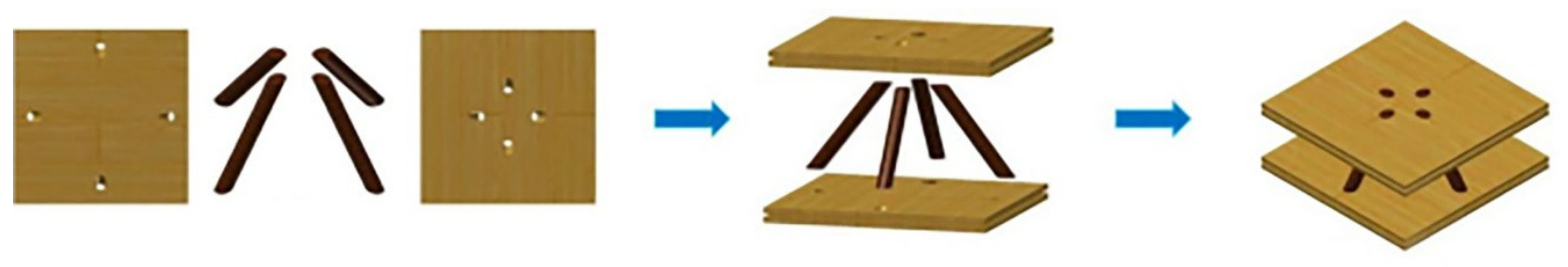
The wood-based pyramid sandwich structure is shown in Figure 1.
The panels of the pyramid structure were square. The relative density of the sandwich structure was the ratio of the core layer density to the solid material density of the sandwich structure.
The relative density of pyramid sandwich structure can be defined as:
where is the diameter of the core, is the length of the core and is the width of the cell panel, [29]. is the angle between the core and the lower panel.
A compression test was conducted on the pyramid structure specimens, and the structural parameters used for the specimens are shown in Table 1.
2.2. Specimen Preparation
3. Experiments
3.1. Mechanical Properties of Raw Materials
The direction of the board parallel to the direction of the surface shavings is the major axis of the OSB. The direction of the board vertical to the direction of the surface shavings is the minor axis of the OSB. It has lower mechanical properties than the major axis. OSBs with 0.61 g/cm3 density were tested in the major axis and the minor axis compression to determine the relevant Young’s modulus and compressive strength, in accordance with Zheng et al. [20].
The grain direction of the plywood remains the same for the length and direction of the finished board, this is called the longitudinal of plywood. The specimens were taken along the length and width directions of the plywood, respectively, and the longitudinal and transverse static bending strength MOR and elastic modulus MOE of the specimens were measured. The compressive strength of birch plywood along the longitudinal and transverse were taken from Cheng [24].
WPC (wood flour content: 60% and mixed with recycled high-density polyethylene plastic) data were produced at the Biomass Composite Engineering Research Center of Northeast Forestry University (Harbin, China). The basic density, ρ, compressive strength, and compressive modulus, were taken from Li et al. [16].
The compressive properties of the Larch finger-jointed lumber were tested according to GB 11916-89 (test methods for physical and mechanical properties of finger-jointed lumber). The compressive strengths of larch finger wood along the grain and modulus were 50.30 MPa and 26.68 GPa, respectively.
Birch rods are one of the common assembly and connection accessories for modern furniture. They are shaped as a round rod, and are generally made of wood. There are many forms on the surface of the rod, such as smooth surface, straight grain, spiral pattern, and reticulated pattern, etc.; for rods with the grain on the surface, because the glue forms dense glue nails after curing in the groove, the bonding effect is larger, and the connection strength for rods with a spiral pattern is generally better. Therefore, mostly, rods with spiral patterns were selected in this test. Birch rods were tested and optimally chosen using the method described by Jin et al. [15].
Physical and mechanical properties of the raw materials tested are listed in Table 2.
3.2. Flat Pressure Test
According to the ASTM C365-16 standard of compressive strength and compressive modulus, the pyramid structure specimens were tested at room temperature with a displacement rate of 1 mm/min by using a universal mechanical testing machine (model wdw-50, Kexin Test Instrument Co., Ltd., Changchun, China).
The failure modes of the wood-based pyramid structure specimens are shown in Figure 4. The failure mode of the structure with the combination of WPC + Birch mainly manifested in the splitting of the core and the fracture of the root at the contact between the panel and the core. The failure mode of the structure with the combination of OSB + Birch mainly manifested in the delamination of the OSB panel and the bending deformation of core. The failure mode of the structure with the combination of Larch + Birch mainly manifested in the cracking of the panel and the fracture of the core at the root.
The failure mode of the pyramid structure specimens under flat compression was mainly the failure of the core. The main reason is that the core is the main force-bearing body of the structure. The effective area of the contact between the core and the panel is very small, but the stress is very large. If the effective contact area between the core and the panel can be increased to reduce the stress, then the core part of the sandwich structure is strengthened, and the bearing capacity of the sandwich structure will be improved. Therefore, a core-reinforced interlocking grid structure is proposed.
3.3. Interlocking Grid Structure
The interlocking grid structure is shown in Figure 5.
The relative density of the interlocked grid structure can be defined as:
where h is the height of the bearing plate in the structure, and tf is the thickness of the bearing plate (the thickness of the bearing plate is the same as that of the panel).
Compression test was carried out on the interlocking grid structure specimens, and the structural parameters of the specimens used for testing are shown in Table 3.
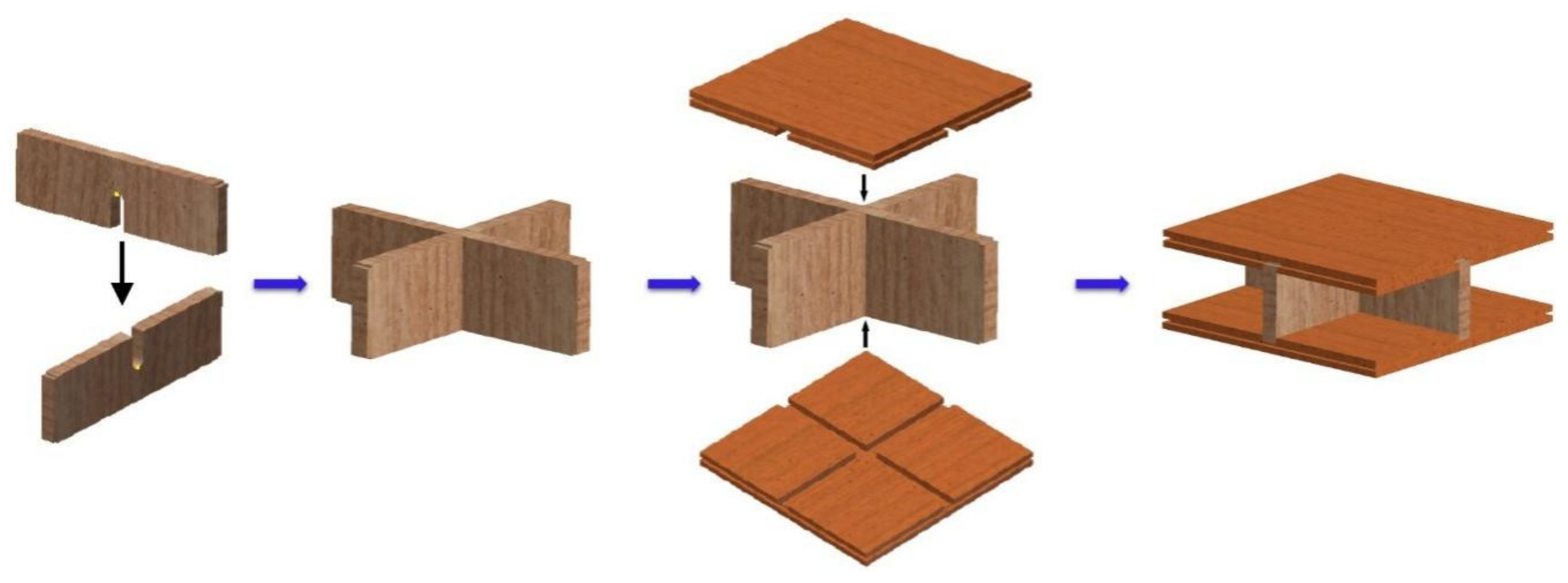
The fabrication of interlocking grid structure is shown in Figure 6. First, we milled the bearing plate and panel according to the design size. Secondly, we installed the bearing plates crosswise, and the two bearing plates were perpendicular to each other. Third, we applied the adhesive to the groove of the panel and the upper and lower edges of the bearing plate. Fourth, we inserted the bearing plate into the groove of the panel. Finally, we applied the appropriate pressure to the interlocking grid structure specimen with flat pliers. After 72 h, we removed the specimen and completed the fabrication of the specimen. The interlocking grid structure specimen is shown in Figure 7.
Compressive strength is an important mechanical property index of material structures, which represents the ability of a material structure to resist external force damage. The specific formula used to calculate the compressive strength can be defined as:
where is the maximum compression load and is the length of the specimen.
The formula used to calculate the compression modulus can be defined as:
where is the load increment of the linear elastic part of the compression curve, and is the deformation of the specimen.
Specific strength is the strength of a material divided by its apparent density. The specific strength can be defined as:
where is the apparent density of the specimen structure.
The load–mass ratio can be defined as:
where is the load mass ratio, and is the mass of the specimen.
The failure mode of interlocking grid structure specimens is shown in Figure 8. The failure mode of the structure is mainly the failure of the bearing plate. The material of the bearing plate is finger-jointed larch, and the structural failure mainly manifested as fracture at finger-jointed part of the bearing plate, while the grain splitting occurred at the non-finger-jointed part. Due to the different panel materials of the three specimens, the failure modes are different. The “Larch” panel was broken at the contact, the “Plywood” panel was layered at the contact, and the “OSB” panel was not damaged.
4. Results and Discussion
4.1. Structural Failure Process
The load–displacement curves of wood-based pyramid sandwich structure and wood-based interlocking grid structure are shown in Figure 9, which presents the load–displacement curves of six kinds of combined specimens of these two structures. The curves can be roughly divided into three stages: elastic stage, yield stage, and decline stage after peak load. In the elastic phase, the curve rises steeply, which can be approximated as a straight line, and begins to decline after reaching its peak. It can be observed from Figure 9a–f that all structures with bearing capacity lower than 16 kN are pyramid structures, and all structures with bearing capacity greater than 70 kN are interlocked grid structures. Displacements greater than 12 mm are pyramid structures, and displacements less than 12 mm are interlocking grid structures. In the elastic stage, the curve linearity results of the Larch + Birch composite specimen and the Larch + Larch composite specimen were not as good as those of the other four composite specimens. The reason for this phenomenon is that the materials used in these two composite specimens were solid wood and anisotropic materials. The load-bearing capacity of anisotropic materials in each direction is different. However, the materials used in the panels of the other four composite specimens all belong to wood-based composite materials, and the anisotropy of their raw materials was minimized in the process of production and processing [30]. The curves of the two specimens with OSB as the panel were steep and had good linearity in the elastic stage, which was determined by the characteristics of the OSB material itself. The wood shavings of OSB are arranged longitudinally on the upper and lower surfaces, and the middle core layer is arranged transversely. This crisscross means that OSB is stable and cannot be deformed when affected by the external environment. This process of reconstituting wood texture structure eliminates the anisotropy of wood, and its longitudinal bending strength is much greater than the transverse bending strength.
The load–displacement curve of the Larch + Birch composite specimen is shown in Figure 9a. In the elastic stage, the curve rose continuously with the increase in load, showing an approximate linearity. When the ultimate load was reached, the core showed bending deformation, and the root broke at the intersection of the panel and the core. With the increase in structural deformation, the panel of the specimen showed cracking.
The load–displacement curve of the WPC + Birch composite specimen is shown in Figure 9b. In the elastic stage, with the increasing load, the compressed deformation of the specimen gradually increased until the maximum load was reached. At this time, the core of the structure began to show damage. With the increasing displacement, the bearing capacity of the structure began to decrease until the core was sheared and fractured at the root, and the bearing capacity of the specimen structure decreased rapidly. The overall smoothness of the curve is due to the fact that the strength of the panel was greater than that of the core, and the panel was not damaged during the compression test.
The load–displacement curve of the OSB + Birch composite specimen is shown in Figure 9c. In the elastic stage, the curve increased steeply with the increase in load, presenting a good linear state. When the ultimate load was reached, the core was bent and deformed. In the yield stage, after a continuous period of displacement, the bearing capacity of the specimen decreased slowly with the continuous increase in structural deformation, and the layered failure of the OSB panel appeared.
The load–displacement curve of the Larch + Larch composite specimen is shown in Figure 9d. In the elastic stage, when the displacement of the curve was 1.5~7 mm, the curve showed good linearity. With the increase in load, the bearing plate in the core layer broke at the finger joint. When the limit load was reached, the panel split at the contact part between the panel and the bearing plate.
The load–displacement curve of the Plywood + Larch composite specimen is shown in Figure 9e. In the elastic stage, the curve had good linearity. With the increase in load, the bearing plate in the core layer split at the finger joint, and the further away from the center, the greater the degree of edge splitting. When reaching the limit load, the delamination failure occurred in the part of the panel in contact with the bearing plate.
The load–displacement curve of the OSB + Larch composite specimen is shown in Figure 9f. In the elastic stage, the curve slope was large and showed good linearity. With the increase in load, the bearing plate in the core layer split and broke at the finger joint, and the edge splits became clearer and broke away from the center. During the loading process of the specimen, the panel was not obviously damaged.
The core layer of the test piece of the pyramid structure comprised round rods, and the cross-section of a rod is small, so that the contact area between the core layer and the panel is also very small. This results in a concentration of stress for the structure under external load, meaning that structure is easily damaged. The interlocking grid structure can increase the contact area between the core layer and the panel and reduce the stress at the contact between the core layer and the panel. Additionally, it is a structural form that is convenient for processing and installation.
Compared with the pyramid structure specimen, the contact area between the core layer and the panel of the interlocking grid structure specimen increases a lot, and there is no concentration of stress when bearing an external load. The interlocking grid structure can effectively solve the problems caused by the inaccurate positioning, low machining accuracy, and large errors in the assembly process of pyramid structures in the manufacturing process. The bearing capacity of the interlocking grid structure was much higher than that of the pyramid structure specimen.
4.2. Compression Performance
The performance comparison between the pyramid structure specimens and the interlocking grid structure specimens under flat compression is shown in Figure 10. It can be observed from Figure 10a–d that the values of the pyramid structure specimens were small, and the values of the interlocking grid structure specimens were large. It was concluded that the performance of interlocking grid structure specimen was better than that of the pyramid structure specimens. The bearing capacity and compressive strength of the interlocking grid structure specimens were much higher than those of the pyramid structure specimens. In the pyramid structure specimens, the bearing capacity, compressive strength, and density of the WPC + Birch composite specimens were higher than those of the other two composite specimens. In the interlocking grid structure specimens, the bearing capacity and compressive strength of the OSB + Larch composite specimens were higher than the other two composite specimens, but its density value was not the largest.
The mass–load ratios of the interlocking grid structure specimens were higher than those of the pyramid structure specimens. In the pyramid structure specimens, the density values of the WPC + Birch composite specimens was the largest, but the specific strength value and mass–load ratios were the smallest. The density value, specific strength value, and the mass–load ratio of the Larch + Birch composite specimens and the OSB + Birch composite specimens were similar.
Comparing the bearing capacity, compressive strength, specific strength, and mass–load ratio of the two structural specimens, it can be concluded that, under the condition of the same structure and the same cell volume, the performance parameters of the pyramid structure are similar, and the performance parameters of the interlocking grid structure are quite different. Therefore, changing the core structure can effectively improve the bearing performance of the sandwich structure.
4.3. Theoretical Analysis
4.3.1. Pyramid Structure Analysis
In the pyramid structure, it was assumed that the connection between the cores and the panel was a fixed connection. In the flat compression state, the force on the pyramid structure mainly acts on four cores, and each core bears the vertically downward load force, F. The force analysis of the core is shown in Figure 11.
The axial force on the core is defined as:
where S is sectional area of the core, is the displacement of the structure in the Z direction under the action of the force F, is the reduction in the length under the action of the force F, l is the core length, d is the core diameter, and is the angle between the core and the direction.
The shear force on the core is defined as:
where I is the moment of inertia of the core section, .
The bending moment of the core is defined as:
where X is the distance between shear force and action point, .
Therefore, the Z-direction resultant force on the member can be expressed as:
Equivalent compressive stress of structure is defined as:
Then, the strain can be expressed as:
The cell equivalent flattening modulus can be expressed as:
The axial stress can be expressed as:
The maximum shear stress can be expressed as:
The bending moment stress can be expressed as:
Under the action of external load F, the stresses generated on the core are , and . According to the stress state of the core, the stress on the upper end of the core is − , the stress on the lower end is + , and the maximum shear stress that the neutral axis of the core can bear is . Therefore, as shown in Figure 11, the dangerous point of the core is located the area where point A. The failure position of the pyramid structure obtained by theoretical analysis is consistent with that obtained by experimental test.
4.3.2. Interlocking Grid Structure Analysis
Under the force of the external load, the force of the interlocking grid structure can be divided into two parts: the force of the bearing plate and the force of the panel. The force of the bearing plate is shown in Figure 12. The deformation of the interlocking grid structure under the combined action of moment, shear, and axial force can be expressed as:
where E is the elastic modulus of the bearing plate material; G is the shear modulus of the bearing plate material; I is the moment of inertia of the bearing plate section, ; and A is the area of the supporting plate section, .
According to the force decomposition of the bearing plate in Figure 12c, the bearing plate is mainly affected by the bending moment M, and the value of the distance from the center of the deformation of the bearing plate is . It can be concluded from the results that the farther away from the center of the bearing plate, the greater the deformation, and the greater the damage degree of the bearing plate.
The force analysis of the interlocking grid structure panel is shown in Figure 13. The panel is mainly affected by bending moment, M, and shear, N. Figure 13b shows the force decomposition diagram of the panel. According to Formula (17), it can be calculated that the maximum deformation, δ, of the panel under force occurs in the middle of the panel, and its size is .
From the force analysis of the bearing plate and panel of the interlocking grid structure, it can be concluded that the eccentric moment of the outer edge of the structure is the largest, and the eccentric moment of the central part of the structure is the smallest. The calculated result is consistent with the failure degree of the experimental specimens. The farther away from the central load, the greater the stress of the structure, and the more serious the damage degree. At the center of the structure coincident with the load, the stress of the structure is the smallest and the damage degree is the smallest.
4.3.3. Comparative Analysis of Two Structures
Under the condition of having the same structural function, one of the goals pursued by structural designers is to make structures lighter and save materials. The stress and deformation of a structure are related to the performance and size of its constituent materials. There are two ways to improve the ability of a structure to resist deformation, one is to improve the performance of the materials, and the other is to change the size and shape of the structure. Sandwich structures are one of the methods of improving the structural bearing capacity and optimizing the structural type.
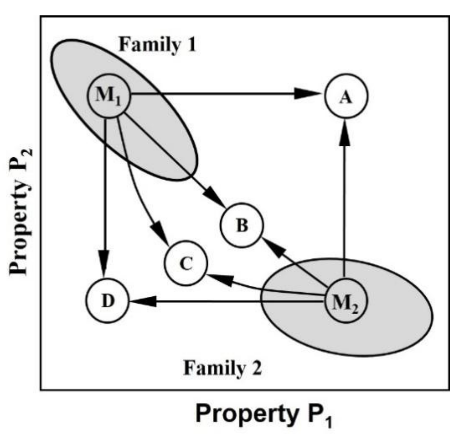
Figure 14 schematically shows the fields occupied by two families of materials, plotted along the axis of properties P1 and P2. Materials M1 and M2 are identified in each field and the properties of the mixture reflect the properties of its constituent materials, which can be combined in several possible ways.
Point A is the ideal situation. It has the best properties of the two families of materials.
Point B satisfies the “rule of mixtures”. The best result of the overall properties that can be obtained in structural composites is often the arithmetic average of the properties of the components, weighted by their volume fractions.
Point C is the “weaker links dominate” rule. The overall property of the mixed materials is lower than that of the rule of mixture, and the arithmetic mean value of the mixed materials is closer to the harmonic value.
Point D is the “worst of both” scenario, which is not desirable.
In this paper, two kinds of wood-based sandwich structures were designed (pyramid and interlocking grid). Through the analysis of their properties, it can be concluded that their properties are between point A and point B; the properties of the pyramid structure and the interlocking grid structure are better than their own constituent material properties.
According to Gibson and Ashby’s research on cellular solids, the design of a structure and the properties of cellular solids depends on the cell structure. Cell structure can be simplified to support rods and nodes, connected by rods in the structure. Different numbers of support rods and nodes will form different forms of cell structures, and the density and mechanical properties of cellular solids will be different. The structure of cellular solids is mainly divided into two structural forms: the structure dominated by bending and the structure dominated by stretching. When the cell structure is a structure dominated by tension and external load is applied, the support rod mainly bears axial load, and the support rod mainly bears tensile force. When the cell structure is a structure dominated by bending and is subjected to compressive load, the support rod of the structure may rotate due to resisting external force, resulting in bending deformation of the whole structure. When the cell structure is subjected to a compressive load, the stretching-dominant structure is more effective than the bending-dominant structure, because at this time, the support rod is in the fully loaded state of stretching or compression. For a 2D cell structure, the classification of cell structures can be expressed by the Maxwell stability number [11]. The Maxwell stability number can be expressed as:
where is the number of supporting rods and is the number of nodes.
When the Maxwell stability number is negative, the structure is dominated by bending, and when it is positive, the structure is dominated by stretching.
In the wood-based pyramid structure, is 4, is 8 and is −11. In the wood-based interlocking grid structure, is 16, is 6 and is 7. Therefore, the wood-based pyramid structure is a structural form dominated by bending, and the wood-based interlocking grid structure is a structural form dominated by stretching. In a bending-dominated structure under the action of a load, the internal rod element of the structure resists the external force with bending deformation, and the rod has the characteristics of large bending stress and deformation. In a stretching-dominated structure under the action of a load, the internal bearing plate of the structure resists the external force with axial deformation, the bending deformation can be ignored, and the deformation of the bearing plate is small. Compression experiments also show that the bearing capacity of wood-based interlocking grid structures is much greater than that of wood-based fund tower structures. Under the same or similar relative density of cell structure, the modulus and initial yield strength of the cell structure dominated by stretching are much larger than those of structures dominated by bending. This makes the cellular solids dominated by stretching more attractive than the cellular solids dominated by bending in application for lightweight structures. In the compression process of a cell structure dominated by bending, although its stiffness and strength are low, its ability to absorb energy is good, and it is an ideal material for buffering and packaging.
4.3.4. Finite Element Analysis
The finite element analysis was based on Auto Inventor to predict the deformation process of wood-based sandwich structure under quasi-static compression. The geometric parameters of the finite element analysis model were the same as those of the experimental specimen.
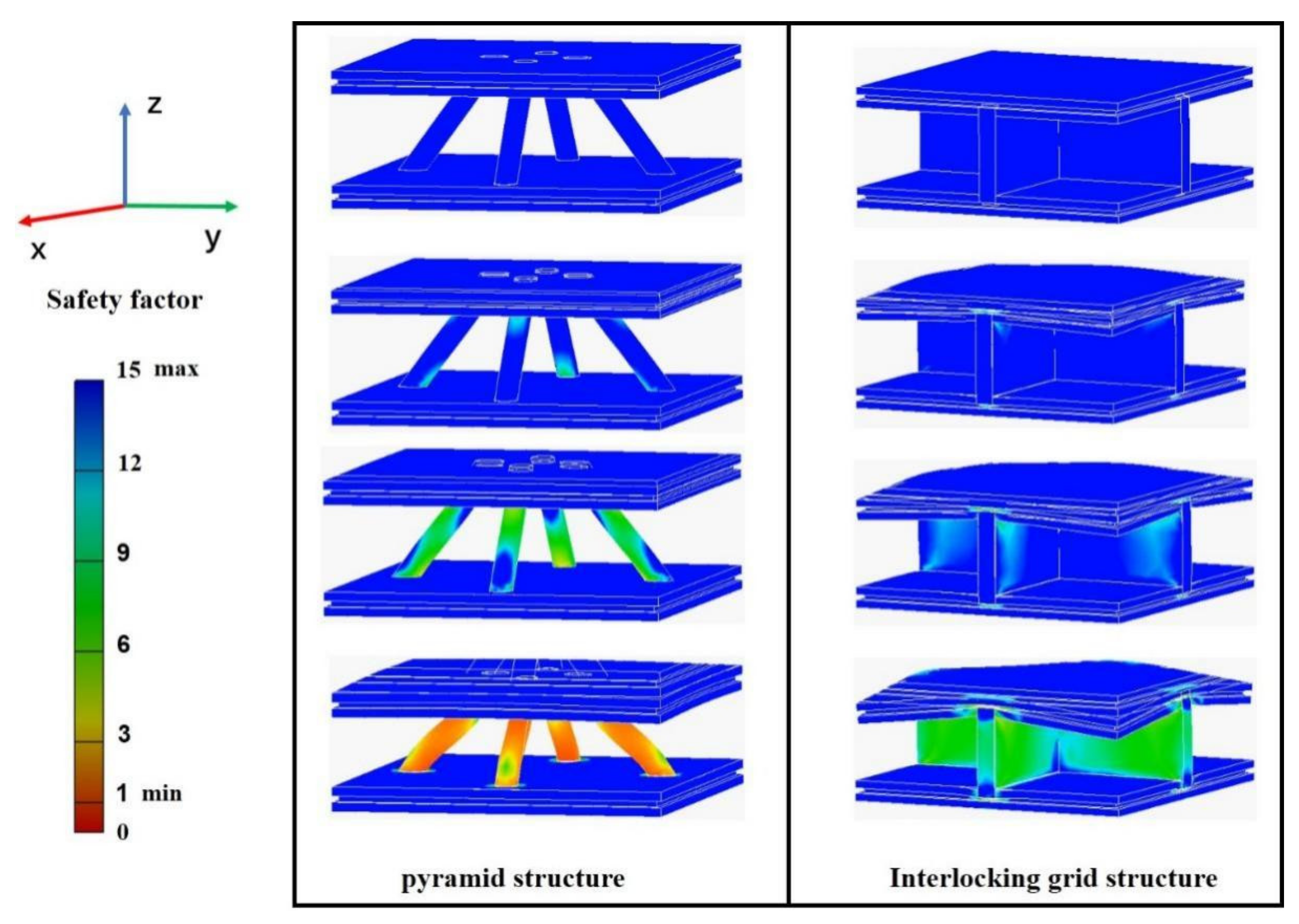
In the simulation process, the fixed plates of the upper and lower panels were made of structural steel; the upper and lower panels of the pyramid structure were fixedly connected with the core by four round rods as the core model; and the upper and lower panels of the interlocking grid structure model were fixedly connected with the bearing plate. The lower panel of the model was fixed horizontally, and the load was applied on the upper panel. It is difficult to quantitatively describe the elastic–plastic changes of wood-based structures by quasi-static compression simulation. Therefore, this paper can only qualitatively analyze the change state of the specimen under flat compression load. The entity unit selected for the model was C3D4. The components in the model were connected by gluing, and the model was connected with the upper and lower fixing plates by separating but without sliding. Based on the ultimate stress (50.28 MPa) of the material in the middle of the model, the bearing capacity of the two structural specimens was analyzed. It was concluded that the bearing capacity of the interlocking grid structure specimen was much greater than that of the pyramid structure specimen. In the structural design of building engineering, the safety factor is usually used to reflect the safety degree of the structure. Therefore, the structural failure state and failure order can be judged from the safety factor. The safety factor distribution of the simulated structure of the two structures is shown in Figure 15. In the simulation results, the failure of the pyramid structure first occurred at the root of the core. With the increase in the load, the core stress increased gradually and was transmitted to the panel in contact with the core. The stress at the panel diffused with the increase in the external load until the panel was destroyed. The failure of the interlocking grid structure first occurred in the contact area between the bearing plate and the upper and lower panels. With the increase in external load, the stress acting on the bearing plate gradually expanded from the upper and the lower areas to the middle area. At the same time, the upper panel began to deform in the contact area, the deformation expanded to the four sides, and the stress of the bearing plate gradually expanded from the edge to the center, covering the whole panel.
The simulation results showed that, when the ultimate stresses of the materials of the middle supports of the two structures are the same, the failure degree of the pyramid structure was greater than that of the interlocking grid structure, which was consistent with the results of the specimen experiment.
4.4. Performance Analysis
Among the pyramid structure specimens, the specimen with WPC as the panel had the largest bearing capacity and the specimen with Larch finger-jointed lumber as the panel had the smallest bearing capacity. The load-bearing capacity of the pyramid structure specimens was directly proportional to the density of the panel materials, and the greater the density of the panel materials, the greater the load-bearing capacity of the specimens. However, the overall performance of the pyramid structure with OSB as the panel was the best.
Among the interlocking grid structure specimens, the specimen with OSB as the panel material had the largest load-bearing capacity. The overall performance of the interlocking grid structure with OSB as the panel was still the best in terms of compression strength, specific strength, and mass–load ratio.
The core material of the pyramid structure specimen was birch, and the bearing plate of the interlocking grid structure specimen was larch finger-joined lumber. According to Table 2, the density value and compressive MOR value of these two materials were approximately equal, but the compressive MOE value of birch material was 1.93 times that of the larch finger-joined lumber. Through the flat compression mechanical property experiment of the two structures, we completed analyses of the bearing capacity, the displacement, and the failure form of the specimens. It can be observed from Figure 9 that the bearing capacity of the interlocking grid structure specimen was 122.97 kN; the bearing capacity of the pyramid structure specimen was 12.96 kN; the bearing capacity of the interlocking grid structure specimen was 9.49 times that of the pyramid structure specimen; and the bearing capacity of the interlocking grid structure specimen was much greater than that of the pyramid structure specimen. The deformation of the interlocking grid structure specimen under the ultimate load was 10.28 mm, and the deformation of the pyramid structure specimen under the ultimate load was 7.33 mm. The deformation resistance of the interlocking grid structure specimen was 28.69% higher than that of the pyramid structure specimen. After comprehensively comparing the bearing capacity, compressive strength, specific strength, and mass–load ratio of the specimens, the performance of the pyramid structure and the interlocking grid structure specimens with OSB as the panel showed the best performance.
The quasi-static compression performance of the specimens was analyzed by finite element methods. Because wood materials are anisotropic materials, the bearing capacity of the specimens could be simulated, but the elastoplasticity of wood materials cannot be accurately described. The simulation analysis showed that the bearing capacity, structural safety factor, and failure mode of the six types of specimens were consistent with those in the experimental test.
Wood-based materials are materials with low density and high strength. The apparent density of the six specimens prepared in the test was lower than that of the constituent materials. A material density–strength diagram is shown in Figure 16. The apparent densities of the six specimens were all in the low-density area, but the overall flat compressive strength of the structure was high. According to Figure 10, the strength values of the six specimens were between 103.86 MPa and 511.63 MPa, categorizing them as high-strength materials in the natural material area. The strength of the three interlocking grid structure specimens was higher than that of the composite lattice structure.
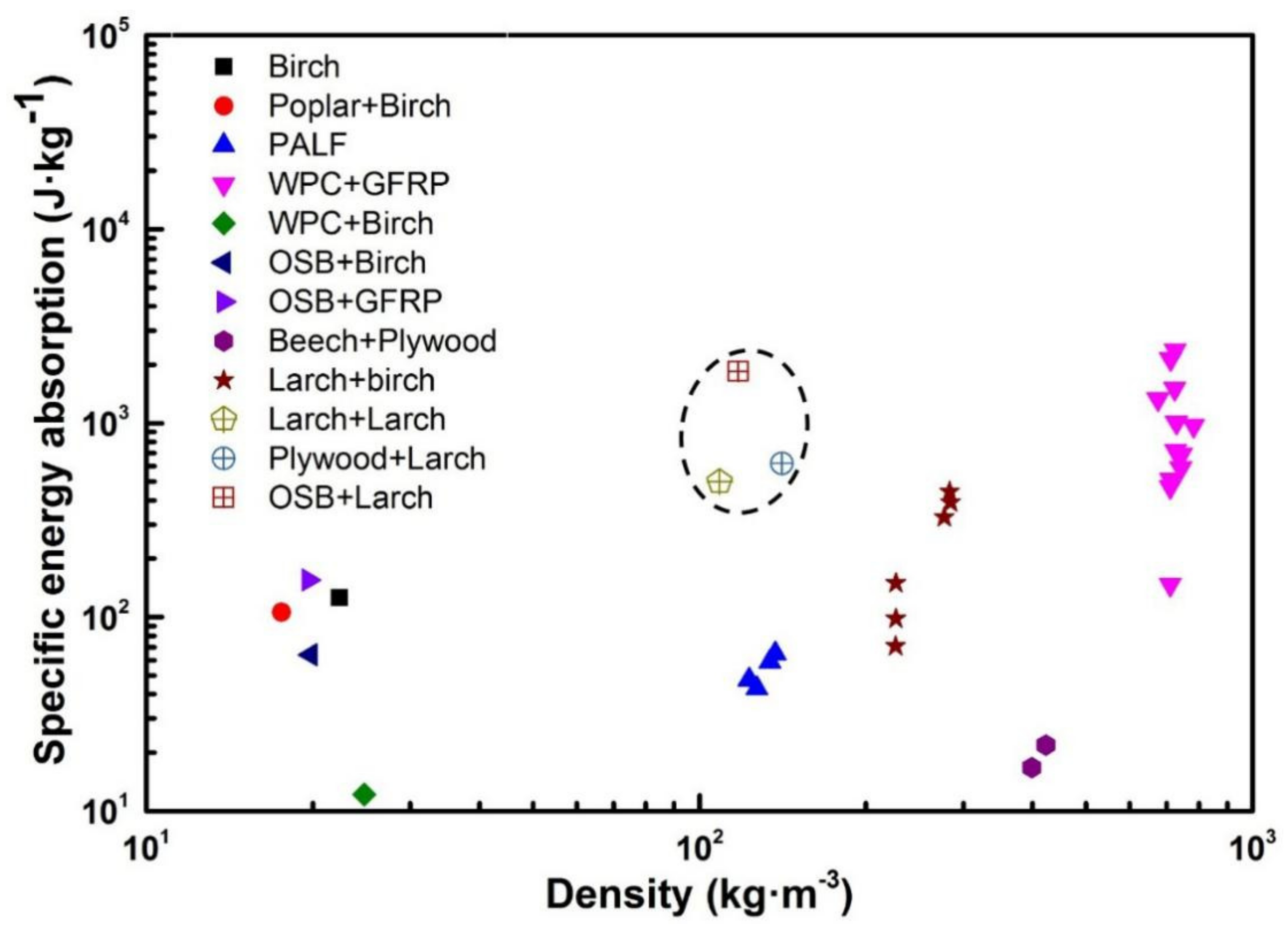
Specific energy absorption (SEA), namely the energy absorbed by structural materials per unit mass, is a measure of material utilization efficiency in the energy absorption process: the higher the value, the better.
The specific energy absorption of wood-based sandwich structures is shown in Figure 17. In Figure 17, the dotted line part is the wood-based interlocking grid structure specimens studied in this paper, and the rest is the wood-based lattice sandwich structure specimens.
The combined materials of the specimens are birch sawn timber, PALF [16], WPC, GFRP, OSB, birch [19,20], poplar LVL panels [32], beech, plywood, and larch. The wood-based sandwich structures were composed of one or two of the above materials. The specific energy absorption values of the interlocking grid structure specimens were 498.16 J/kg, 618.28 J/kg, and 1841.22 J/kg. The specific energy absorption values of the specimens were close to the maximum values of the WPC + GFRP sandwich structure, but the structural density was much lower.
According to the above analysis, the interlocking grid structure specimens had high bearing capacity, so the performances of the interlocking grid structure specimens were also better than those of the pyramid structure specimens in three aspects: compressive strength, specific strength, and mass–load ratio. The interlocking grid structure specimen also had high energy absorption capacity. The interlocking grid structure specimens were also more convenient in preparation, installation, and assembly than the pyramid structures.
The specimens in this study had large sizes, and could be used conveniently as components of a built structure. At the same time, the structural size of the specimens could be adjusted according to the application of a given building’s structure. If the digital wood-processing technology were used to process the wood-based sandwich structure, it could minimize the error of the wood-based sandwich structure in the processing stage, as well as carry out customized processing to form a light wood structure building with a combination of digital innovation and artistic design. The topology of sandwich-structured core layers and the reinforcement of panel materials are future directions for research work.
4.5. Discussion
From Figure 9 and Figure 10, the difference in the mechanical properties of the two wood-based sandwich structures can be observed. Based on the results of previous researchers, in order to improve the mechanical properties of wood-based sandwich structures, the design structure can be improved through three factors. First, the material and configuration of the core layer. At present, the configuration of the wood-based core layer mainly includes hexagonal honeycomb [9], triangle [33], quadrangle [33], pyramid [16,17,22,23], straight column [18], and X type [19,20,21]. The core layer is the main body bearing the external load. With different materials and configurations of the core layer, the ability to bear the load is different. Future research can explore core density gradient design and core structure variable section design. Secondly, one can increase the effective contact area between the core and the panel. Under the action of the external load, the area where the core layer is in contact with the panel is the area of concentrated stress, which is the area where the structural materials are most likely to be damaged. The increase in the effective contact area between the core layer and the panel can disperse the stress and effectively improve the bearing capacity of structural materials. Finally, the panel can be enhanced. The strengthening of panel materials and structures can effectively improve the bearing capacity of wood-based sandwich structures.
The wood-based sandwich structure studied by Wang et al. [34] can effectively improve the compressive strength and elastic modulus of wood-based sandwich structures. A method of increasing the effective contact area between the core layer, the panel, and panel reinforcement was adopted. The wood-based sandwich structure studied by Zheng et al. [35] and Jerzy et al. [36] can effectively improve the mechanical properties of the sandwich structure. The method they used involved changing the core material and the configuration, increasing the effective contact area between the core and the panel.
Additionally, the research shows that various factors, such as processing, manufacturing, installation, size, height, density, and direction of the core layer, as well as the surface stiffness along the long axis of the sandwich plate, need to be considered when manufacturing wood-based sandwich structures.
5. Conclusions
Through the static flat test of two structural types (pyramid structure and interlocking grid structure) of wood-based sandwich structures, the following conclusions were reached:
- (1)
- The apparent density of wooden pyramid sandwich structures and interlocking sandwich structures was lower than that of their respective constituent materials. However, the overall flat compressive strength of the two structures was higher than that of their own constituent materials, which were high-strength natural materials. The mechanical properties of the two structures were better than their constituent materials. Finite element analysis clearly showed the changes in the two structures with force and time. The failure modes of the two structures analyzed by finite element method were in agreement with the experimental results.
- (2)
- The failure modes of the wood-based sandwich structures were similar: the cores were broken and the panels were cracked. The failure position mainly started from the intersection between the core structure and the panel. With the increase in load, the crack continued to expand until the specimen failed. This was because the intersection of the core layer and the panel contact was the weakest place of structural strength. When subjected to external load, the stress was mainly concentrated at the intersection of the core layer and the panel contact. The stress at the intersection was much larger than the allowable stress range for core and panel materials, and was the main mode of structural failure. This was consistent with the location of failure determined by finite element method.
- (3)
- The mechanical properties of wood-based sandwich structures mainly depend on the type of structure, and the constituent materials of the structure occupy a secondary position. The mechanical properties of the interlocking grid structure specimens were clearly better than those of the pyramid structure specimens.
- (4)
- The theoretical analysis showed that the wood-based interlocking grid structure had a tensile-dominant structure, and the wood-based pyramid structure has a bending-dominant structure. The mechanical properties of the two structures were consistent with the experimental results.
Author Contributions
Conceptualization, D.Y. and C.F.; methodology, D.Y. and C.F.; software, D.Y. and C.F.; validation, D.Y. and C.F.; formal analysis, D.Y.; investigation, D.Y.; resources, D.Y.; data curation, D.Y.; writing—original draft preparation, D.Y. and C.F.; writing—review and editing, C.F.; supervision, C.F.; project administration, D.Y.; funding acquisition, D.Y. All authors have read and agreed to the published version of the manuscript.
Funding
This research was funded by the Heilongjiang Province postdoctoral research startup Fund (Year 2021), and the Natural Science Foundation of Heilongjiang Province, grant number LH2020F010.
Institutional Review Board Statement
Not applicable.
Informed Consent Statement
Not applicable.
Data Availability Statement
The study did not report any data, available upon reasonable request.
Conflicts of Interest
No conflict of interest exists in the submission of this manuscript, and the manuscript was approved by all authors for publication. I would like to declare on behalf of my co-authors that the work described was original research that has not been published previously, and not under consideration for publication elsewhere, in whole or in part. All the authors listed have approved the manuscript that is enclosed.
References
- Jian, X.; Du, Y.; Yang, W.; Wu, Q.; Xu, X.; Yao, D.; Wei, X.; Chen, Z. Research Progress on Design and Mechanical Properties of Lightweight Composite Sandwich Structures. J. Astronaut. 2020, 41, 749–760. [Google Scholar] [CrossRef]
- Ye, G.; Bi, H.; Hu, Y. Compression behaviors of 3D printed pyramidal lattice truss composite structures. Compos. Struct. 2020, 233, 111706. [Google Scholar] [CrossRef]
- Imani, M.; Donn, M.; Balador, Z. Bio-inspired Materials: Contribution of Biology to Energy Efficiency of Buildings. In Handbook of Ecomaterials; Martínez, L.M.T., Kharissova, O.V., Kharisov, B.I., Eds.; Springer International Publishing: Cham, Switzerland, 2019; pp. 2213–2236. [Google Scholar]
- Pacheco-Torgal, F.; Labrincha, J.A. Biotechnologies and bioinspired materials for the construction industry: An overview. Int. J. Sustain. Eng. 2014, 7, 235–244. [Google Scholar] [CrossRef] [Green Version]
- Al-Obaidi, K.M.; Ismail, M.A.; Hussein, H.; Rahman, A.M.A. Biomimetic building skins: An adaptive approach. Renew. Sustain. Energy Rev. 2017, 79, 1472–1491. [Google Scholar] [CrossRef]
- Krausmann, F.; Gingrich, S.; Eisenmenger, N.; Erb, K.H.; Haberl, H.; Fischer-Kowalski, M. Growth in global materials use, GDP and population during the 20th century. Ecol. Econ. 2009, 68, 2696–2705. [Google Scholar] [CrossRef]
- Ahamed, M.K.; Wang, H.; Hazell, P.J. From biology to biomimicry: Using nature to build better structures A review. Constr. Build. Mater. 2022, 320, 126195. [Google Scholar] [CrossRef]
- Mustapha, K.B. Manufacturing, Applications and Mechanical Properties of Lightweight Wood Based Sandwich Panels. Encycl. Renew. Sustain. Mater. 2020, 1, 411–416. [Google Scholar] [CrossRef]
- Ashby, M.F.; Brechet, Y.J.M. Designing hybrid materials. Acta Mater. 2003, 51, 5801–5821. [Google Scholar] [CrossRef]
- Gibson, L.J.; Ashby, M.F. Cellular Solids-Structure and Properties; Cambridge University Press: Cambridge, UK, 1999. [Google Scholar]
- Schaedler, T.A.; Carter, W.B. Architected Cellular Materials. Annu. Rev. Mater. Res. 2016, 46, 187–210. [Google Scholar] [CrossRef]
- Wu, L.; Pan, S. Survey of Design and Manufacturing of Sandwich Structures. Mech. China 2009, 28, 40–45. [Google Scholar]
- Wu, L.; Xiong, J.; Ma, L.; Wang, B.; Pan, S.; Liu, H. Integrated design of lightweight multifunctional Sandwich structures. Mech. Eng. 2012, 34, 8–18. [Google Scholar] [CrossRef]
- Birman, V.; Kardomateas, G.A. Review of current trends in research and applications of sandwich structures. Compos. Part B Eng. 2018, 142, 221–240. [Google Scholar] [CrossRef]
- Jin, M.; Hu, Y.; Wang, B. Compressive and bending behaviors of wood based two dimensional lattice truss core sandwich structures. Compos. Struct. 2015, 124, 337–344. [Google Scholar] [CrossRef]
- Li, S.; Qin, J.; Li, C.; Feng, Y.; Zhao, X.; Hu, Y. Optimization and compressive behavior of composite 2-D lattice structure. Mech. Adv. Mater. Struct. 2018, 27, 1213–1222. [Google Scholar] [CrossRef]
- Li, S.; Qin, J.; Wang, B.; Zheng, T.; Hu, Y. Design and compressive behavior of a photosensitive resin-based 2-D lattice structure with variable cross-section core. Polymers 2019, 11, 186. [Google Scholar] [CrossRef] [Green Version]
- Qin, J.; Zheng, T.; Li, S.; Cheng, Y.; Xu, Q.; Ye, G.; Hu, Y. Core configuration and panel reinforcement affect compression properties of wood- based 2-D straight column lattice truss sandwich structure. Eur. J. Wood Wood Prod. 2019, 77, 539–546. [Google Scholar] [CrossRef]
- Zheng, T.; Yan, H.; Li, S.; Cheng, Y.; Zou, L.; Hu, Y. Compressive behavior and failure modes of the wood based double X type lattice sandwich structure. J. Build. Eng. 2020, 30, 101176. [Google Scholar] [CrossRef]
- Zheng, T.; Li, S.; Xu, Q.; Hu, Y. Core and panel types affect the mechanical properties and failure modes of the wood based XX type lattice sandwich structure. Eur. J. Wood Wood Prod. 2021, 1, 1253–1268. [Google Scholar] [CrossRef]
- Zou, L.; Zheng, T.; Li, S.; Zhao, X.; Wang, L.; Hu, Y. Compression behaviour of the wood-based X-type lattice sandwich structure. Eur. Wood Wood Prod. 2021, 79, 139–150. [Google Scholar] [CrossRef]
- Yang, D.; Fan, C.; Hu, Y. Optimization and Mechanical Properties of Fabricated 2D Wood Pyramid Lattice Sandwich Structure. Forests 2021, 12, 607. [Google Scholar] [CrossRef]
- Yang, D.; Hu, Y.; Fan, C. Compression Behaviors of Wood-based Lattice Sandwich Structure. Bioresources 2018, 13, 6577–6590. [Google Scholar] [CrossRef]
- Cheng, X.; Zhang, X.; Zhang, Q.; Hu, Q.; Yue, K. Research on bending properties of Birch Plywood Treated by Liquefied Nitrogen. J. For. Eng. 2009, 23, 52–55. [Google Scholar]
- Hao, M.; Hu, Y.; Wang, B.; Liu, S. Mechanical behavior of natural fiber-based isogrid lattice cylinder. Compos. Struct. 2017, 176, 117–123. [Google Scholar] [CrossRef]
- Smardzewski, J.; Maslej, M.; Wojciechowski, K.W. Compression and low velocity impact response of wood based sandwich panels with auxetic lattice core. Eur. J. Wood Wood Prod. 2021, 79, 797–810. [Google Scholar] [CrossRef]
- Hao, J.; Wu, X.; Oporto-Velasquez, G.; Wang, J.; Dahle, G. Compression Properties and Prediction of Wood Based Sandwich Panels with a Nove Taiji Honeycomb Core. Forests 2020, 11, 886. [Google Scholar] [CrossRef]
- Krzysztof, P.; Jerzy, S. Bending Behavior of Lightweight Wood-Based Sandwich Beams with Auxetic Cellular Core. Polymer 2020, 12, 1723. [Google Scholar] [CrossRef]
- Jia, W. The application of “32mm system”. Furniture 1992, 65, 22–24. [Google Scholar] [CrossRef]
- Hu, M.; Liu, C.; Li, W. Mechanical Behavior of OSB under Different Loading Speeds in the Three Point Bending Method. Packag. Eng. 2019, 40, 90–95. [Google Scholar] [CrossRef]
- Wu, L.; Xiong, J.; Ma, L.; Wang, B.; Zhang, G.; Yang, J. Processes in the study on novel composite sandwich panels with lattice truss cores. Adv. Mech. 2012, 42, 41–67. [Google Scholar]
- Klímek, P.; Wimmer, R.; Brabec, M.; Sebera, V. Novel Sandwich Panel with Interlocking Plywood Kagome Lattice Core and Grooved Particleboard Facings. BioResources 2016, 11, 195–208. [Google Scholar] [CrossRef] [Green Version]
- Zuhri, M.Y.M.; Guan, Z.W.; Cantwell, W.J. The mechanical properties of natural fibre based honeycomb core materials. Compos. Part B 2014, 58, 1–9. [Google Scholar] [CrossRef]
- Wang, L.; Hu, Y.; Zhang, X.; Li, S.; Li, S.; Zhang, H. Design and compressive behavior of a wood based pyramidal lattice core sandwich structure. Eur. J. Wood Wood Prod. 2020, 78, 123–134. [Google Scholar] [CrossRef]
- Chen, Z.; Yan, N.; Brew, S.S.; Smith, G.; Deng, J. Investigation of mechanical properties of sandwich panels made of paper honeycomb core and wood composite skins by experimental testing and finite element modelling methods. Eur. J. Wood Wood Prod. 2013, 5, 311–319. [Google Scholar] [CrossRef]
- Smardzewski, J. Experimental and numerical analysis of wooden sandwich panels with an auxetic core and oval cells. Mater. Des. 2019, 183, 108159. [Google Scholar] [CrossRef]
Figure 1.
Diagram of wood-based pyramid sandwich structure. (a) Axonometric drawing; (b) section view.
Figure 1.
Diagram of wood-based pyramid sandwich structure. (a) Axonometric drawing; (b) section view.

Figure 2.
Fabrication of pyramid sandwich structure.

Figure 3.
Fabrication of pyramid sandwich structure. (a) WPC + Birch; (b) OSB + Birch; (c) Larch + Birch.
Figure 3.
Fabrication of pyramid sandwich structure. (a) WPC + Birch; (b) OSB + Birch; (c) Larch + Birch.

Figure 4.
Failure modes of wood-based pyramid structure specimens. (a) WPC + Birch; (b) OSB + Birch; (c) Larch + Birch.
Figure 4.
Failure modes of wood-based pyramid structure specimens. (a) WPC + Birch; (b) OSB + Birch; (c) Larch + Birch.

Figure 5.
Diagram of interlocking grid structure. (a) Axonometric drawing; (b) section view.

Figure 6.
Fabrication of interlocking grid structure.

Figure 7.
Specimens of interlocking grid structure. (a) Larch + Larch; (b) Plywood + Larch; (c) OSB + Larch.
Figure 7.
Specimens of interlocking grid structure. (a) Larch + Larch; (b) Plywood + Larch; (c) OSB + Larch.

Figure 8.
Failure mode of interlocking grid structure specimens. (a) Larch + Larch; (b) Plywood + Larch; (c) OSB + Larch.
Figure 8.
Failure mode of interlocking grid structure specimens. (a) Larch + Larch; (b) Plywood + Larch; (c) OSB + Larch.

Figure 9.
Load–displacement curves of wood-based pyramid sandwich structure and wood-based interlocking grid structure. (a) Larch + Birch; (b) WPC + Birch; (c) OSB + Birch; (d) Larch + Larch; (e) Plywood + Larch; (f) OSB + Larch.
Figure 9.
Load–displacement curves of wood-based pyramid sandwich structure and wood-based interlocking grid structure. (a) Larch + Birch; (b) WPC + Birch; (c) OSB + Birch; (d) Larch + Larch; (e) Plywood + Larch; (f) OSB + Larch.

Figure 10.
Performance comparison of wood-based pyramid structure and wood-based interlocking grid structure. (a) Bearing capacity; (b) compressive strength; (c) specific strength; (d) mass–load ratio.
Figure 10.
Performance comparison of wood-based pyramid structure and wood-based interlocking grid structure. (a) Bearing capacity; (b) compressive strength; (c) specific strength; (d) mass–load ratio.

Figure 11.
Force analysis of a single core.

Figure 12.
Force analysis of supporting plate of interlocking grid structure. (a) Force diagram; (b) force deformation diagram; (c) force decomposition diagram.
Figure 12.
Force analysis of supporting plate of interlocking grid structure. (a) Force diagram; (b) force deformation diagram; (c) force decomposition diagram.

Figure 13.
Stress analysis of the interlocking grid structure panel. (a) Stress and deformation diagram of pane; (b) stress decomposition diagram of pane.
Figure 13.
Stress analysis of the interlocking grid structure panel. (a) Stress and deformation diagram of pane; (b) stress decomposition diagram of pane.

Figure 14.
Possibilities of mixing [9].
Figure 14.
Possibilities of mixing [9].

Figure 15.
Safety factor distribution of the simulation structure.

Figure 16.
Relationship between compressive strength and density of wood-based sandwich structure [31].
Figure 16.
Relationship between compressive strength and density of wood-based sandwich structure [31].

Figure 17.
Specific energy absorption of wood-based sandwich structure.


Table 1.
The structural parameters of the specimen.
| Type | a | b | c | d | tf | t | l | φ |
|---|---|---|---|---|---|---|---|---|
| Pyramid | 190 | 3 | 3 | 12 | 12 | 46 | 60 | 52° |
Table 2.
Mechanical properties of raw materials.
| Material | Shaving Direction | ρ (g/cm3) | MOE (GPa) Compressive | MOR (MPa) Compressive |
|---|---|---|---|---|
| OSB [20] | Major axis | 0.61 | 3.52 | 22.37 |
| Minor axis | 3.05 | 20.23 | ||
| Birch Plywood [23] | Transverse | 0.82 | 5.23 | 58 |
| Longitudinal | 9.42 | 74 | ||
| WPC [16] | — | 1.16 | 1.14 | 37.03 |
| Larch finger-jointed lumber | Longitudinal | 0.51 | 26.68 | 50.30 |
| Birch [15] | Longitudinal | 0.58 | 51.47 | 50.28 |
Table 3.
Parameters of interlocked grid structure specimens.
| Group | Type | Materials | a | b | tf | c | t | h |
|---|---|---|---|---|---|---|---|---|
| 1 | Interlocking grid | OSB + Larch | 190 | 3 | 12 | 3 | 46 | 62 |
| 2 | Larch + Larch | 190 | 3 | 12 | 3 | 46 | 62 | |
| 3 | Plywood + Larch | 190 | 3 | 12 | 3 | 46 | 62 |
Publisher’s Note: MDPI stays neutral with regard to jurisdictional claims in published maps and institutional affiliations. |
© 2022 by the authors. Licensee MDPI, Basel, Switzerland. This article is an open access article distributed under the terms and conditions of the Creative Commons Attribution (CC BY) license (https://creativecommons.org/licenses/by/4.0/).
Share and Cite
MDPI and ACS Style
Yang, D.; Fan, C. The Mechanical Properties of Wood-Based Grid Sandwich Structures. Forests 2022, 13, 877. https://doi.org/10.3390/f13060877
AMA Style
Yang D, Fan C. The Mechanical Properties of Wood-Based Grid Sandwich Structures. Forests. 2022; 13(6):877. https://doi.org/10.3390/f13060877
Chicago/Turabian StyleYang, Dongxia, and Changsheng Fan. 2022. "The Mechanical Properties of Wood-Based Grid Sandwich Structures" Forests 13, no. 6: 877. https://doi.org/10.3390/f13060877
Note that from the first issue of 2016, this journal uses article numbers instead of page numbers. See further details here.