Article

Bending Stiffness of Hybrid Wood-Metal Composite Beams: An Experimentally Validated Numerical Model

1
Department of Wood Science and Technology, Biotechnical Faculty, University of Ljubljana, Jamnikarjeva 101, 1000 Ljubljana, Slovenia
2
M Sora d.d., Trg Svobode 2, 4226 Žiri, Slovenia
*
Author to whom correspondence should be addressed.
Forests 2021, 12(7), 918; https://doi.org/10.3390/f12070918
Submission received: 10 June 2021 / Revised: 11 July 2021 / Accepted: 12 July 2021 / Published: 14 July 2021

Abstract

:
This paper presents an experimentally validated model for the computational analysis of metal-reinforced wooden composites. The model can be used in both research and in industry to effectively estimate how much a certain composite design improves the bending stiffness and strength of a hybrid metal-reinforced wooden component. A model based on computer simulations allows the prediction and analysis of the mechanical behaviour of a hybrid composite material consisting of several interconnected components made of different base materials. The model for different boundary conditions and parameters provides the correct data on stiffness, especially bending, and the associated maximum displacements. It allows for a variation of the mechanical and geometrical properties, and makes it possible to observe the initiation of irreversible change in the window-frame member. The model enables parametrical simulations to find the optimum layout of reinforcements in the window-frame member, as well as to make estimations of the maximum performance of certain designs.

1. Introduction

After decades of neglect, wood has been gaining popularity because of its aesthetic value, wide range of properties, and renewability. As a construction material, wood offers good weight-specific stiffness and strength while simultaneously providing excellent insulation. In contrast to building materials such as metals, concretes, and plastics, wood also has a positive environmental impact by reducing CO2 emissions. As environmental regulations and life-cycle assessments (LCAs) become increasingly important, wood is expected to be more heavily relied on in the future [1,2].
The use of wood covers many mechanical applications, ranging from Formula 1 racing cars to homes. However, on its own, wood lacks stiffness and strength compared to other materials (for example, fibre-reinforced polymers (FRPs) and metals). Therefore, new technologies are being introduced to enhance wood based on hybrid composite designs [3,4,5,6,7]. Modern beams can thus be strengthened in the production phase [8], or old wooden beams can be repaired and retrofitted by adding FRP laminates [9,10,11,12,13,14,15,16,17] and honeycomb sandwich panels [18]. This strengthening can even be made reversible [19] or, in certain cases, adaptive [20]. While the use of FRPs is very common [6,7,21,22,23,24,25], the potential for reinforcement with metals remains under-addressed and under-investigated, despite their comparatively higher stiffness and strength. Moreover, equal strengths in the tensile and compressive directions make metals [26,27] very appropriate for reinforcement beams that are subjected to alternating loads [28]. There are not many attempts to use aluminium as a reinforcing material. Steel is much more commonly used due to higher elastic moduli and better thermal properties. There are not many attempts to use aluminium as a reinforcing material. Steel is much more commonly used due to its higher elastic moduli and better thermal properties [26,29] Jasieńko [27] studied the interaction of a glued-in steel bar over the cross section of a reinforced wood element. The experimental results showed an irregular distribution along the bonding joint of normal and shear stresses. Some researchers [23] compared experiments on glulam beams reinforced by plates. Their results confirmed the importance of the reinforcements in enhancing the overall mechanical behaviour of wooden beams. Kim and Harries [23] showed that there is a limit to the reinforcement-to-wood ratio beyond which the ultimate load cannot increase.
Composite wooden beams are currently expanding to the window-frame industry (Figure 1), as the contemporary design of windows with very large dimensions has exceeded the limits of wood’s load-bearing capacity [30,31,32]. Thin window frames with a size of 5 m are currently manufactured solely with aluminium frames, while wood, the oldest window-frame material with excellent thermal insulation properties, has not yet been able to penetrate this segment due to its stiffness is inferior to that of aluminium. New solutions are therefore being sought, and introducing reinforcements into wooden window frames appears to be the next rational step.
The motivation for this study comes from the fact that a composite structure allows for a case-specific customisation, and that this process can be greatly improved with computational prototyping [33,34,35,36]. The goal of this study is therefore to present a validated model for the computational analysis of metal-reinforced wooden composites, which can be used in research and industry to effectively estimate how much a certain composite design improves the bending stiffness and strength of a hybrid, metal-reinforced wooden component.

2. Materials and Methods

2.1. Computer Modelling

The three-dimensional numerical model is based on the finite-element method (FEM) for use in Simulia Abaqus [37], where the following material and contact models are implemented to simulate the general case of a hybrid, reinforced, wooden composite: (i) an isotropic elastic–plastic model for reinforcements; (ii) an anisotropic elastic–plastic model for wood; and (iii) a traction–separation model for adhesives.
The model is intended to allow for simulations of the elastic behaviour of hybrid wood–metal composites, while also enabling the prediction and observation of plastification onset and damage initiation. Plastic deformation and damage progression are not covered in this model, since the model is intended to evaluate the mechanical performance in operating regimes until the onset of failure. However, the model can be extended to cover failure regimes in the future. In addition, the model is currently limited to metal reinforcements for two reasons: (i) FRP reinforcements in hybrid wood composites have already been numerically addressed to some extent [17,19,23,34,35,36] and (ii) the industrial requirements call for metal (especially aluminium) reinforcements in the case of large window frames. Window-frame manufacturers rely on aluminium for its price, extrusion simplicity, and their experience of combining it with wood, although until now only in the form of protective covers for the wooden frames of smaller windows. However, the presented model can also be extended in the future by including other reinforcement materials, for example, anisotropic glass FRP or carbon FRP.

2.1.1. Material Behaviour

The presented computer model is based on the finite-element method (FEM) and implemented in Abaqus software [37]. The model encompasses constitutive material models with recommended values of the material properties, geometrical representation, and interaction inclusion. The model allows for a variation of the material, geometrical, interaction, and boundary-condition parameters. The material’s behaviour is limited to the elasticity with an irreversible deformation limit. In the scope of the FEM, the material behaviour of continuous domains was modelled with constitutive equations of the type σ = D 1 ϵ , which relate the infinitesimal (logarithmic) deformation tensor ϵ T = [ ϵ 11 ϵ 22 ϵ 33 γ 12 γ 13 γ 23 ] to the true (Cauchy) stress tensor σ T = [ σ 11 σ 22 σ 33 σ 12 σ 13 σ 23 ] through the elasticity tensor D , whose inverse
D 1 = [ 1 / E 1 ν 21 / E 2 ν 31 / E 3 0 0 0 ν 12 / E 1 1 / E 2 ν 32 / E 3 0 0 0 ν 13 / E 1 ν 23 / E 2 1 / E 3 0 0 0 0 0 0 1 / G 12 0 0 0 0 0 0 1 / G 13 0 0 0 0 0 0 1 / G 23 ]
is expressed in terms of engineering constants. For a more compact description, the integer indexes i ,   j ,   k     { 1 ,   2 ,   3 } ;   i j ,   i k ,   j k in this work indicate the associated spatial directions of the material domain.

2.1.2. Modelling of the Wooden Material

Orthotropic Elasticity

In the elasticity tensor from Equation (1), the orthotropic elastic behaviour of the wood is defined with the following engineering constants: (i) Young’s moduli E i , (ii) shear moduli G i j , and (iii) Poisson’s ratios ν i j
ν i j ν j i = E i E j .

Orthotropic Irreversibility Surface

However, stiffness is not the only criterion for evaluating the design of the composite product. It is also necessary for engineers to be able to estimate the onset of irreversible deformation in the product during the design process. With the exception of a few applications where the structural role of the composite component is failure-related, the composite structure’s static, dynamic, or creep-related loading limits must be known so as to limit the product’s operation to a reversible regime only. These limits can be numerically estimated based on the known limits for the wooden domain. Although irreversible change can come in the form of plastic yield, damage, or creep, an irreversibility surface [38] can be used to model the onset of the irreversibility.
The irreversibility surfaces of wood are complex, as they depend on the wood type, wood quality, and the environmental exposure during its growth and preparation. The correct description of the irreversibility surface therefore demands extensive experimental testing, which is normally not justified or beyond the resources available for predictive modelling in regular product development. In this study, a more practical and straightforward approach to the definition of irreversibility surfaces, based on Hill’s surfaces [39,40,41,42], is presented. It relies on the inevitable necessity to perform validation experiments. Here, all the irreversible transformations of the material are modelled based on the quadratic Hill criterion f ( σ ) > 1 . The Hill’s surfaces used [43] assume that the wood is hydrostatically incompressible, and a simplified analytical equation can be used,
f ( σ ) = s 1 ( σ 22 σ 33 ) 2 + s 2 ( σ 33 σ 11 ) 2 + s 3 ( σ 11 σ 22 ) 2 + 2 ( t 1 σ 23 2 + t 2 σ 13 2 + t 3 σ 12 2 )
It is an extension of the Huber–Mises–Hencky criterion, where s i and t i are constants, defined as
s i = 1 2 ( 1 R j j 2 + 1 R k k 2 1 R i i 2 ) ,
t i = 1 2 R j k 2
and R i j = σ ¯ i j / σ 0 are the irreversibility stress ratios, defined with the irreversibility-onset stress σ ¯ i j in relation to some reference stress σ 0 , when the stress σ i j is the only stress the material is subjected to. In the case of an irreversible transformation, the associated flow rule of the small deformation theory defines the plastic strain rate’s direction as normal to the irreversibility surface.

2.1.3. Modelling of the Metal Material

Isotropic Elasticity

In the elasticity tensor from Equation (1), the isotropic elasticity is defined with the isotropic (i) Young’s modulus E = E i , (ii) shear modulus G = G i j , and (iii) Poisson’s ratio ν = ν i j , which are related through
G = E 2 ( 1 + ν )    

Isotropic Irreversibility Surface

The Huber–Mises–Hencky irreversibility criterion f ( σ ) > 1 is used to model the onset of irreversible changes in the metal domain, which evaluates the effective true stresses σ i j based on the hydrostatic-stress-independent irreversibility surface
f ( σ ) = 1 2 ( ( σ 22 σ 33 ) 2 + ( σ 33 σ 11 ) 2 + ( σ 11 σ 22 ) 2 ) + 3 ( σ 23 2 + σ 31 2 + σ 12 2 ) .
Here, σ ¯ represents the stress limit for the onset of the irreversible transformation of the material. The elastic parameters E and ν as well as the irreversible limit parameter σ ¯ are therefore needed for a description of an isotropic material with this model. In the case of an irreversible transformation, the associated flow rule of the small deformation theory again defines the plastic strain rate’s direction as being normal to the irreversibility surface.

2.1.4. Modelling of the Adhesive Joints

A cohesive model relates the traction vector t T = [ t n t s t t ] between two joined surfaces of a cohesive domain with their relative position. The index n here indicates the normal direction to the surface, while s and t indicate the first and second directions in the local tangential-to-contact plane, respectively. The relative position of the two planes is described differently for thin and thick joints. The Abaqus program makes it possible to define constitutive models for cohesive behaviour based on the engineering constants in the stiffness tensor for thin joints, and in the elasticity tensor for thick joints. The uncoupled model, which does not constitute the relations between the n, s, and t directions, was used.
Depending on the thickness of the adhesive layer, the adhesive between the solid domains is modelled based on two different approaches. In the case of the thicker adhesive layers, the adhesive is modelled as an independent material domain, whereas in the case of the very thin adhesive layers it is modelled as a contact interaction. In both cases, the adhesion model is based on the following traction–separation laws.

Modelling of the Thin Adhesive Joints

The thin joints do not exhibit significant geometrical thickness ( T j o i n t 0 ), and are modelled as contacts with the constitutive traction-separation model t = K δ , where δ T = [ δ n δ s δ t ]   is the vector of separation between the joined surfaces. In the stiffness tensor
K = [ K n n 0 0 0 K s s 0 0 0 K t t ]
K n n , K s s and K t t are the stiffness constants in the directions n , s and t , respectively.

Modelling of the Thick Adhesive Joints

The adhesive layers of the thick joints are modelled as geometrically discretised domains. The constitutive model of elastic traction-separation behaviour is defined as t = E ϵ , where ϵ T = [ ϵ n ϵ s ϵ t ] is the separation strain vector of the two surfaces, with the components ϵ x = δ x / T 0 , x     { n ,   s ,   t } . The initial layer thickness T 0 is automatically acquired in Abaqus from the element thickness in the spatially discretised adhesive domain. The elasticity tensor
E = [ E n n 0 0 0 E s s 0 0 0 E t t ] ,
is composed of the elasticity constants E n n , E s s , E t t that are associated with the directions n , s and t in the joint.

Irreversibility Surface

The onset of the irreversible transformation in the adhesive joint is modelled based on the quadratic nominal-stress-based initiation criterion f ( t ) > 1 , where the surface
f ( t ) = ( t n t ¯ n ) 2 + ( t s t ¯ s ) 2 + ( t t t ¯ t ) 2 ,
is defined with the traction limits t ¯ n , t ¯ s and t ¯ t , which are representative when the joint is subjected to unidirectional traction in the n , s or t direction, respectively. Therefore, for a complete model description, the parameters K n n , K s s , K t t , t ¯ n , t ¯ s , and t ¯ t must be defined.

2.1.5. Definition of Material Parameters

The material parameters of metals, in particular aluminium and steel, can be found in the literature [30], and are listed in Table 1 and Table 2, respectively.
The properties of wood, on the other hand, are extremely stochastic and subject to numerous external influences. They are therefore very difficult to capture for reliable predictive modelling. Some degree of inverse engineering is, therefore, inevitable in this case. However, in the inverse-engineering process, the experimentation normally represents the greatest investment in resources, and the intention is therefore to reduce its extent as much as possible. In this work, the methodology for the input parameter’s definition relies on the assumption that some validation tests are necessary for the development of good predictive models.
As a benchmark, an experiment on the unreinforced (non-hybrid, non-composite) wooden prototype is suggested. The prototype should roughly resemble the final product, but be as close as possible to the anticipated final design, whereas the experimental setup should be as similar to the expected load case during the real operation of the product. The definition of the model’s input parameters is divided into two parts: (i) the definition of the elasticity parameters and (ii) the definition of the irreversible onset parameters. Once the experiment is performed, its behaviour is decomposed into a purely elastic regime and an irreversible regime, divided by a maximum load limit, for which the product prototype still behaves purely elastically (based on the observations). A wood-based numerical model of the prototype is then developed (like the model described in the previous sections) and loaded according to the experimental load case. With iterations, the model’s elastic parameters are defined inversely to describe the experimental elastic behaviour. Then, using the maximum limit load as the reference, all the material irreversibility parameters are minimised, with zero irreversibility under the reference load as the minimum constraint (see Figure 2). For an initial definition of the parameters, previous studies were heavily relied on in this study, which significantly reduced the input-parameter definition time.
For use in the hybrid composite model, the recommended values of the material parameters are collected below (Table 3 and Table 4). These were determined based on the material libraries, calibration, and engineering evaluation.

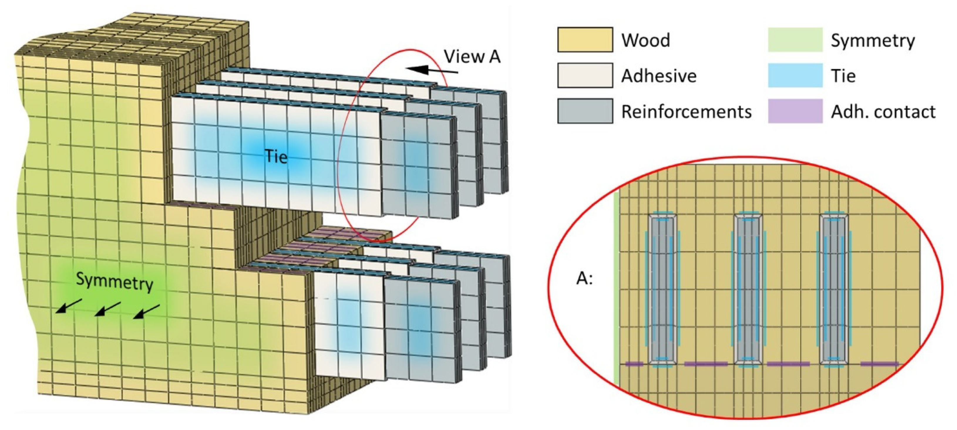
2.1.6. Model Geometry
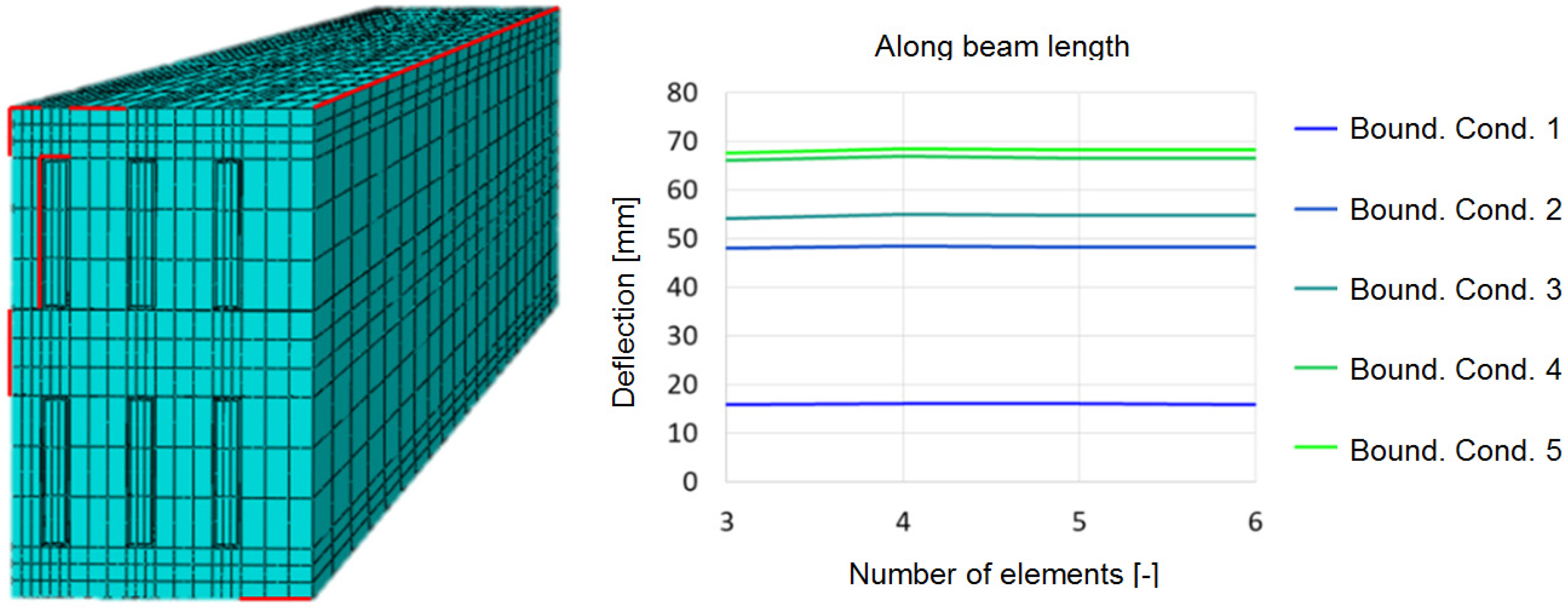
The presented model makes it possible to vary the geometry (with mesh and interactions) and optimise the reinforced, hybrid wooden beams for a specific load case. The geometry of each component of the reinforced hybrid wooden beam (i.e., timber, reinforcements, adhesive layer) is modelled independently. Figure 3 illustrates the hybrid composition of a reinforced wooden beam intended for a general description with this numerical model. The wooden layers are indicated with the ochre colour, while the grey colour represents the metal reinforcements. The model assumes that the wood and reinforcement domains are joined with a layer of adhesive whose thickness can be thick or thin, depending on the adhesion procedure.

2.1.7. Mesh

The geometries of the components are put in the structured meshes of the finite elements. The domains with isotropic and orthotropic material models are put in a mesh of hexaedric finite elements with quadratic interpolation and reduced integration (C3D20R type). Domains with cohesive material models (thick joints) are meshed with cohesive elements (COH3D8 type). In comparison with a non-structured mesh, a structured mesh gives more reliable results. It also makes it possible to thin the mesh in the directions of a monotone building, which can significantly reduce the time required for the calculation. The mesh thickness is defined along all the edges of the geometrical properties based on a convergence analysis, by means of which its negligible impact upon the model results is proved. An example is presented in Figure 4, where due to insignificant convergences a negligible impact upon the model results is established for all the checked mesh densities.

2.1.8. Interaction

Interactions link the models of different components into a physical whole. The following interaction types are foreseen: (i) connected surfaces; (ii) ideally stiff contact; (iii) very thin glued joint; and (iv) friction in the case of boundary conditions. It is necessary to connect the surfaces on the common surfaces of domains that lie next to each other and have to remain like that if they do not share common nodes. Such a phenomenon appears at the transition between the domain of isotropic and orthotropic materials and the cohesive domain with a thick joint (Figure 5). Although in this case the cohesive elements prevent the domains from overlapping, it is also recommended to prescribe an ideally stiff contact for the connected surfaces of non-cohesive domains (Figure 5). For very thin glued joints, the cohesive behaviour is prescribed in the form of a contact between the joined surfaces. The requirement of the ideally stiff contact and the friction between the surfaces can be used in some cases of requesting the boundary conditions of an analysis that no longer belongs to the description of a hybrid composite model.

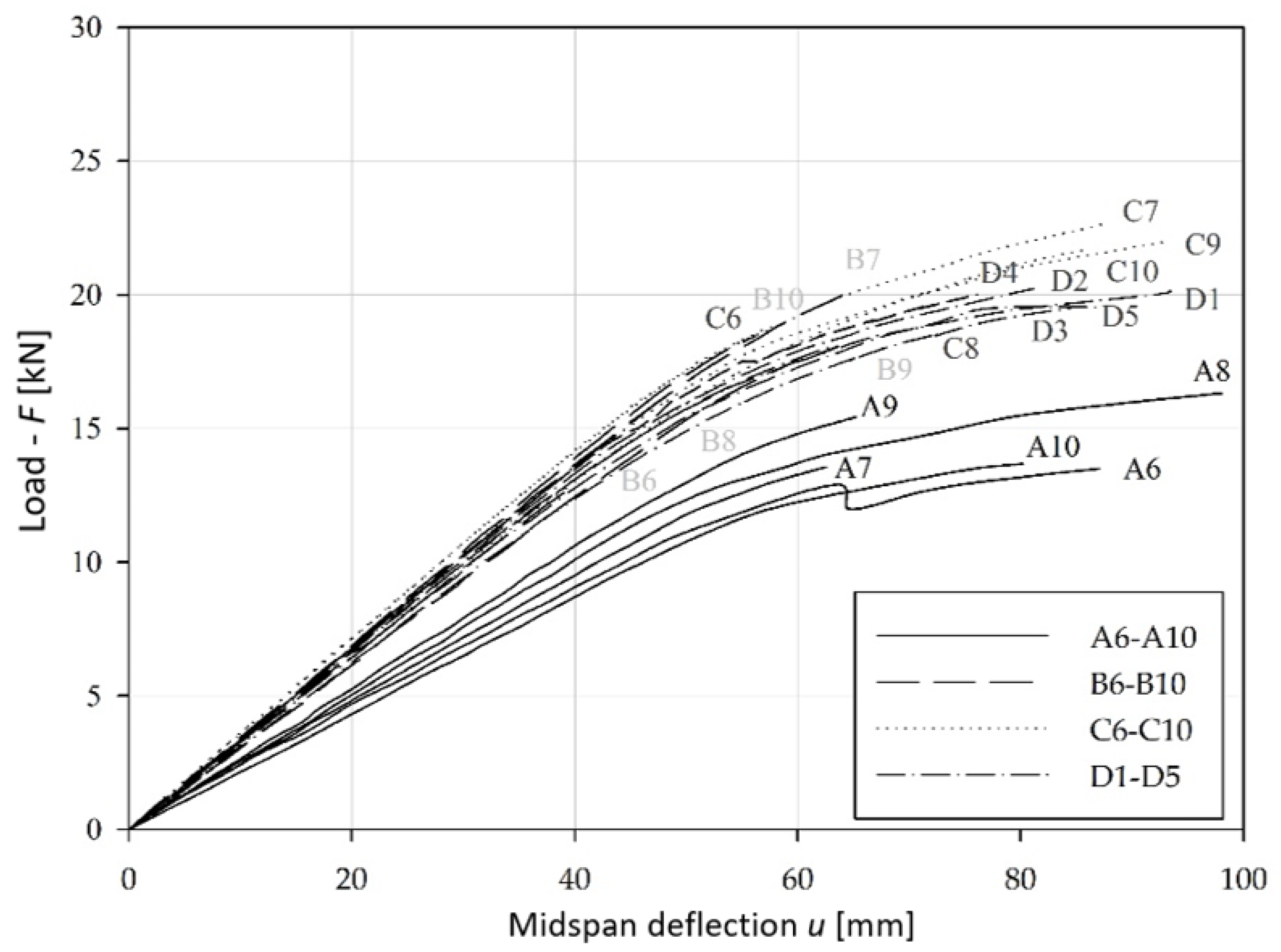
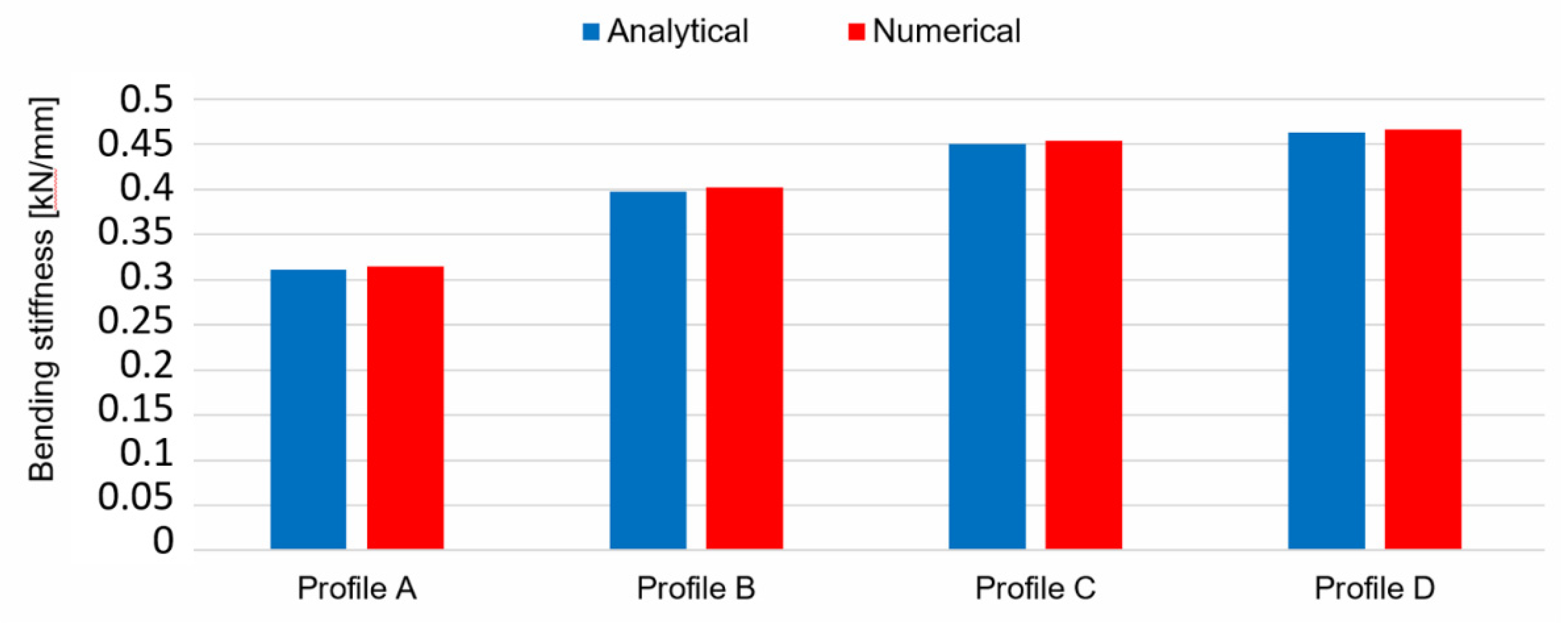
3. Results and Discussion

An experiment is needed for the validation of the model and/or the calibration of the model’s input parameters. The model was validated on the basis of previously obtained experimental results [44,45]. In this case, the four-point bending test was taken for the basis of the experiments and the simulation. Four cross-section variations (Figure 6), representing a preliminary frame-member design, were tested to evaluate their stiffness and to validate the performance of the computer model.
The four-point static bending tests, up to failure, were performed using a Roel Amsler HA 100 universal servo-hydraulic testing machine (Figure 7).
The flexural load was tested to the point of failure in displacement-control mode using an actuator velocity of 0.1 mm/s. Between both applied loads there was a constant bending moment, a zero-shear force, and the peak of the relative deflection was only the result of the bending moments. The deflections for every specimen were measured at two points with linear voltage-displacement transducers (LVDTs). These are indicated by IND in Figure 8.
The absolute deflection was the average of the those measured at the midspan (i.e., at IND 1 and IND 2 in Figure 8). The displacement, strain, and load were recorded with a data-acquisition system (Dewesoft DEWE 2500).
The deflection (u) at midspan was measured as a function of load (F) for all beam types (Figure 9). The angle of the linear part of the curves from the abscissa defines the bending stiffness. The larger the angle, the higher the bending stiffness. All experimental results have been published in previous research [44].
The numerical simulation fully simulates the experimental four-point bending test (Figure 10) in terms of the composite material’s properties, geometry, the interactions of domains and type of supports, and the loading.
In the numerical analysis, material data for the wood, aluminium, and glue were used as described in previous sections. Geometrically, four cross-sections were made (one without reinforcements and three with reinforcements, Figure 11) that precisely simulated the cross-sections of the experimentally tested supports (Figure 7 and Figure 8) of experiments carried out in previous research [44].
During the experiment [44] and also during the simulation, the largest deformation of the hybrid composite support was observed. Figure 12 presents the comparison between the numerical and experimental results [44]. The results match very well. Consequently, the model was validated to be used in comparable analyses.
For the area of the established linear dependency of the bendings of a hybrid support on the load, the bending stiffness of the support (ratio load/bending) was calculated on the basis of numerical results and also analytically [44] on the basis of adding the products between elasticity modules and the torque of single-component domains in the cross-section. Figure 13 presents a comparison between the numerically and analytically determined bending stiffnesses [44] of the composite support with four different reinforced cross-sections.
There is very good agreement between the numerical, analytical, and experimental results, as shown in Figure 14 in the load-deflection diagram (for Profile A). Similarly good correspondences can also be found for other profile types.
Consequently, the numerical model of the composite support is verified for use in comparable analyses.
Architectural trends favour open views through windows, with as few visible window frames as possible. Therefore, for this study, profiles with a small cross-section (i.e., slender) were analysed to explore the limits of improving their bending stiffness and strength when reinforced with stiffer materials. This investigation was an initial point for subsequent analyses that relate more to the reinforcements in window-element profiles. The Mullion profile (i.e., the middle window profile in a double-sashed window, Figure 15) combines a commonly used window profile and an element of a window that is most exposed to the load resulting from wind.
From the test data and numerical results, we can conclude that the best arrangement for reinforcement would be to combine the reinforcements for specimens of type C and type D. With reinforcements located in the tensile and compressive regions, the tensile and compressive strengths of the beams (e.g., the type-C specimens) can be increased. A vertically positioned reinforcement that covers most of the cross-sectional height (e.g., the type-D specimens) prevents shear failure before reaching the tensile and compressive stress limits. Figure 16 shows such a hybrid window beam.
In contrast, a vertical metal reinforcement that covers the height of the specimen can mean thermal transmission and thus lower the thermal efficiency of the window. In the worst case, it can cause a local reduction of the internal temperature, which could mean condensation followed by mould [46]. If the proper bending stiffness of the window elements could be achieved with aluminium reinforcements for the whole height of the profile, we would have a very cost-effective solution for manufacturing windows.
In subsequent numerical analyses with our developed model, the Mullion profile will be employed to set the highest-possible bending stiffness and load-bearing enhancements, while considering the material, orientation, position, and reinforcement.

4. Conclusions

The paper describes an experimentally validated numerical model of a hybrid beam that is a numerical platform for the optimisation of window-frame members.
  • A model based on computer simulations allows the prediction and analysis of the mechanical behaviour of a hybrid composite material consisting of several interconnected components made of different base materials.
  • The model includes the material and geometrical properties of the joints connecting the assembled components.
  • The model for different boundary conditions and parameters provides the correct data for stiffness, especially bending, and the maximum deformations.
  • The model allows for simulations of the elastic behaviour of hybrid wood–metal composites, while also enabling the prediction and observation of plastification onset and damage initiation.
  • The model enables parametrical simulations to find the optimal layout of reinforcements in the window-frame member, as well as the estimations of the maximum performance for a certain design.

Author Contributions

Conceptualisation, G.F.; methodology, A.K. and G.F.; validation, B.Š. and A.K; formal analysis, A.K.; investigation, A.K., G.F. and B.Š.; resources, G.F.; writing—original draft preparation, A.K. and G.F.; writing—review and editing, G.F.; visualisation, G.F.; supervision, G.F.; project administration, G.F. and B.Š.; funding acquisition, G.F. All authors have read and agreed to the published version of the manuscript.

Funding

The authors acknowledge the financial support of the Slovenian Research Agency (ARRS) within research program “Development Evaluation P2-0182” and by the European Regional Development Fund, European Commission [project TIGR4smart], grant number 5441-1/2016/116.

Institutional Review Board Statement

Not applicable.

Informed Consent Statement

Not applicable.

Data Availability Statement

Not applicable.

Conflicts of Interest

The authors declare no conflict of interest.

References

  1. Klöpffer, W. Life cycle assessment: From the beginning to the current state. Environ. Sci. Pollut. Res. Int. 1997, 4, 223–228. [Google Scholar] [CrossRef] [PubMed]
  2. Duinker, P.N.; Greig, L.A. Scenario analysis in environmental impact assessment: Improving explorations of the future. Environ. Impact Assess. Rev. 2007, 27, 206–219. [Google Scholar] [CrossRef]
  3. Plevris, N.; Triantafillou, T.C. FRP-Reinforced Wood as Structural Material. J. Mater. Civ. Eng. 1992, 4, 300–317. [Google Scholar] [CrossRef]
  4. Triantafillou, T.C.; Deskovic, N. Prestressed Frp Sheets as External Reinforcement of Wood Members. J. Struct. Eng. 1992, 118, 1270–1284. [Google Scholar] [CrossRef]
  5. Triantafillou, T.C. Shear reinforcement of wood using FRP materials. J. Mater. Civ. Eng. 1997, 9, 65–69. [Google Scholar] [CrossRef]
  6. Alhayek, H.; Svecova, D. Flexural Stiffness and Strength of GFRP-Reinforced Timber Beams. J. Compos. Constr. 2012, 16, 245–252. [Google Scholar] [CrossRef]
  7. Andor, K.; Lengyel, A.; Polgár, R.; Fodor, T.; Karácsonyi, Z. Experimental and statistical analysis of spruce timber beams reinforced with CFRP fabric. Constr. Build. Mater. 2015, 99, 200–207. [Google Scholar] [CrossRef]
  8. Nguyen Trung, V.A.; Le Roy, R.; Caron, J.-F. Multi-reinforcement of timber beams with composite materials: Experiments and fracture modeling. Compos. Struct. 2015, 123, 233–245. [Google Scholar] [CrossRef]
  9. Fiorelli, J.; Dias, A.A. Analysis of the strength and stiffness of timber beams reinforced with carbon fiber and glass fiber. Mater. Res. 2003, 6, 193–202. [Google Scholar] [CrossRef] [Green Version]
  10. Borri, A.; Corradi, M.; Grazini, A. A method for flexural reinforcement of old wood beams with CFRP materials. Compos. Part B Eng. 2005, 36, 143–153. [Google Scholar] [CrossRef]
  11. Miotto, J.L.; Dias, A.A. Structural efficiency of full-scale timber–concrete composite beams strengthened with fiberglass reinforced polymer. Compos. Struct. 2015, 128, 145–154. [Google Scholar] [CrossRef]
  12. Biscaia, H.; Chastre, C.; Cruz, D.; Franco, N. Flexural Strengthening of Old Timber Floors with Laminated Carbon Fiber–Reinforced Polymers. J. Compos. Constr. 2017, 21, 04016073. [Google Scholar] [CrossRef]
  13. Borri, A.; Corradi, M.; Speranzini, E. Reinforcement of wood with natural fibers. Compos. Part B Eng. 2013, 53, 1–8. [Google Scholar] [CrossRef] [Green Version]
  14. Ferrier, E.; Agbossou, A.; Michel, L. Mechanical behaviour of ultra-high-performance fibrous-concrete wood panels reinforced by FRP bars. Compos. Part B Eng. 2014, 60, 663–672. [Google Scholar] [CrossRef]
  15. Glišović, I.; Pavlovic, M.; Stevanovic, B.; Todorović, M. Numerical analysis of glulam beams reinforced with CFRP plates. J. Civ. Eng. Manag. 2017, 23, 868–879. [Google Scholar] [CrossRef] [Green Version]
  16. Hollaway, L.C.; Teng, J.G. Strengthening and Rehabilitation of Civil Infrastructures Using Fibre-Reinforced Polymer (FRP) Composites; CRC Press: Boca Raton, FL, USA, 2008. [Google Scholar]
  17. Yang, Y.-L.; Liu, J.-W.; Xiong, G. Flexural behavior of wood beams strengthened with HFRP. Constr. Build. Mater. 2013, 43, 118–124. [Google Scholar] [CrossRef]
  18. Mosallam, A.S. Structural evaluation and design procedure for wood beams repaired and retrofitted with FRP laminates and honeycomb sandwich panels. Compos. Part B Eng. 2016, 87, 196–213. [Google Scholar] [CrossRef] [Green Version]
  19. Corradi, M.; Borri, A.; Castori, G.; Speranzini, E. Fully reversible reinforcement of softwood beams with unbonded composite plates. Compos. Struct. 2016, 149, 54–68. [Google Scholar] [CrossRef] [Green Version]
  20. Smittakorn, W.; Heyliger, P.R. Adaptive Wood Composite: Experiment. J. Struct. Eng. 2003, 129, 699–702. [Google Scholar] [CrossRef]
  21. Fridley, K.J. Wood and Wood-Based Materials: Current Status and Future of a Structural Material. J. Mater. Civ. Eng. 2002, 14, 91–96. [Google Scholar] [CrossRef]
  22. De Jesus, A.M.T.; Pinto, J.J.L.; Morais, J. Analysis of solid wood beams strengthened with CFRP laminates of distinct lengths. Constr. Build. Mater. 2012, 35, 817–828. [Google Scholar] [CrossRef]
  23. Kim, J.Y.; Harries, K. Modeling of timber beams strengthened with various CFRP composites. Eng. Struct. 2010, 32, 3225–3234. [Google Scholar] [CrossRef]
  24. Nadir, Y.; Nagarajan, P.; Ameen, M.; Arif, M.M. Flexural stiffness and strength enhancement of horizontally glued laminated wood beams with GFRP and CFRP composite sheets. Constr. Build. Mater. 2016, 112, 547–555. [Google Scholar] [CrossRef]
  25. Schober, K.-U.; Harte, A.M.; Kliger, R.; Jockwer, R.; Xu, Q.; Chen, J.-F. FRP reinforcement of timber structures. Constr. Build. Mater. 2015, 97, 106–118. [Google Scholar] [CrossRef] [Green Version]
  26. Borri, A.; Corradi, M. Strengthening of timber beams with high strength steel cords. Compos. Part B Eng. 2011, 42, 1480–1491. [Google Scholar] [CrossRef]
  27. Jasieńko, J.; Nowak, T. Solid timber beams strengthened with steel plates—Experimental studies. Constr. Build. Mater. 2014, 63, 81–88. [Google Scholar] [CrossRef]
  28. Peterson, K.L.; Underhill, J.; Carlson, B.; Heyliger, P.R. The mechanics of plastic-aluminum composite I-beams. Compos. Struct. 2016, 136, 241–250. [Google Scholar] [CrossRef] [Green Version]
  29. Winter, W.; Tavoussi, K.; Pixner, T.; Parada, F.R. Timber-Steel-Hybrid Beams for Multi-Storey Buildings. In Proceedings of the World Conference on Timber Engineering 2012 (WCTE 2012), Auckland, New Zealand, 15–19 July 2012. [Google Scholar]
  30. Kretschmann, D.E. Mechanical Properties of Wood. In Wood Handbook: Wood as Engineering Material; Ross, R.J., Ed.; Forest Products Laboratory: Madison, WI, USA, 2010; pp. 501–546. [Google Scholar]
  31. Straze, A.; Fajdiga, G.; Pervan, S.; Gorisek, Z. Hygro-mechanical behavior of thermally treated beech subjected to compression loads. Constr. Build. Mater. 2016, 113, 28–33. [Google Scholar] [CrossRef]
  32. Fajdiga, G.; Zafosnik, B.; Gospodaric, B.; Straze, A. Compression Test of Thermally-Treated Beech Wood: Experimental and Numerical Analysis. Bioresources 2016, 11, 223–234. [Google Scholar] [CrossRef] [Green Version]
  33. Matthews, F.L. Introduction to Overview and review of composite materials. In Finite Element Modelling of Composite Materials and Structures; Matthews, F.L., Davies, G.A.O., Hitchings, D., Soutis, C., Eds.; Woodhead Publishing: Sawston, UK, 2000; p. 1. [Google Scholar]
  34. Valipour, H.R.; Crews, K. Efficient finite element modelling of timber beams strengthened with bonded fibre reinforced polymers. Constr. Build. Mater. 2011, 25, 3291–3300. [Google Scholar] [CrossRef]
  35. Oudjene, M.; Khelifa, M. Finite element modelling of wooden structures at large deformations and brittle failure prediction. Mater. Des. 2009, 30, 4081–4087. [Google Scholar] [CrossRef]
  36. Tran, T.T.; Thi, V.D.; Khelifa, M.; Oudjene, M.; Rogaume, Y. A constitutive numerical modelling of hybrid-based timber beams with partial composite action. Constr. Build. Mater. 2018, 178, 462–472. [Google Scholar] [CrossRef]
  37. SIMULIA. Abaqus Online Documentation, 6.14 ed. Dasault Systems. 2019. Available online: http://ivt-abaqusdoc.ivt.ntnu.no:2080/v6.14/index.html (accessed on 12 January 2021).
  38. Bodig, J.; Jayne, B. Mechanics of Wood and Wood Composites; Krieger Publishing: Malabar, FL, USA, 1993. [Google Scholar]
  39. Hill, R. A Theory of the Yielding and Plastic Flow of Anisotropic Metals. Proc. R. Soc. Lond. Ser. A 1948, 193, 281–297. [Google Scholar]
  40. Mckean, H.P.; Trubowitz, E. Hills Surfaces and Their Theta Functions. Bull. Am. Math. Soc. 1978, 84, 1042–1085. [Google Scholar] [CrossRef] [Green Version]
  41. Valliappan, S.; Boonlaulohr, P.; Lee, I.K. Non-linear analysis for anisotropic materials. Int. J. Numer. Methods Eng. 1976, 10, 597–606. [Google Scholar] [CrossRef]
  42. Chen, L.; Wen, W.; Cui, H. Generalization of Hill’s yield criterion to tension-compression asymmetry materials. Sci. China Technol. Sci. 2013, 56, 89–97. [Google Scholar] [CrossRef]
  43. Aboussafy, C.; Guilbault, R. Chip formation in machining of anisotropic plastic materials—A finite element modeling strategy applied to wood. Int. J. Adv. Manuf. Technol. 2021, 114, 1471–1486. [Google Scholar] [CrossRef]
  44. Šubic, B.; Fajdiga, G.; Lopatič, J. Bending Stiffness, Load-Bearing Capacity and Flexural Rigidity of Slender Hybrid Wood-Based Beams. Forests 2018, 9, 703. [Google Scholar] [CrossRef] [Green Version]
  45. Fajdiga, G.; Rajh, D.; Necemer, B.; Glodez, S.; Sraml, M. Experimental and Numerical Determination of the Mechanical Properties of Spruce Wood. Forests 2019, 10, 1140. [Google Scholar] [CrossRef] [Green Version]
  46. Šubic, B.; Ugovšek, A.; Starman, N.; Tatić, U.; Kovačič, A.; Fajdiga, G. Influence of glued-in reinforcement profiles on the thermal characteristics of wooden window profiles. Procedia Struct. Integr. 2018, 13, 503–510. [Google Scholar] [CrossRef]
Figure 1. Vertical member of a window with minimum support at its ends.
Forests 12 00918 g001
Figure 2. Definition of parameter envelope with an inverse-engineering approach.
Forests 12 00918 g002
Figure 3. Assembly of separate components (wooden parts, reinforcements, and adhesive layers) into a geometrical model of a hybrid wooden beam.
Forests 12 00918 g003
Figure 4. Example of a model with reinforced edges of geometrical properties, where the mesh density was checked with a convergence analysis (left) and an example of convergence analysis results for the mesh density along the reinforcement width (right).
Forests 12 00918 g004
Figure 5. Places in an example of a wooden hybrid composite model with glued reinforcements, as shown in Figure 3.
Forests 12 00918 g005
Figure 6. Cross-sections of type A, B, C, and D specimens.
Forests 12 00918 g006
Figure 7. Test equipment for the four-point bending tests.
Forests 12 00918 g007
Figure 8. Basic configuration of the test instrumentation.
Forests 12 00918 g008
Figure 9. Load–deflection relationship for A, B, C, and D profile.
Forests 12 00918 g009
Figure 10. Schematic presentation of a mechanical experiment (four-point bending test) with used boundary conditions and observed values.
Forests 12 00918 g010
Figure 11. Visualised simulation results for numerical models of hybrid composite supports with four different geometries of the cross-section (from left to right: A, B, C, and D).
Forests 12 00918 g011
Figure 12. Comparison of numerical and experimental results for a four-point bending test of a reinforced composite support.
Forests 12 00918 g012
Figure 13. Comparison of numerically and analytically determined bending stiffnesses of a reinforced composite support.
Forests 12 00918 g013
Figure 14. Load-deflection relationship (Profile A).
Forests 12 00918 g014
Figure 15. Mullion—middle fixed element of the double sashed window.
Forests 12 00918 g015
Figure 16. Example of a window profile with horizontally and vertically positioned reinforcements.
Forests 12 00918 g016
Table 1. Material parameters of aluminium.
ParameterValueUnit
E71,000N/mm2
ν 0.33-
σ ¯ 160N/mm2
Table 2. Material parameters of steel.
ParameterValueUnit
E210,000N/mm2
ν 0.3-
σ ¯ 275N/mm2
Table 3. Material parameters of spruce wood.
ParameterValueUnit
E 1   14,460 *N/mm2
E 2 900N/mm2
E 3 470N/mm2
ν 12 0.37-
ν 13 0.46-
ν 23 0.44-
G 12 880N/mm2
G 13 882N/mm2
G 23 43N/mm2
σ ¯ 11 43 *N/mm2
σ ¯ 22 1.3 *N/mm2
σ ¯ 33 1.3 *N/mm2
σ ¯ 12 5.2 *N/mm2
σ ¯ 13 5.2 *N/mm2
σ ¯ 23 5.2 *N/mm2
* Indicates that the values were defined with a calibration.
Table 4. Material parameters of adhesive.
ParameterValueUnit
K n n   or   E n n / T 0   200N/mm3
K s s   or   E s s / T 0   200N/mm3
K t t   or   E t t / T 0   200N/mm3
t ¯ n 1.3N/mm2
t ¯ s 5.2N/mm2
t ¯ t 5.2N/mm2
Publisher’s Note: MDPI stays neutral with regard to jurisdictional claims in published maps and institutional affiliations.

