
Improvement in Microstructure and Properties of 304 Steel Wire Arc Additive Manufacturing by the Micro-Control Deposition Trajectory
Abstract
:1. Introduction
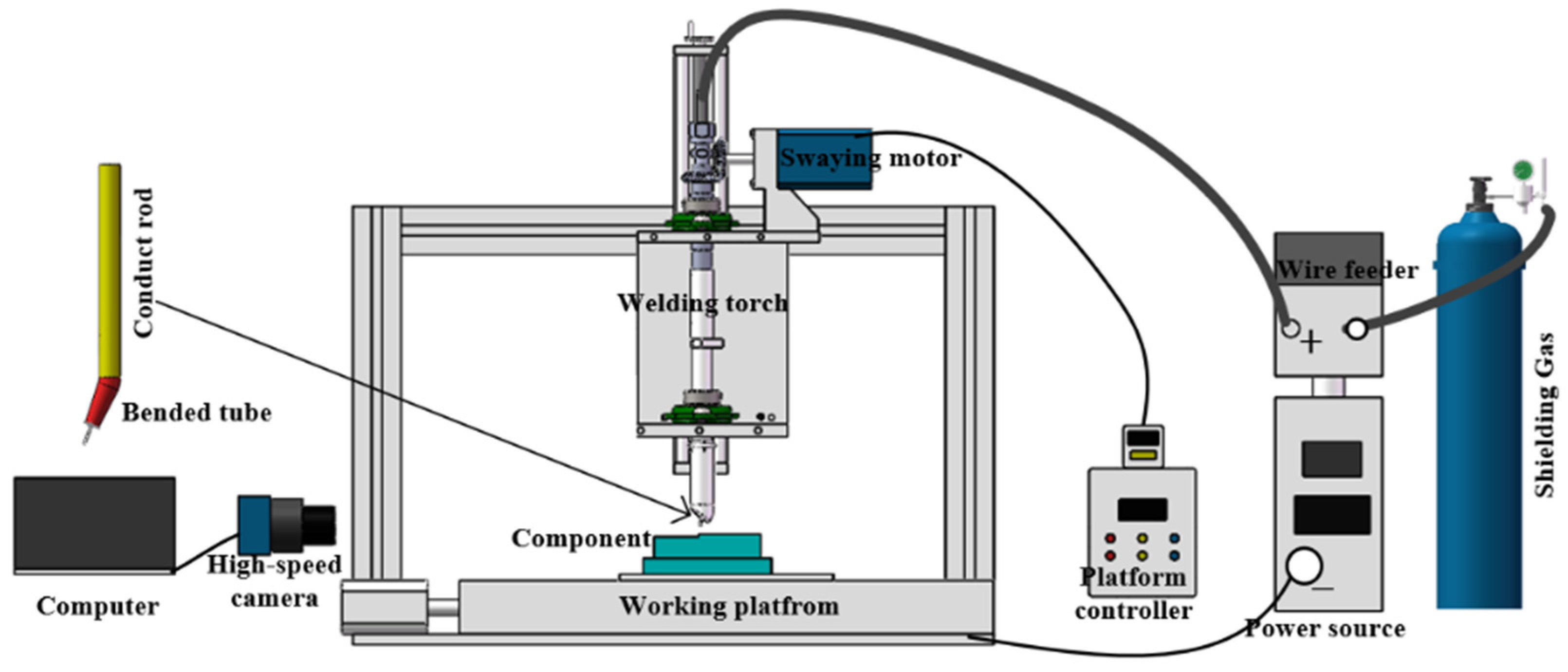
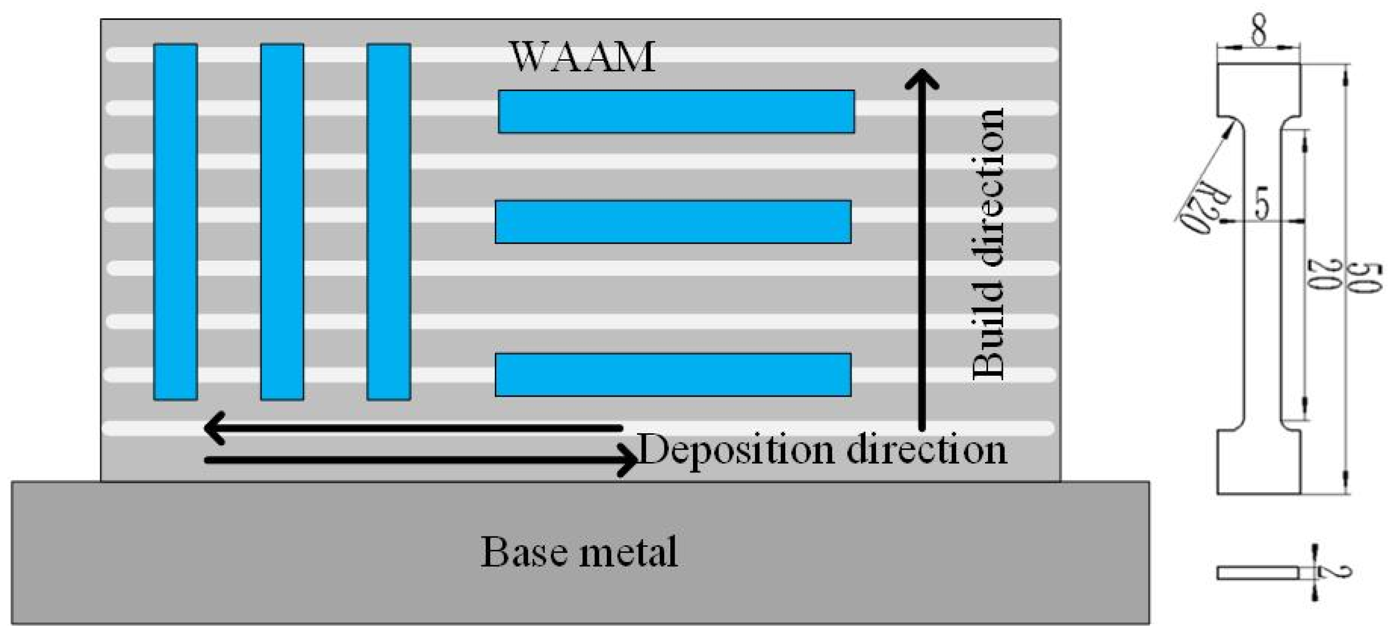
2. Materials and Methods
3. Results and Discussions
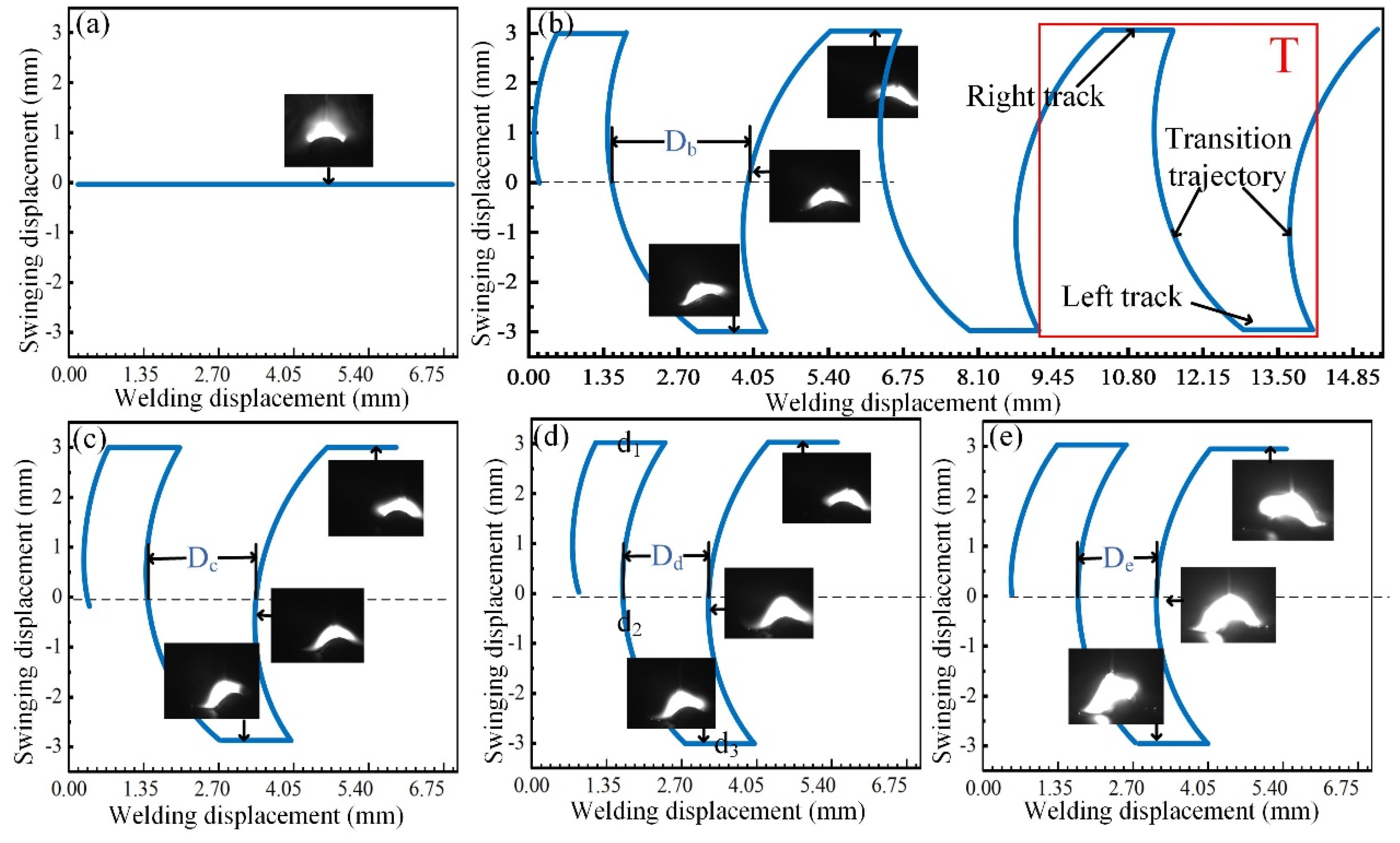
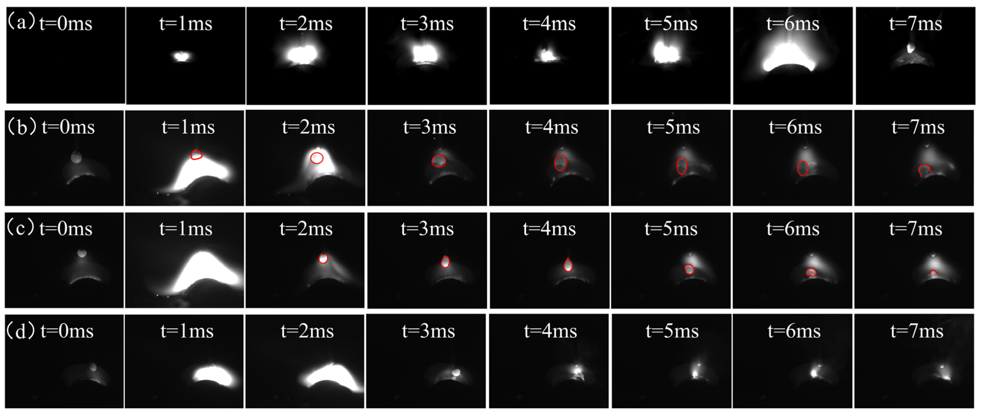
3.1. Arc Characteristics
3.2. Appearance and Microstructure of Thin-Walled Component
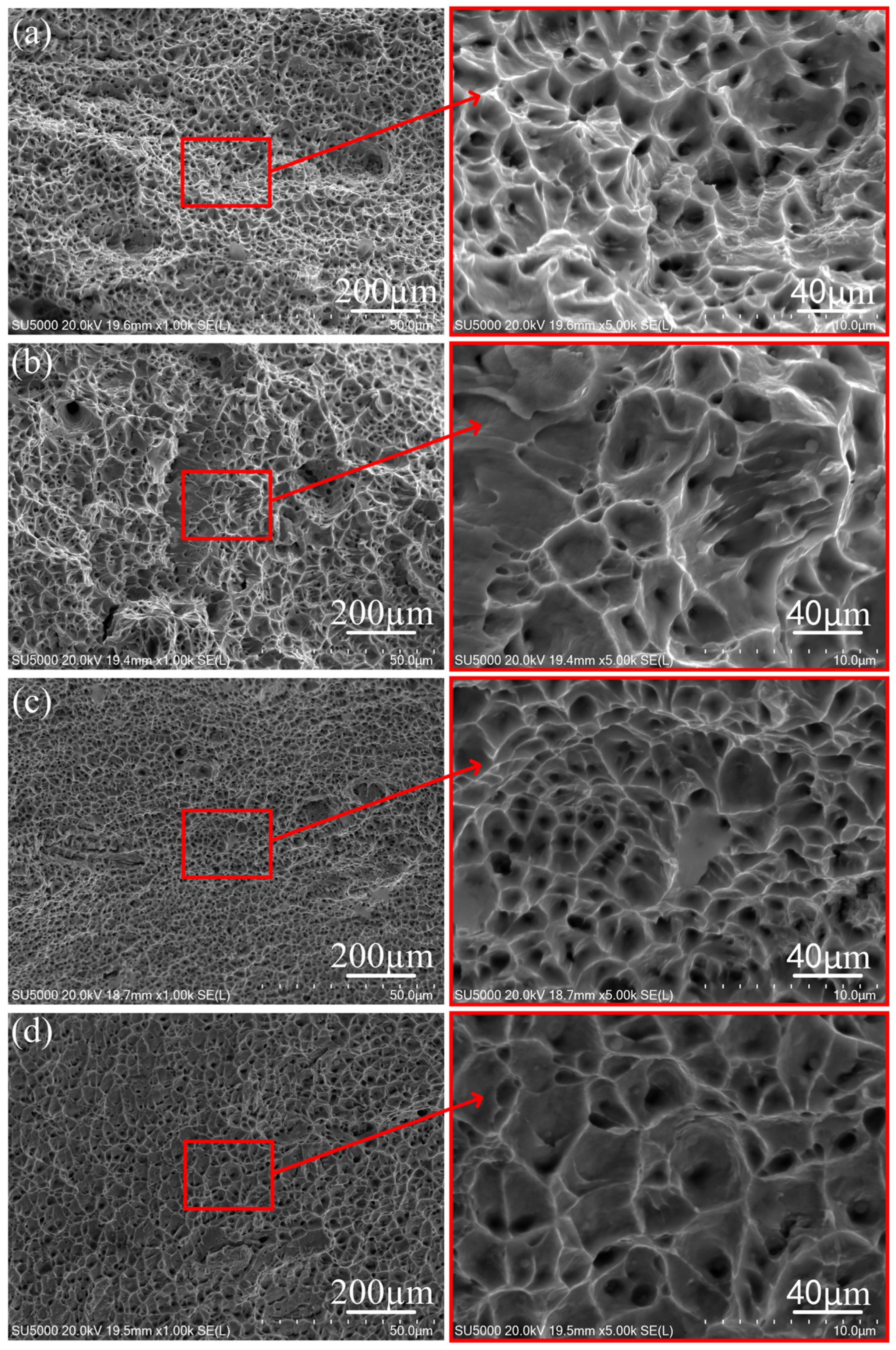
3.3. Mechanical Behavior of the Thin-Walled Component
4. Conclusions
- The micro-control deposition trajectory technology disperses the arc force and evenly heats the deposited layer. When the swing rate is too high, the centrifugal force of the arc is too large, resulting in an unstable arc and large splash. In the common deposition, the transition form of the droplet is the short circuit transition. The molten pool is affected by vertically downward arc pressure and droplet impact, resulting in a deeper middle and the shallower sides of the molten pool, while the micro-control deposition trajectory is affected by the deposition path and swing speed. The transition form of the droplet is the droplet transition. The micro-control deposition trajectory technology has achieved a relatively uniform melting depth and increased the stirring effect of the molten pool;
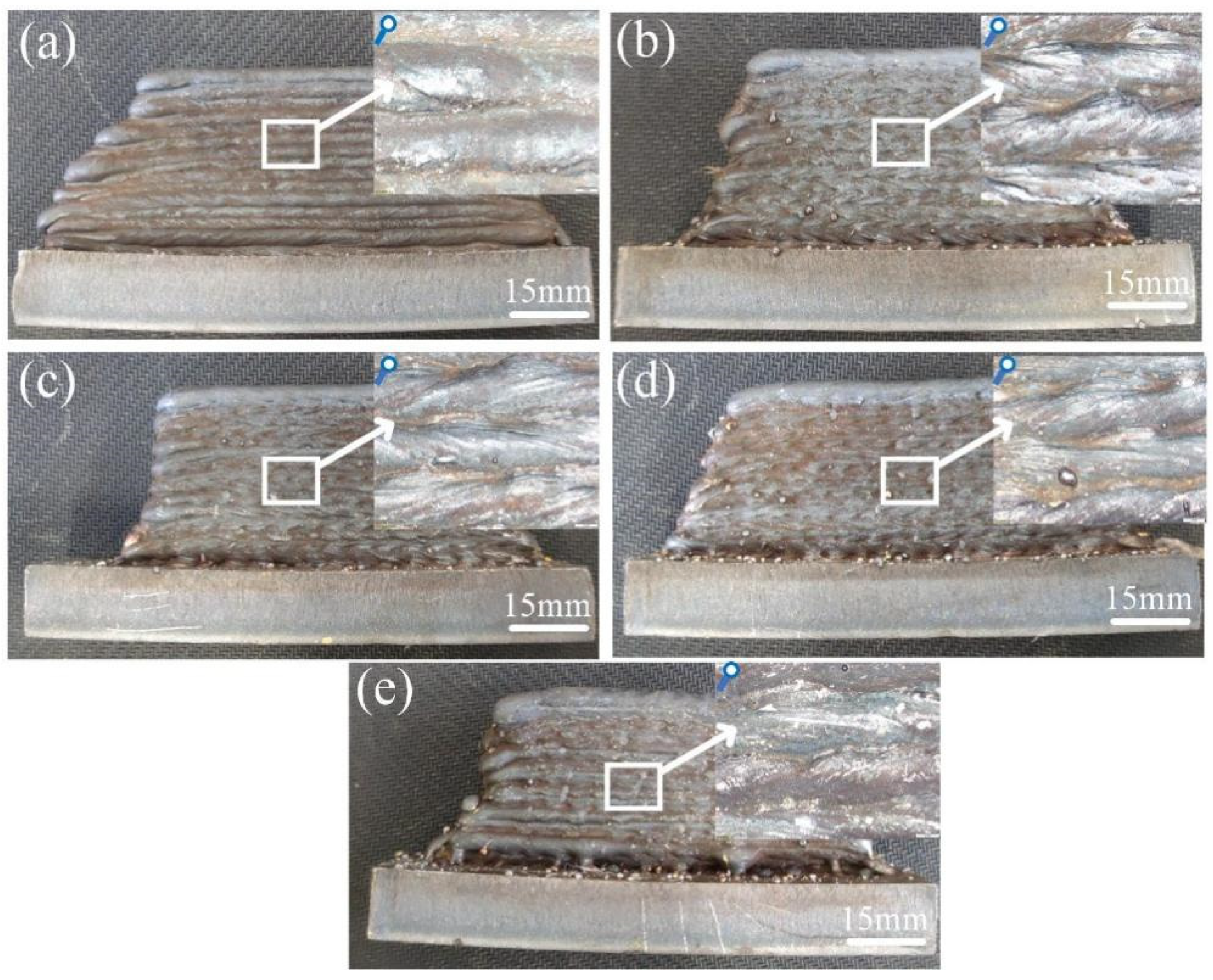
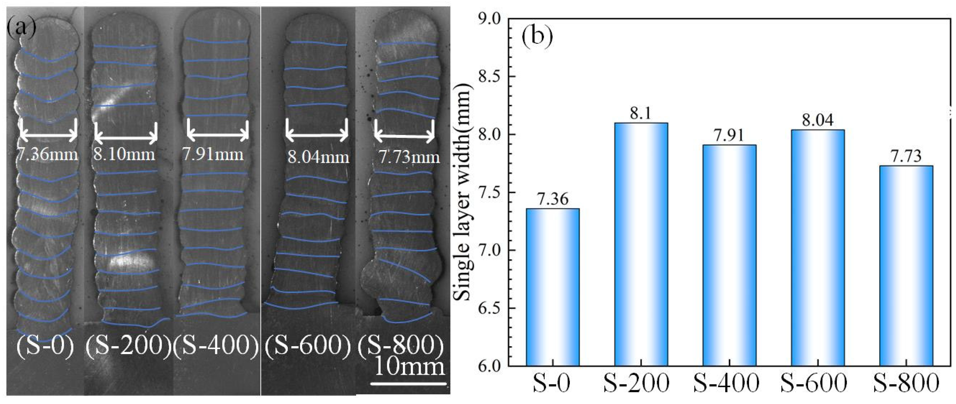
- There is no obvious defect in the micro-control thin-walled deposition components. The cross-section fusion line of the common thin-walled deposition components is a concave arc. The transverse fusion line of the micro-control thin-walled deposition components is horizontal and the melting depth is more uniform;
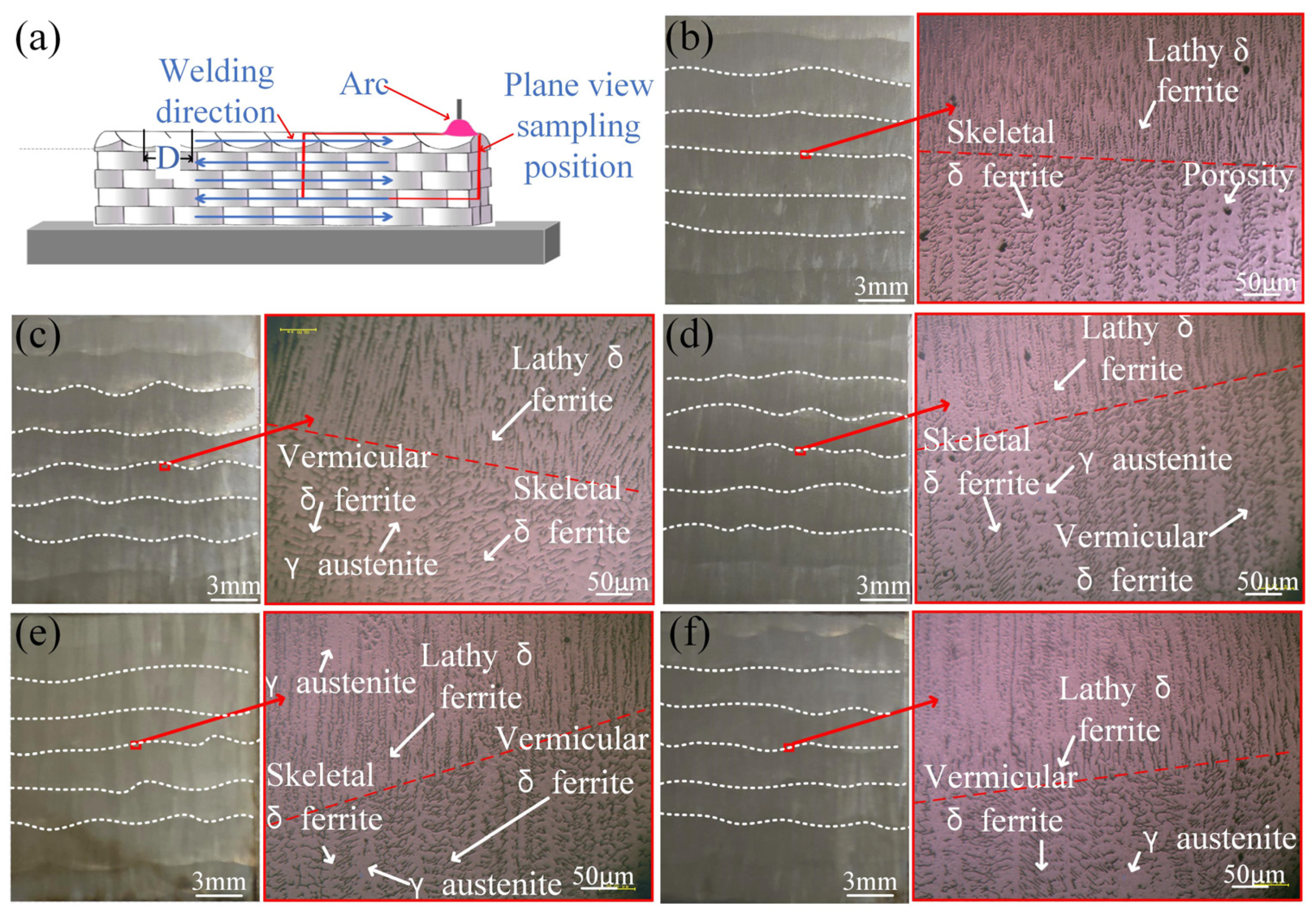
- With the increase in the swing rate, the proportion of transition trajectory stages in the period decreases. Below the interface of the deposition layer, the microstructure of the common thin-walled deposition components and the micro-control thin-walled deposition components is composed of lathy ferrite and austenite. Compared with the common deposition, when the swing speed increased to 800 °/s, the microstructure consisted of vermicular ferrite and austenite;
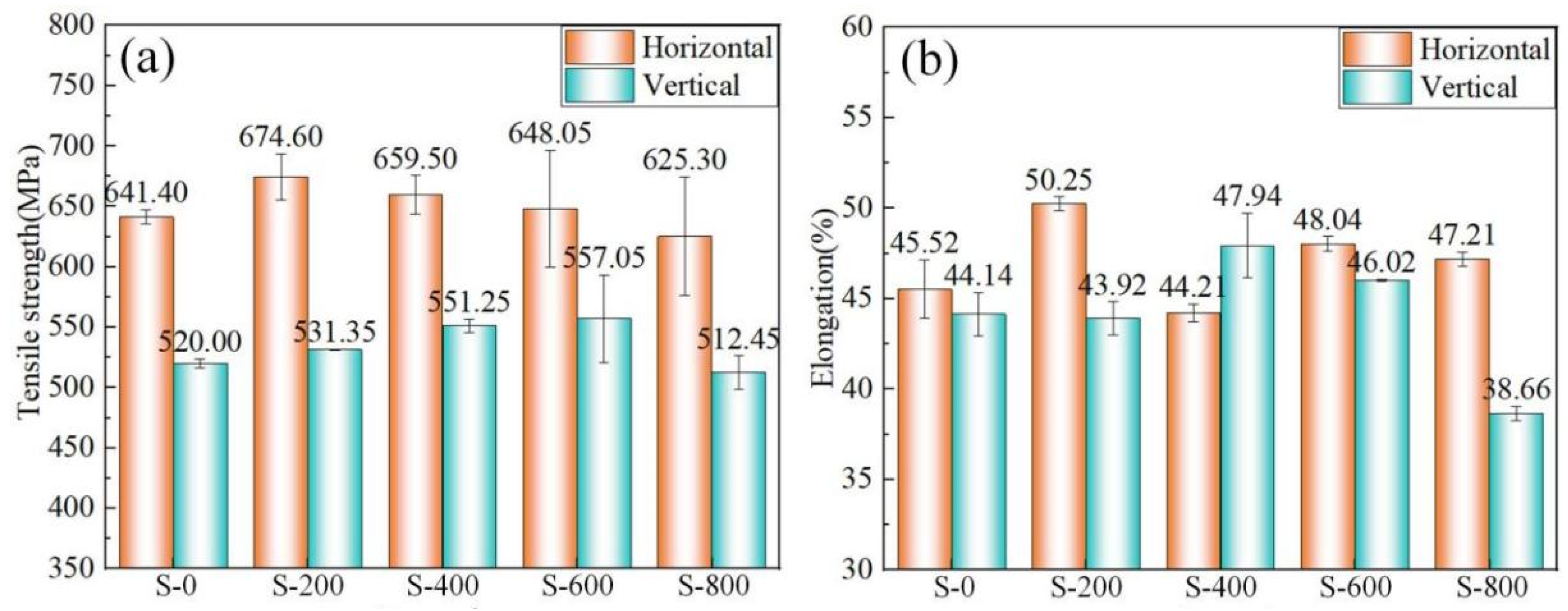
- The tensile strength and elongation of the micro-control thin-walled deposition components are higher than those of the common thin-walled deposition components. The tensile fracture mechanism of the common deposition and the micro-control deposition is the ductile fracture mechanism. There are a lot of dimples and tear edges in the fracture. Compared with the micro-control thin-walled deposition components, there are porosity defects in the common thin-walled deposition components.
Author Contributions
Funding
Institutional Review Board Statement
Informed Consent Statement
Data Availability Statement
Conflicts of Interest
References
- Hosseini, V.A.; Högström, M.; Hurtig, K.; Bermejo, M.A.V.; Stridh, L.-E.; Karlsson, L. Wire-arc additive manufacturing of a duplex stainless steel: Thermal cycle analysis and microstructure characterization. Weld. World 2019, 63, 975–987. [Google Scholar] [CrossRef]
- Chen, C.; Chen, F.; Yang, Y.; Zhang, H. Study on appearance and mechanical behavior of additively manufacturing of Ti–6Al–4V alloy by using cold metal transfer. CIRP J. Manuf. Sci. Technol. 2021, 35, 250–258. [Google Scholar] [CrossRef]
- Roy, S.; Silwal, B.; Nycz, A.; Noakes, M.; Cakmak, E.; Nandwana, P.; Yamamoto, Y. Investigating the effect of different shielding gas mixtures on microstructure and mechanical properties of 410 stainless steel fabricated via large scale additive manufacturing. Addit. Manuf. 2021, 38, 101821. [Google Scholar] [CrossRef]
- Elmer, J.W.; Fisher, K.; Gibbs, G.; Sengthay, J.; Urabe, D. Post-build thermomechanical processing of wire arc additively manufactured stainless steel for improved mechanical properties and reduction of crystallographic texture. Addit. Manuf. 2022, 50, 102573. [Google Scholar] [CrossRef]
- Sood, A.; Schimmel, J.; Ferreira, V.M.; Bosman, M.; Goulas, C.; Popovich, V.; Hermans, M.J. Directed energy deposition of Invar 36 alloy using cold wire pulsed gas tungsten arc welding: Effect of heat input on the microstructure and functional behaviour. J. Mater. Res. Technol. 2023, 25, 6183–6197. [Google Scholar] [CrossRef]
- Aldalur, E.; Suárez, A.; Veiga, F. Metal transfer modes for Wire Arc Additive Manufacturing Al-Mg alloys: Influence of heat input in microstructure and porosity. J. Mater. Process. Technol. 2021, 297, 117271. [Google Scholar] [CrossRef]
- Jing, C.; Chen, Z.; Liu, B.; Xu, T.; Wang, J.; Lu, T.; Lu, J.; Guo, Y.; Liu, C. Improving mechanical strength and isotropy for wire-arc additive manufactured 304L stainless steels via controlling arc heat input. Mater. Sci. Eng. A 2022, 845, 143223. [Google Scholar] [CrossRef]
- Kim, S.-G.; Lee, C.-M.; Kim, D.-H. Plasma-assisted machining characteristics of wire arc additive manufactured stainless steel with different deposition directions. J. Mater. Res. Technol. 2021, 15, 3016–3027. [Google Scholar] [CrossRef]
- Rani, K.U.; Kumar, R.; Mahapatra, M.M.; Mulik, R.S.; Świerczyńska, A.; Fydrych, D.; Pandey, C. Wire Arc Additive Manufactured Mild Steel and Austenitic Stainless Steel Components: Microstructure, Mechanical Properties and Residual Stresses. Materials 2022, 15, 7094. [Google Scholar] [CrossRef] [PubMed]
- Tomar, B.; Shiva, S. Microstructure evolution in steel/copper graded deposition prepared using wire arc additive manufacturing. Mater. Lett. 2022, 328, 133217. [Google Scholar] [CrossRef]
- Nemani, A.V.; Ghaffari, M.; Salahi, S.; Lunde, J.; Nasiri, A. Effect of interpass temperature on the formation of retained austenite in a wire arc additive manufactured ER420 martensitic stainless steel. Mater. Chem. Phys. 2021, 266, 124555. [Google Scholar] [CrossRef]
- Wang, L.; Xue, J.; Wang, Q. Correlation between arc mode, microstructure, and mechanical properties during wire arc additive manufacturing of 316 L stainless steel. Mater. Sci. Eng. A 2019, 751, 183–190. [Google Scholar] [CrossRef]
- Sealy, M.P.; Karunakaran, R.; Ortgies, S.; Madireddy, G.; Malshe, A.P.; Rajurkar, K.P. Reducing corrosion of additive manufactured magnesium alloys by interlayer ultrasonic peening. CIRP Ann. 2021, 70, 179–182. [Google Scholar] [CrossRef]
- Zhang, H.; Huang, J.; Liu, C.; Ma, Y.; Han, Y.; Xu, T.; Lu, J.; Fang, H. Fabricating Pyramidal Lattice Structures of 304 L Stainless Steel by Wire Arc Additive Manufacturing. Materials 2020, 13, 3482. [Google Scholar] [CrossRef] [PubMed]
- Bhattacharya, A.; Bera, T.K.; Suri, V.K. Influence of Heat Input in Automatic GMAW: Penetration Prediction and Microstructural Observation. Mater. Manuf. Process. 2014, 29, 1210–1218. [Google Scholar] [CrossRef]
- Corradi, D.R.; Bracarense, A.Q.; Wu, B.; Cuiuri, D.; Pan, Z.; Li, H. Effect of Magnetic Arc Oscillation on the geometry of single-pass multi-layer walls and the process stability in wire and arc additive manufacturing. J. Am. Acad. Dermatol. 2020, 283, 116723. [Google Scholar] [CrossRef]
- Wang, L.; Gao, M.; Zhang, C.; Zeng, X. Effect of beam oscillating pattern on weld characterization of laser welding of AA6061-T6 aluminum alloy. Mater. Des. 2016, 108, 707–717. [Google Scholar] [CrossRef]
- Yuan, T.; Luo, Z.; Kou, S. Grain refining of magnesium welds by arc oscillation. Acta Mater. 2016, 116, 166–176. [Google Scholar] [CrossRef]
- Guo, N.; Lin, S.B.; Zhang, L.; Yang, C.L. Metal transfer characteristics of rotating arc narrow gap horizontal GMAW. Sci. Technol. Weld. Join. 2009, 14, 760–764. [Google Scholar] [CrossRef]
- Yang, C.L.; Guo, N.; Lin, S.B.; Fan, C.L.; Zhang, Y.Q. Application of rotating arc system to horizontal narrow gap welding. Sci. Technol. Weld. Join. 2013, 14, 172–177. [Google Scholar] [CrossRef]
- Chen, Y.; Sun, X.; Zhang, T.; Li, Q.; Ni, S.; Fang, C. Arc rotating behavior of SRA EGW in AH36 steel. Mater. Manuf. Process. 2020, 35, 556–563. [Google Scholar] [CrossRef]
- Hassler, M.; Rose, S.; Fussel, U. TIG narrow gap welding—New approaches to evaluate and improve the shielding gas coverage and the energy input. Weld. World 2015, 59, 71–76. [Google Scholar] [CrossRef]
- Guo, N.; Wang, M.R.; Guo, W.; Yu, J.B.; Feng, J.C. Effect of rotating arc process on molten pool control in horizontal welding. Sci. Technol. Weld. Join. 2014, 19, 385–391. [Google Scholar] [CrossRef]
- Guo, N.; Wang, M.; Guo, W.; Yu, J.; Feng, J. Study on forming mechanism of appearance defects in rotating arc narrow gap horizontal GMAW. Int. J. Adv. Manuf. Technol. 2014, 75, 15–20. [Google Scholar] [CrossRef]
- Mirshekari, G.; Tavakoli, E.; Atapour, M.; Sadeghian, B. Microstructure and corrosion behavior of multipass gas tungsten arc welded 304L stainless steel. Mater. Des. 2014, 55, 905–911. [Google Scholar] [CrossRef]
- Sridhar, P.V.S.S.; Biswas, P.; Mahanta, P. Effect of process parameters on bead geometry, tensile and microstructural properties of double-sided butt submerged arc welding of SS 304 austenitic stainless steel. J. Braz. Soc. Mech. Sci. Eng. 2020, 42, 551. [Google Scholar] [CrossRef]
- Cai, X.Y.; Fan, C.L.; Lin, S.B.; Yang, C.L.; Bai, J.Y. Molten pool behaviors and weld forming characteristics of all-position tandem narrow gap GMAW. Int. J. Adv. Manuf. Technol. 2016, 87, 2437–2444. [Google Scholar] [CrossRef]
- Wei, B.; Jia, C.; Wu, W.; Fang, C.; Wu, C. Stirring effect of the rotating arc on the molten pool during non-axisymmetric tungsten NG-GTAW. J. Mater. Process. Technol. 2020, 285, 116769. [Google Scholar] [CrossRef]
- Cui, H.C.; Jiang, Z.D.; Tang, X.H.; Lu, F.G. Research on narrow-gap GMAW with swing arc system in horizontal position. Int. J. Adv. Manuf. Technol. 2014, 74, 297–305. [Google Scholar] [CrossRef]
- Yu, P.; Thompson, K.J.; McCarthy, J.; Kou, S. Microstructure Evolution and Solidification Cracking in Austenitic Stainless Steel Welds. Weld. J. 2018, 97, 301–314. [Google Scholar]


| Materials | C | Si | Mn | P | S | Ni | Cr |
|---|---|---|---|---|---|---|---|
| Base material | ≤0.08 | ≤1.00 | ≤2.00 | ≤0.035 | 0.03 | 8.00–11.00 | 17.00–19.00 |
| Steel wire | 0.05 | 0.44 | 1.43 | 0.03 | 0.01 | 8.08 | 18.08 |
| Specimen | Swing Speed (°/s) | Frequency (Hz) | D (mm) |
|---|---|---|---|
| S−0 | 0 | 0 | 0 |
| S−200 | 200 | 0.83 | 2.685 |
| S−400 | 400 | 1.11 | 2.100 |
| S−600 | 600 | 1.33 | 1.637 |
| S−800 | 800 | 1.48 | 1.522 |
Disclaimer/Publisher’s Note: The statements, opinions and data contained in all publications are solely those of the individual author(s) and contributor(s) and not of MDPI and/or the editor(s). MDPI and/or the editor(s) disclaim responsibility for any injury to people or property resulting from any ideas, methods, instructions or products referred to in the content. |
© 2024 by the authors. Licensee MDPI, Basel, Switzerland. This article is an open access article distributed under the terms and conditions of the Creative Commons Attribution (CC BY) license (https://creativecommons.org/licenses/by/4.0/).
Share and Cite
Zhang, H.; Liu, W.; Zhao, X.; Zhang, X.; Chen, C. Improvement in Microstructure and Properties of 304 Steel Wire Arc Additive Manufacturing by the Micro-Control Deposition Trajectory. Materials 2024, 17, 1170. https://doi.org/10.3390/ma17051170
Zhang H, Liu W, Zhao X, Zhang X, Chen C. Improvement in Microstructure and Properties of 304 Steel Wire Arc Additive Manufacturing by the Micro-Control Deposition Trajectory. Materials. 2024; 17(5):1170. https://doi.org/10.3390/ma17051170
Chicago/Turabian StyleZhang, Huijing, Weihang Liu, Xiaohui Zhao, Xinlong Zhang, and Chao Chen. 2024. "Improvement in Microstructure and Properties of 304 Steel Wire Arc Additive Manufacturing by the Micro-Control Deposition Trajectory" Materials 17, no. 5: 1170. https://doi.org/10.3390/ma17051170