
Study on the Mechanical Properties of Two General-Purpose Cement–Lime Mortars Prepared Based on Air Lime

Abstract
:1. Introduction
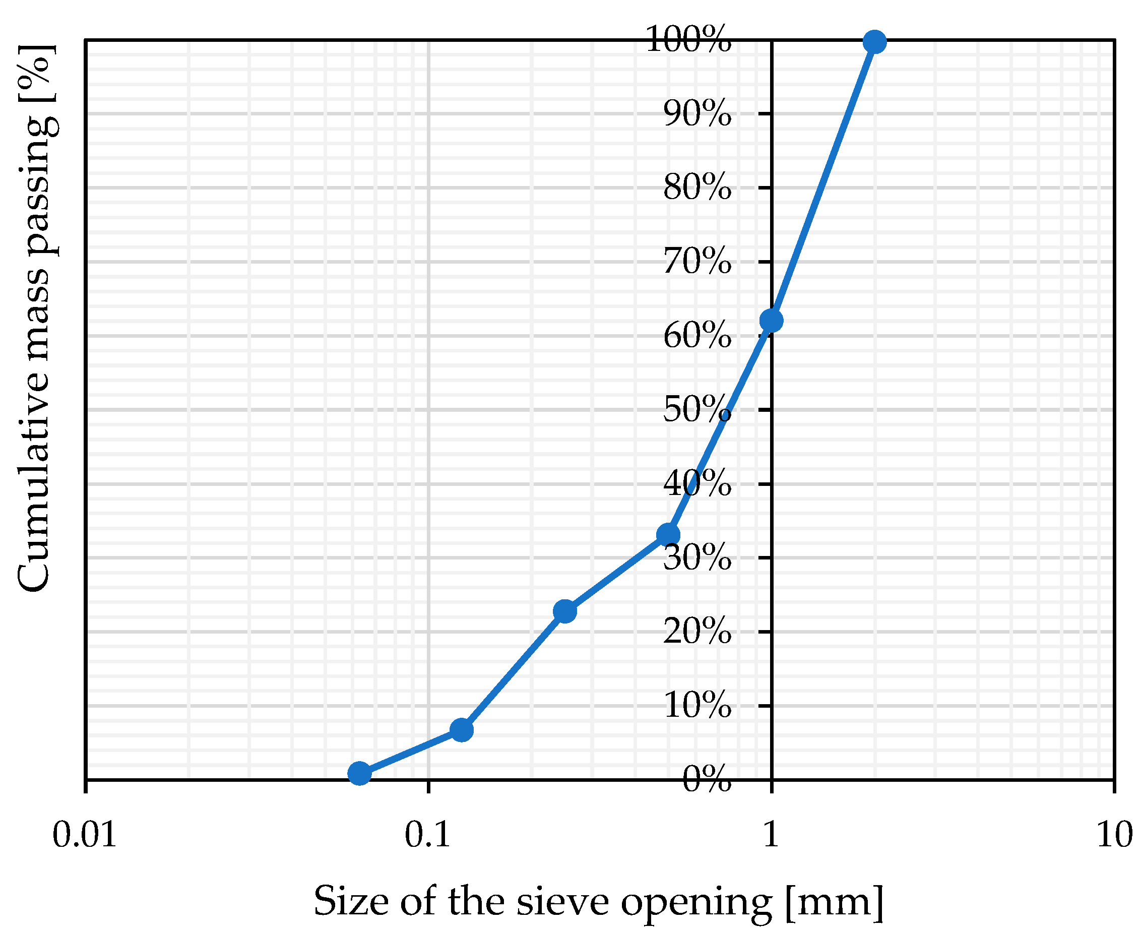
2. Materials
3. Methods and Test Set-Up Details
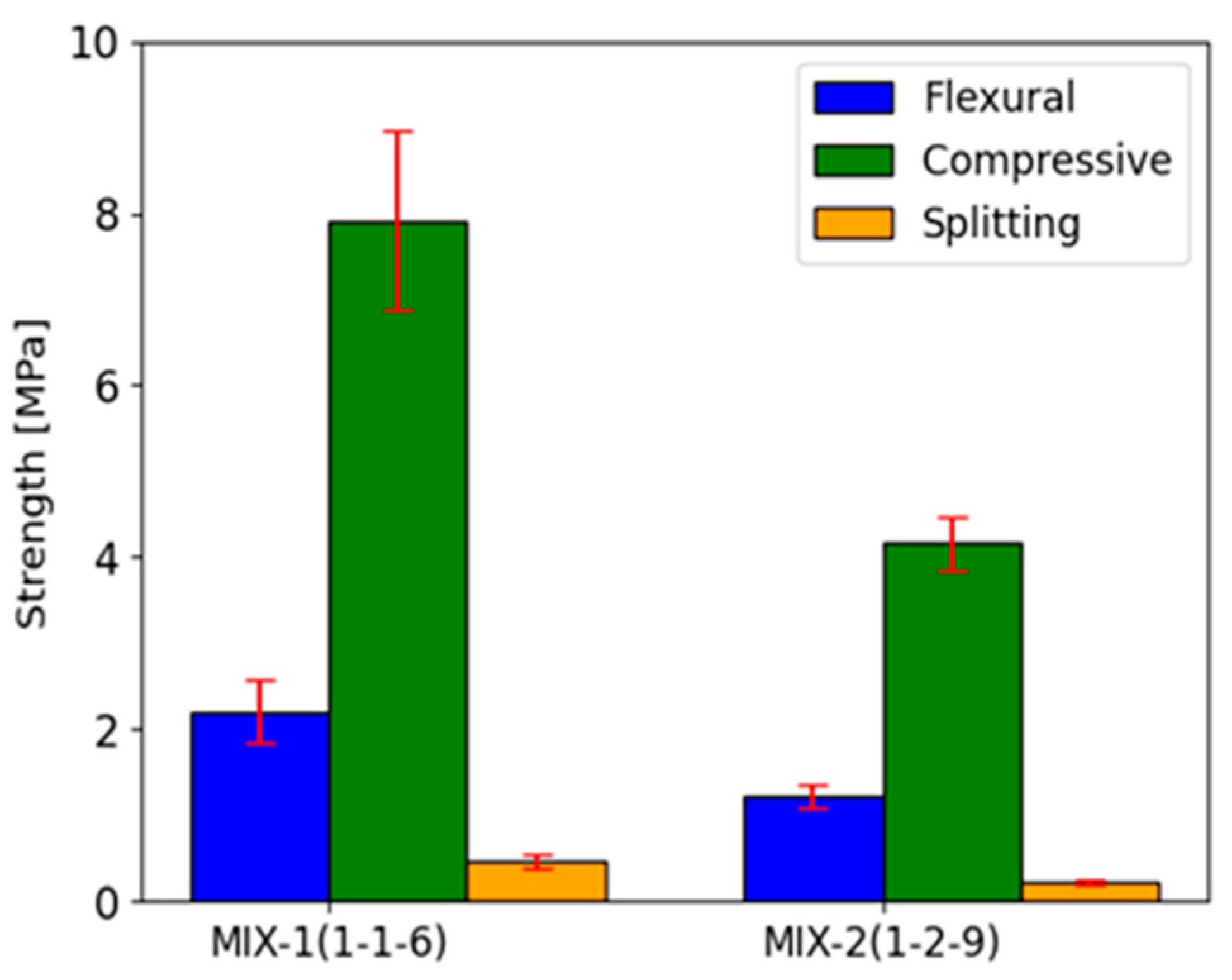
3.1. Flexural and Compressive Strength on the Basis of EN 1015-11 [54]
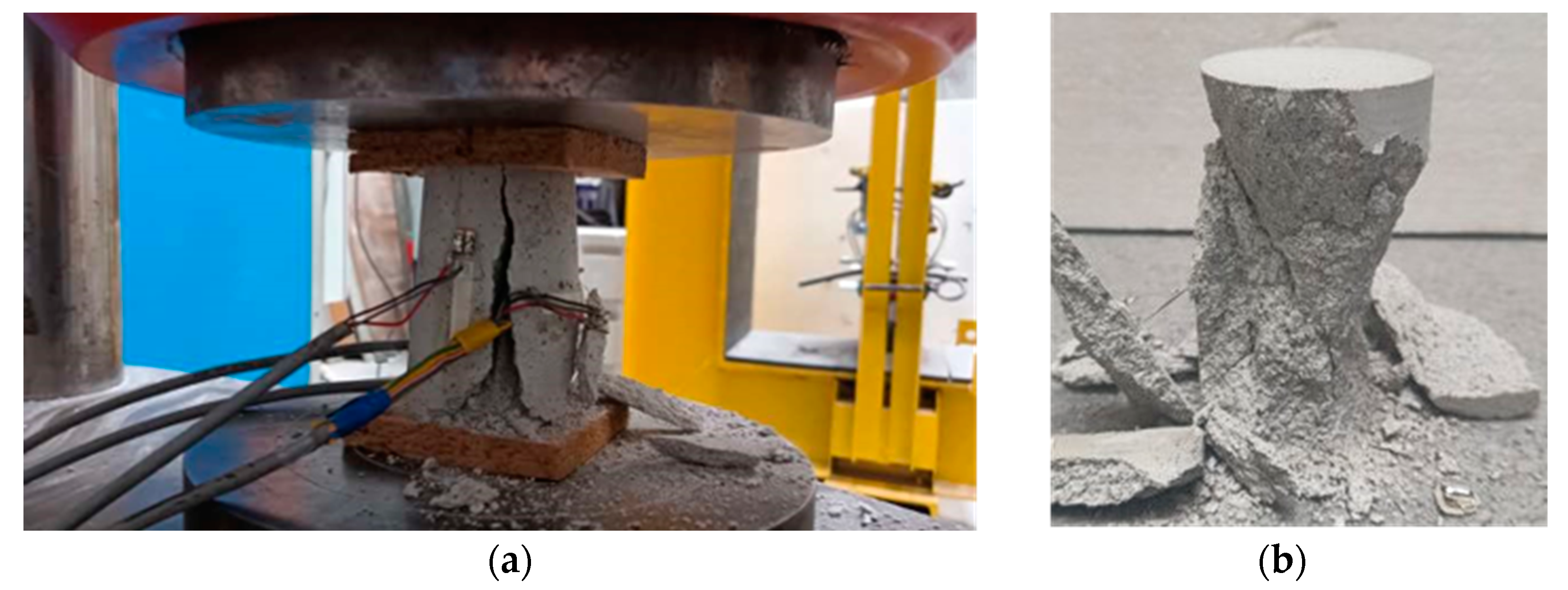
3.2. Compressive Strength and Stress–Strain Relationship on the Basis of the Cylinder Specimens Test
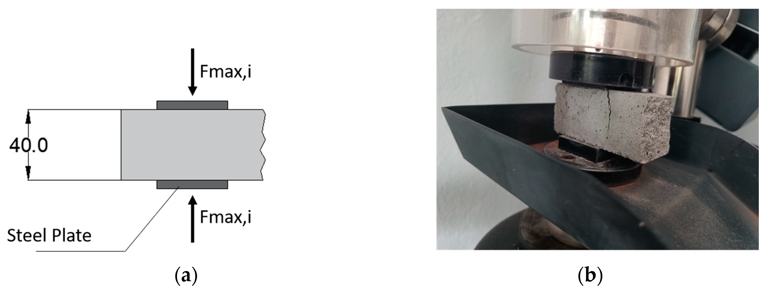
3.3. Tensile Strength on the Basis of ASTM C496 [56]
3.4. Fracture Energy Test
4. Test Results
- -
- for MIX-1 mortar: fcc/fc = 0.49;
- -
- for MIX-2 mortar: fcc/fc = 0.45.
5. Discussion
6. Conclusions
- Mortars with a higher content of lime in the binder show a deterioration in their mechanical properties, with the exception of ductility and Poisson’s ratio. As a result, the material is softer but can withstand greater deformation and expansion, which can be seen as a positive aspect (reduction of cracks) in masonry structures. In the presented tests, the compressive strength of the mortar with the ingredient ratio of 1:1:6 (MIX-1) was almost higher than that obtained for the mortar 1:2:9 (MIX-2);
- Analyzing the dependencies involving the ratios of standard compressive, flexural, and split-cylinder tensile strength, a more pronounced decline is evident for compressive and tensile strength compared to flexural strength. However, these findings should be viewed as initial insights, and further mechanical investigations with different lime contents should be taken into account;
- Obtained values of the modulus of elasticity, Poisson’s ratio, compressive strength, flexural strength, and fracture energy are in line with the literature values for mixes with the same volumetric proportions and air lime but different cement types. A summary is given in Table 8;
- Differences for the compressive strength values from cylinders and standard beam specimens could be ascribed to the different shape and overall dimensions of the specimens, and to different top and bottom capping used, whereas difference in the evaluation of the fracture energy based on two different standard approaches are more related to the differences in the coefficients in their formulations.
Author Contributions
Funding
Institutional Review Board Statement
Informed Consent Statement
Data Availability Statement
Conflicts of Interest
References
- Macharia, S.M. Creep Mechanisms in Cement and Lime Mortared Masonry. Ph.D. Thesis, University of Bath, Bath, UK, 2021. [Google Scholar]
- Cizer, Ö.; Van Balen, K.; Van Gemert, D.; Elsen, J. Competition between Carbonation and Hydration on the Hardening of Calcium Hydroxide and Calcium Silicate Binders; WTA Publications: Karlsruhe, Germany, 2009; Volume 2, No. 33; pp. 353–368. [Google Scholar]
- Haach, V.G.; Vasconcelos, G.; Lourenço, P.B. Assessment of compressive behavior of concrete masonry prisms partially filled by general mortar. J. Mater. Civ. Eng. 2014, 26, 04014068. [Google Scholar] [CrossRef]
- Smith, A.S.; Givens, R. A review of research and experimental findings on the effects of hydrated (air) lime addition to cement-based masonry mortars on the properties of the mortars and associated masonry. In Brick and Block Masonry: Proceedings of the 16th International Brick and Block Masonry Conference, Padova, Italy, 26–30 June 2016; CRC Press: Boca Raton, FL, USA, 2016; pp. 1897–1904. [Google Scholar]
- Hendrickx, R. The Adequate Measurement of the Workability of Masonry Mortar. Ph.D. Thesis, Katholieke Universiteit Leuven, Leuven, Belgium, 2009. [Google Scholar]
- Mosquera, M.J.; Silva, B.; Prieto, B.; Ruiz-Herrera, E. Addition of cement to lime-based mortars: Effect on pore structure and vapor transport. Cem. Concr. Res. 2006, 36, 1635–1642. [Google Scholar] [CrossRef]
- Campo, F.P.; Tua, C.; Biganzoli, L.; Pantini, S.; Grosso, M. Natural and enhanced carbonation of lime in its different applications: A review. Environ. Technol. Rev. 2021, 10, 224–237. [Google Scholar] [CrossRef]
- Campo, F.P.; Grosso, M. Lime Based Construction Materials as a Carbon Sink. Key Eng. Mater. 2022, 922, 139–145. [Google Scholar] [CrossRef]
- Laveglia, A.; Sambataro, L.; Ukrainczyk, N.; Oertel, T.; De Belie, N.; Koenders, E. How to improve the cradle-to-gate environmental and economic sustainability in lime-based construction materials? Answers from a real-life case-study. Dev. Built Environ. 2023, 15, 100186. [Google Scholar] [CrossRef]
- Veiga, R. Air lime mortars: What else do we need to know to apply them in conservation and rehabilitation interventions? A review. Constr. Build. Mater. 2017, 157, 132–140. [Google Scholar] [CrossRef]
- Alvarez, J.I.; Veiga, R.; Martínez-Ramírez, S.; Secco, M.; Faria, P.; Maravelaki, P.N.; Ramesh, M.; Papayianni, I.; Válek, J. RILEM TC 277-LHS report: A review on the mechanisms of setting and hardening of lime-based binding systems. Mater. Struct. 2021, 54, 63. [Google Scholar] [CrossRef]
- dos Santos, A.R.L.; da Silva Veiga, M.D.R.; dos Santos Silva, A.M.; de Brito, J.M.C.L. Tensile bond strength of lime-based mortars: The role of the microstructure on their performance assessed by a new non-standard test method. J. Build. Eng. 2020, 29, 101136. [Google Scholar] [CrossRef]
- Arizzi, A.; Cultrone, G. Mortars and plasters—How to characterise hydraulic mortars. Archaeol. Anthropol. Sci. 2021, 13, 144. [Google Scholar] [CrossRef]
- De Vico, F.S.; Zagaroli, A.; Rodríguez-Navarro, C.; Kubica, J.; Gorski, M. A Physico-chemical Study of Lime-based Mortars from Different Historical Periods. NanoWorld J. 2023, 9, S256–S261. [Google Scholar]
- Ergenç, D.; Fort, R.; Varas-Muriel, M.J.; Alvarez de Buergo, M. Mortars and plasters—How to characterize aerial mortars and plasters. Archaeol. Anthropol. Sci. 2021, 13, 197. [Google Scholar] [CrossRef]
- Łątka, D.; Matysek, P. Determination of mortar strength in historical brick masonry using the penetrometer test and double punch test. Materials 2020, 13, 2873. [Google Scholar] [CrossRef]
- Válek, J.; Veiga, R. Characterisation of mechanical properties of historic mortars—Testing of irregular samples. In WIT Transactions on The Built Environment; WIT Press: Billerica, MA, USA, 2005; Volume 83. [Google Scholar]
- Lanas, J.; Alvarez-Galindo, J.I. Masonry repair lime-based mortars: Factors affecting the mechanical behavior. Cem. Concr. Res. 2003, 33, 1867–1876. [Google Scholar] [CrossRef]
- Lanas, J.; Bernal, J.P.; Bello, M.A.; Galindo, J.A. Mechanical properties of natural hydraulic lime-based mortars. Cem. Concr. Res. 2004, 34, 2191–2201. [Google Scholar] [CrossRef]
- Apostolopoulou, M.; Bakolas, A.; Kotsainas, M. Mechanical and physical performance of natural hydraulic lime mortars. Constr. Build. Mater. 2021, 290, 123272. [Google Scholar] [CrossRef]
- Jaafri, R.; Aboulayt, A.; Alam, S.Y.; Roziere, E.; Loukili, A. Natural hydraulic lime for blended cement mortars: Behavior from fresh to hardened states. Cem. Concr. Res. 2019, 120, 52–65. [Google Scholar] [CrossRef]
- Silva, B.A.; Pinto, A.F.; Gomes, A. Natural hydraulic lime versus cement for blended lime mortars for restoration works. Constr. Build. Mater. 2015, 94, 346–360. [Google Scholar] [CrossRef]
- Silva, B.A.; Pinto, A.F.; Gomes, A. Influence of natural hydraulic lime content on the properties of aerial lime-based mortars. Constr. Build. Mater. 2014, 72, 208–218. [Google Scholar] [CrossRef]
- Angiolilli, M.; Gregori, A.; Vailati, M. Lime-based mortar reinforced by randomly oriented short fibers for the retrofitting of the historical masonry structure. Materials 2020, 13, 3462. [Google Scholar] [CrossRef] [PubMed]
- Vailati, M.; Mercuri, M.; Angiolilli, M.; Gregori, A. Natural-fibrous lime-based mortar for the rapid retrofitting of heritage masonry buildings. Fibers 2021, 9, 68. [Google Scholar] [CrossRef]
- Mercuri, M.; Vailati, M.; Gregori, A. Lime-based mortar reinforced with randomly oriented polyvinyl-alcohol (PVA) fibers for strengthening historical masonry structures. Dev. Built Environ. 2023, 14, 100152. [Google Scholar] [CrossRef]
- Ferrara, G.; Caggegi, C.; Martinelli, E.; Gabor, A. Shear capacity of masonry walls externally strengthened using Flax-TRM composite systems: Experimental tests and comparative assessment. Constr. Build. Mater. 2020, 261, 120490. [Google Scholar] [CrossRef]
- Cassese, P.; Balestrieri, C.; Fenu, L.; Asprone, D.; Parisi, F. In-plane shear behaviour of adobe masonry wallets strengthened with textile reinforced mortar. Constr. Build. Mater. 2021, 306, 124832. [Google Scholar] [CrossRef]
- Bustos-García, A.; Moreno-Fernández, E.; Zavalis, R.; Valivonis, J. Diagonal compression tests on masonry wallets coated with mortars reinforced with glass fibers. Mater. Struct. 2019, 52, 60. [Google Scholar] [CrossRef]
- Del Zoppo, M.; Di Ludovico, M.; Balsamo, A.; Prota, A. Diagonal compression testing of masonry panels with irregular texture strengthened with inorganic composites. Mater. Struct. 2020, 53, 107. [Google Scholar] [CrossRef]
- Arandigoyen, M.; Alvarez, J.I. Pore structure and mechanical properties of cement–lime mortars. Cem. Concr. Res. 2007, 37, 767–775. [Google Scholar] [CrossRef]
- D’Ayala, D.; Fodde, E. Blended lime-cement mortars for conservation purposes: Microstructure and strength development. In Structural Analysis of Historic Construction: Preserving Safety and Significance, Two Volume Set; CRC Press: Boca Raton, FL, USA, 2008; pp. 1005–1012. [Google Scholar]
- Vasovic, D.; Terzovic, J.; Kontic, A.; Okrajnov-Bajic, R.; Sekularac, N. The Influence of Water/Binder Ratio on the Mechanical Properties of Lime-Based Mortars with White Portland Cement. Crystals 2021, 11, 958. [Google Scholar] [CrossRef]
- Kaushik, H.B.; Rai, D.C.; Jain, S.K. Stress-strain characteristics of clay brick masonry under uniaxial compression. J. Mater. Civ. Eng. 2007, 19, 728–739. [Google Scholar] [CrossRef]
- Binda, L.; Fontana, A.; Frigerio, G. Mechanical behaviour of brick masonries derived from unit and mortar characteristics. In Brick and Block Masonry (8th IBMAC); Elsevier Applied Science: London, UK, 1988; Volume 1, pp. 205–216. [Google Scholar]
- Ramesh, M.; Parente, M.; Azenha, M.; Lourenço, P.B. Influence of Lime on Strength of Structural Unreinforced Masonry: Toward Improved Sustainability in Masonry Mortars. Sustainability 2023, 15, 15320. [Google Scholar] [CrossRef]
- Ramesh, M.; Azenha, M.; Lourenço, P.B. Mechanical characterization of lime-cement mortars: E-modulus and fracture energy. In Proceedings of the RILEM Spring Convention and Sustainable Materials, Systems and Structures Conference (SMSS 2019), Rovinj, Croatia, 18–22 March 2019. [Google Scholar]
- Ramesh, M.; Briceno, C.; Azenha, M.; Lourenço, P.B. Impact of type of mortar on shear bond strength of brick masonry. In Brick and Block Masonry-from Historical to Sustainable Masonry; CRC Press: Boca Raton, FL, USA, 2020; pp. 591–595. [Google Scholar]
- Alecci, V.; Fagone, M.; Rotunno, T.; De Stefano, M. Shear strength of brick masonry walls assembled with different types of mortar. Constr. Build. Mater. 2013, 40, 1038–1045. [Google Scholar] [CrossRef]
- Ramesh, M.; Azenha, M.; Lourenço, P.B. Quantification of impact of lime on mechanical behaviour of lime cement blended mortars for bedding joints in masonry systems. Constr. Build. Mater. 2019, 229, 116884. [Google Scholar] [CrossRef]
- Costigan, A.; Pavía, S. Influence of the mechanical properties of lime mortar on the strength of brick masonry. In Historic Mortars: Characterisation, Assessment and Repair; Springer: Dordrecht, The Netherlands, 2012; pp. 359–372. [Google Scholar]
- Sarangapani, G.; Venkatarama Reddy, B.V.; Jagadish, K.S. Brick-mortar bond and masonry compressive strength. J. Mater. Civ. Eng. 2005, 17, 229–237. [Google Scholar] [CrossRef]
- Costigan, A.; Pavía, S.; Kinnane, O. An experimental evaluation of prediction models for the mechanical behavior of unreinforced, lime-mortar masonry under compression. J. Build. Eng. 2015, 4, 283–294. [Google Scholar] [CrossRef]
- EN 1996-1-1:2005; Design of Masonry Structures—Part 1-1: General Rules for Reinforced and Unreinforced Masonry Structures. European Committee for Standardization (CEN): Brussels, Belgium, 2005.
- Pelà, L.; Canella, E.; Kasioumi, K.; Roca, P.; Marastoni, D. Complete experimental characterization of lime mortar and clay brick masonry. In Brick and Block Masonry; CRC Press: Boca Raton, FL, USA, 2016; pp. 1799–1806. [Google Scholar]
- Pelà, L.; Kasioumi, K.; Roca, P. Experimental evaluation of the shear strength of aerial lime mortar brickwork by standard tests on triplets and non-standard tests on core samples. Eng. Struct. 2017, 136, 441–453. [Google Scholar] [CrossRef]
- Brando, G.; Vacca, G.; Di Michele, F.; Capasso, I.; Spacone, E. Experimental and numerical mechanical characterization of unreinforced and reinforced masonry elements with weak air lime mortar joints. Sustainability 2022, 14, 3990. [Google Scholar] [CrossRef]
- Lourenço, P.B. Recent advances in masonry modelling: Micromodelling and homogenisation. In Multiscale Modeling in Solid Mechanics: Computational Approaches; World Scientific: Singapore, 2010; pp. 251–294. [Google Scholar]
- EN 459-1; Building Lime—Part 1: Definitions, Specifications and Conformity Criteria. iTeh Standards: Etobicoke, ON, Canada, 2010.
- EN 197-1; Cement—Part 1: Composition, Specifications and Conformity Criteria for Common Cements. iTeh Standards: Etobicoke, ON, Canada, 2011.
- Kubica, J.; Galman, I. Investigations on flexural and compressive strengths of mortar dedicated to clinker units—Influence of mixing water content and curing time. Materials 2022, 15, 347. [Google Scholar] [CrossRef]
- EN 1015-3; Methods of Test for Mortar for Masonry—Part 3: Determination of Consistence of Fresh Mortar (by Flow Table). iTeh Standards: Etobicoke, ON, Canada, 1999.
- Grigorjev, V.; Azenha, M.; De Belie, N. Comparative Evaluation of Properties of Laboratory Test Specimens for Masonry Mortars Prepared Using Different Compaction Methods. In Proceedings of the Historic Mortars International Conference, Ljubljana, Slovenia, 21–23 September 2022; Springer Nature: Cham, Switzerland, 2022; pp. 494–506. [Google Scholar]
- EN 1015-11; Part 11: Determination of Flexural and Compressive Strength of Hardened Mortar. iTeh Standards: Etobicoke, ON, Canada, 2019.
- EN 12390-13; Part 13: Testing Hardened Concrete. Determination of Secant Modulus of Elasticity in Compression. iTeh Standards: Etobicoke, ON, Canada, 2013.
- ASTM International Committee C09 on Concrete and Concrete Aggregates. Standard Test Method for Splitting Tensile Strength of Cylindrical Concrete Specimens1; ASTM International: West Conshohocken, PA, USA, 2017. [Google Scholar]
- RILEM, Draft Recommendation. Determination of the fracture energy of mortar and concrete by means of three-point bend tests on notched beams. Mater. Struct. 1985, 18, 285–290. [Google Scholar]
- Hillerborg, A.R.N.E. Concrete Fracture Energy Tests Performed by 9 Laboratories according to a Draft RILEM Recommendation; Report to RILEM TC50-FMC, Report TVBM-3015; Lund University: Lund, Sweden, 1983. [Google Scholar]
- Standard, J.C.I. Method of Test for Fracture Energy of Concrete by Use of Notched Beam; JCI-S-001e2003; Japan Concrete Institute: Tokyo, Japan, 2003. [Google Scholar]
- Lumantarna, R.; Biggs, D.T.; Ingham, J.M. Uniaxial compressive strength and stiffness of field-extracted and laboratory-constructed masonry prisms. J. Mater. Civ. Eng. 2014, 26, 567–575. [Google Scholar] [CrossRef]
- Lourenc̦o, P.B.; Gaetani, A. Finite Element Analysis for Building Assessment: Advanced Use and Practical Recommendations; Taylor & Francis: Abingdon, UK, 2022. [Google Scholar]
- Fib Model Code for Concrete Structures 2010, First Edition. Ernst & Sohn GmbH, 23 October 2013; p. 434.
- Bandeira, M.V.V.; La Torre, K.R.; Kosteski, L.E.; Marangon, E.; Riera, J.D. Influence of contact friction in compression tests of concrete samples. Constr. Build. Mater. 2022, 317, 125811. [Google Scholar] [CrossRef]
- Vermeltfoort, A.T. Brick-Mortar Interaction in Masonry under Compression. Ph.D. Thesis, Eindhoven University of Technology, Eindhoven, The Netherlands, 2005. [Google Scholar]
- Kozłowski, M.; Kadela, M.; Kukiełka, A. Fracture energy of foamed concrete based on three-point bending test on notched beams. Procedia Eng. 2015, 108, 349–354. [Google Scholar] [CrossRef]
- Bazant, Z.P.; Pfeiffer, P.A. Determination of fracture energy from size effect and brittleness number. ACI Mater. J. 1987, 84, 463–480. [Google Scholar]
- Khalilpour, S.; BaniAsad, E.; Dehestani, M. A review on concrete fracture energy and effective parameters. Cem. Concr. Res. 2019, 120, 294–321. [Google Scholar] [CrossRef]
- Garijo, L.; Zhang, X.; Ruiz, G.; Ortega, J.J.; Rena, C.Y. Advanced mechanical characterization of NHL mortars and cohesive simulation of their failure behavior. Constr. Build. Mater. 2017, 153, 569–577. [Google Scholar] [CrossRef]
- Fallahnejad, H.; Davoodi, M.R.; Nikbin, I.M. The influence of aging on the fracture characteristics of recycled aggregate concrete through three methods. Struct. Concr. 2021, 22, E74–E93. [Google Scholar] [CrossRef]
- Elices, M.; Guinea, G.V.; Planas, J. On the measurement of concrete fracture energy using three-point bend tests. Mater. Struct. 1997, 30, 375–376. [Google Scholar] [CrossRef]


| Mixes’ Composition (Cement:Air Lime:Sand) by Volume | Cement [g] | Air Lime [g] | Sand [g] | Water/Binder (by Mass) |
|---|---|---|---|---|
| MIX-1 (1:1:6) | 153 | 78 | 1350 | 0.92 |
| MIX-2 (1:2:9) | 102 | 104 | 1350 | 1.04 |
| Mixes’ Composition (Cement:Air Lime:Sand) by Volume | Testing Series | Total Curing Time (Days) | Storage Time at Temperature of 20 ± 2 °C and Relative Humidity 65 ± 5% | ||
|---|---|---|---|---|---|
| In the Mold and Polyethylene Bags | Without the Mold in Polyethylene Bags | Without the Mold and Polyethylene Bags | |||
| BT_116–CT_116 | 28 | 2 | 5 | 21 | |
| MIX-1 (1:1:6) | CCT_116–SCT_116 | 28 | 2 | 5 | 21 |
| FT_116 | 75 | 2 | 5 | 68 | |
| BT_129–CT_129 | 28 | 2 | 5 | 21 | |
| MIX-2 (1:2:9) | CCT_129–SCT_129 | 28 | 2 | 5 | 21 |
| FT_129 | 75 | 2 | 5 | 68 | |
| Mixes | Testing Series | Sample Shape (mm) | Number of Samples | Sample Size (mm) | Standard Remarks |
|---|---|---|---|---|---|
| MIX-1 (1:1:6) | BT_116 | Small beams | 6 | 40 mm × 40 mm × 160 mm | EN 1015-11 [36] |
| CT_116 | Half of small beams | 12 | 40 mm × 40 mm × ~80 mm | EN 1015-11 [36] | |
| CCT_116 | Cylinders | 7 | 60 mm × 120 mm | EN 12390-13 (Elastic modulus) [37] and failure | |
| SCT_116 | Cylinders | 5 | 60 mm × 120 mm | ASTM C496 [38] | |
| FT_116 | Cuboidal beams | 5 | 100 mm × 100 mm × 500 mm | RILEM FMC-50 [39] | |
| MIX-2 (1:2:9) | BT_129 | Small beams | 6 | 40 mm × 40 mm × 160 mm | EN 1015-11 [36] |
| CT_129 | Half of small beams | 12 | 40 mm × 40 mm × ~80 mm | EN 1015-11 [36] | |
| CCT_129 | Cylinders | 6 | 60 mm × 120 mm | EN 12390-13 (Elastic modulus) [37] and failure | |
| SCT_129 | Cylinders | 5 | 60 mm × 120 mm | ASTM C496 [38] | |
| FT_129 | Cuboidal beams | 6 | 100 mm × 100 mm × 500 mm | RILEM FMC-50 [39] |
| Mixes’ Composition (Cement:Air Lime:Sand) by Volume | Flexural Strength [MPa] (CoV%) | Compressive Strength [MPa] (CoV%) |
|---|---|---|
| MIX-1 (1:1:6) | 2.21 (16.2) | 7.91 (13.1) |
| MIX-2 (1:2:9) | 1.23 (11.2%) | 4.16 (7.6) |
| Mixes | fcc [MPa] (CoV%) | Ec [MPa] (CoV%) | ν [-] (CoV%) | μ [-] (CoV%) |
|---|---|---|---|---|
| MIX-1 (1:1:6) | 3.89 (9.6) | 7188.49 (5.1) | 0.15 (19.2) | 3.92 (29.2) |
| MIX-2 (1:2:9) | 1.87 (7.7) | 5078.12 (2.3) | 0.19 (35.2) | 4.28 (12.9) |
| Mixes | Gf-δ [N/m] (CoV%) | Gf-CMOD [N/m] (CoV%) |
|---|---|---|
| MIX-1 (1:1:6) | 38.67 (28.6) | 25.98 (8.0) |
| MIX-2 (1:2:9) | 17.11 (22.8) | 11.69 (24.5) |
| Mixes | Lime Content by Volume (by Mass) [%] | fl/fc [-] | ft/fc [-] | ft/fl [-] |
|---|---|---|---|---|
| MIX-1 (1:1:6) | 50.0% (33.8%) | 0.28 | 0.06 | 0.21 |
| MIX-2 (1:2:9) | 66.7% (50.5%) | 0.30 | 0.06 | 0.19 |
| Properties (Standard) | MIX-1 (1:1:6) | MIX-2 (1:2:9) |
|---|---|---|
| Compressive strength (EN 1015-11) | 7.91 MPa (13.1%) | 4.16 MPa (7.6 %) |
| Flexural strength (EN 1015-11) | 2.21 MPa (16.2%) | 1.23 MPa (11.2%) |
| Compressive strength (on 60 mm diameter and 120 mm height cylinder specimens) | 3.89 MPa (9.6%) | 1.87 MPa (7.7%) |
| Split-cylinder tensile strength (ASTM C496) | 0.46 MPa (19.1%) | 0.23 MPa (11.0%) |
| Elastic modulus (EN 12390-13) | 7188.49 MPa (5.1%) | 5078.12 MPa (2.3%) |
| Poisson’s ratio | 0.15 (19.2%) | 0.19 (35.2%) |
| Ductility | 3.92 (29.2%) | 4.28 (12.9%) |
| Fracture Energy at 75 day (RILEM) | 38.67 N/m (28.6%) | 17.11 N/m (22.8%) |
Disclaimer/Publisher’s Note: The statements, opinions and data contained in all publications are solely those of the individual author(s) and contributor(s) and not of MDPI and/or the editor(s). MDPI and/or the editor(s) disclaim responsibility for any injury to people or property resulting from any ideas, methods, instructions or products referred to in the content. |
© 2024 by the authors. Licensee MDPI, Basel, Switzerland. This article is an open access article distributed under the terms and conditions of the Creative Commons Attribution (CC BY) license (https://creativecommons.org/licenses/by/4.0/).
Share and Cite
Zagaroli, A.; Kubica, J.; Galman, I.; Falkjar, K. Study on the Mechanical Properties of Two General-Purpose Cement–Lime Mortars Prepared Based on Air Lime. Materials 2024, 17, 1001. https://doi.org/10.3390/ma17051001
Zagaroli A, Kubica J, Galman I, Falkjar K. Study on the Mechanical Properties of Two General-Purpose Cement–Lime Mortars Prepared Based on Air Lime. Materials. 2024; 17(5):1001. https://doi.org/10.3390/ma17051001
Chicago/Turabian StyleZagaroli, Armando, Jan Kubica, Iwona Galman, and Kristian Falkjar. 2024. "Study on the Mechanical Properties of Two General-Purpose Cement–Lime Mortars Prepared Based on Air Lime" Materials 17, no. 5: 1001. https://doi.org/10.3390/ma17051001