
Mo-Doped LSCF as a Novel Coke-Resistant Anode for Biofuel-Fed SOFC
 , ,
, , 
Abstract
:
1. Introduction
2. Materials and Methods
2.1. Powder Synthesis
2.2. Half-Cell Preparation
2.3. SOFC Fabrication
2.4. Microstructure and Anodic Stability of LSCFMo
2.5. Electrochemical Characterization
3. Results and Discussion
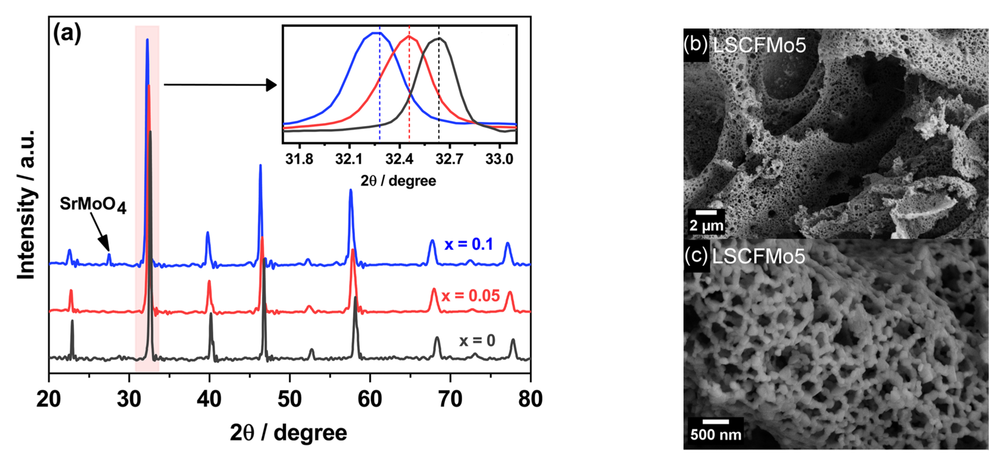
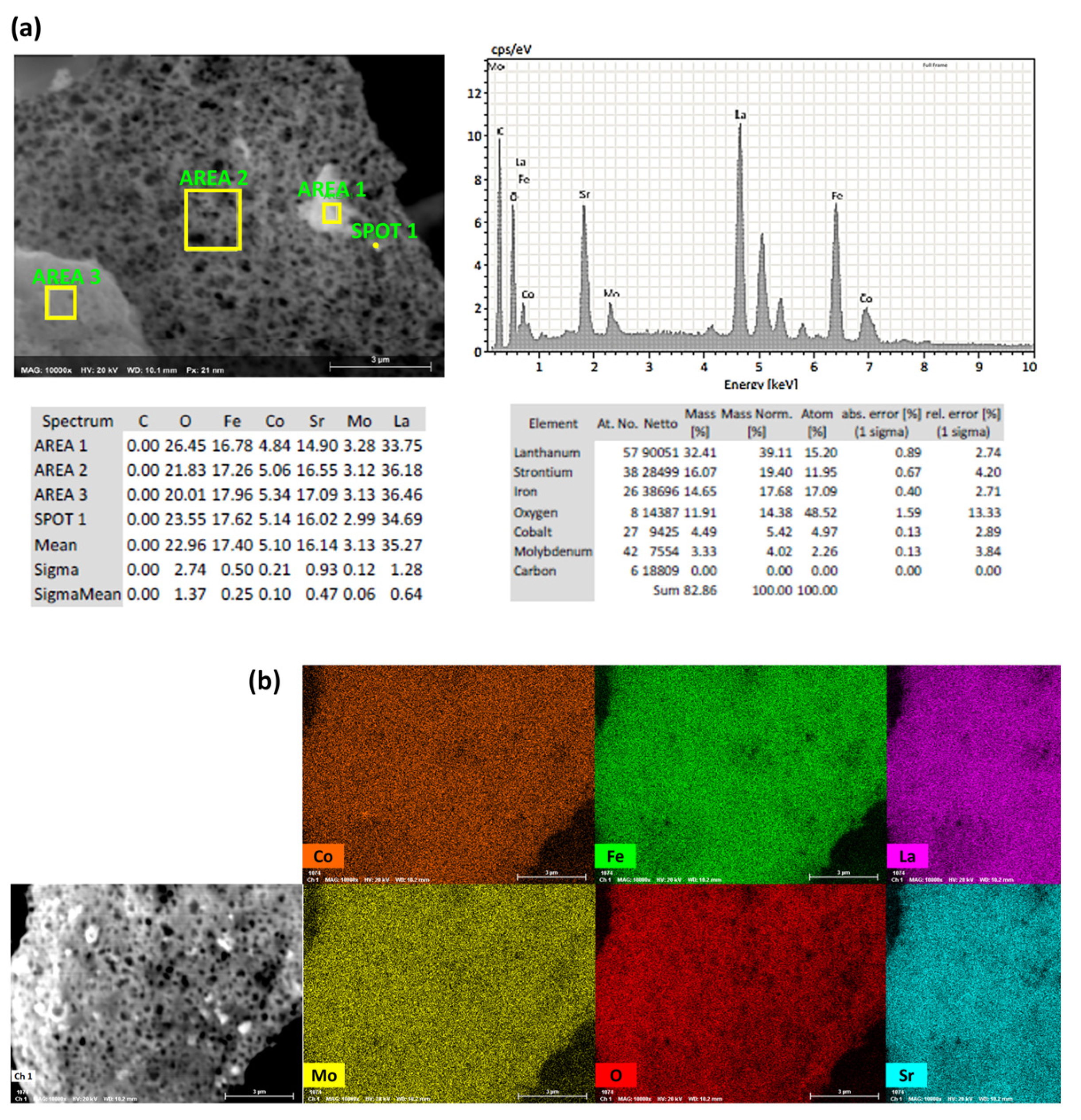
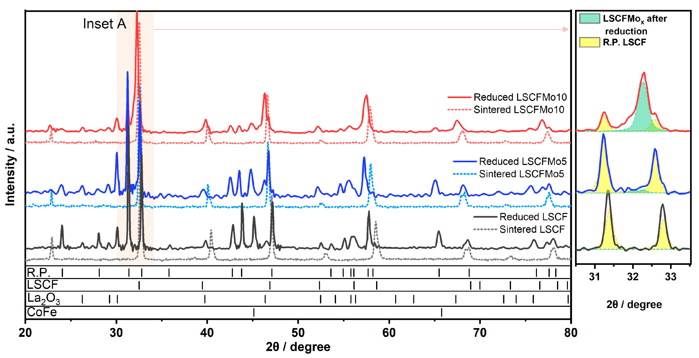
3.1. Powder Characterization
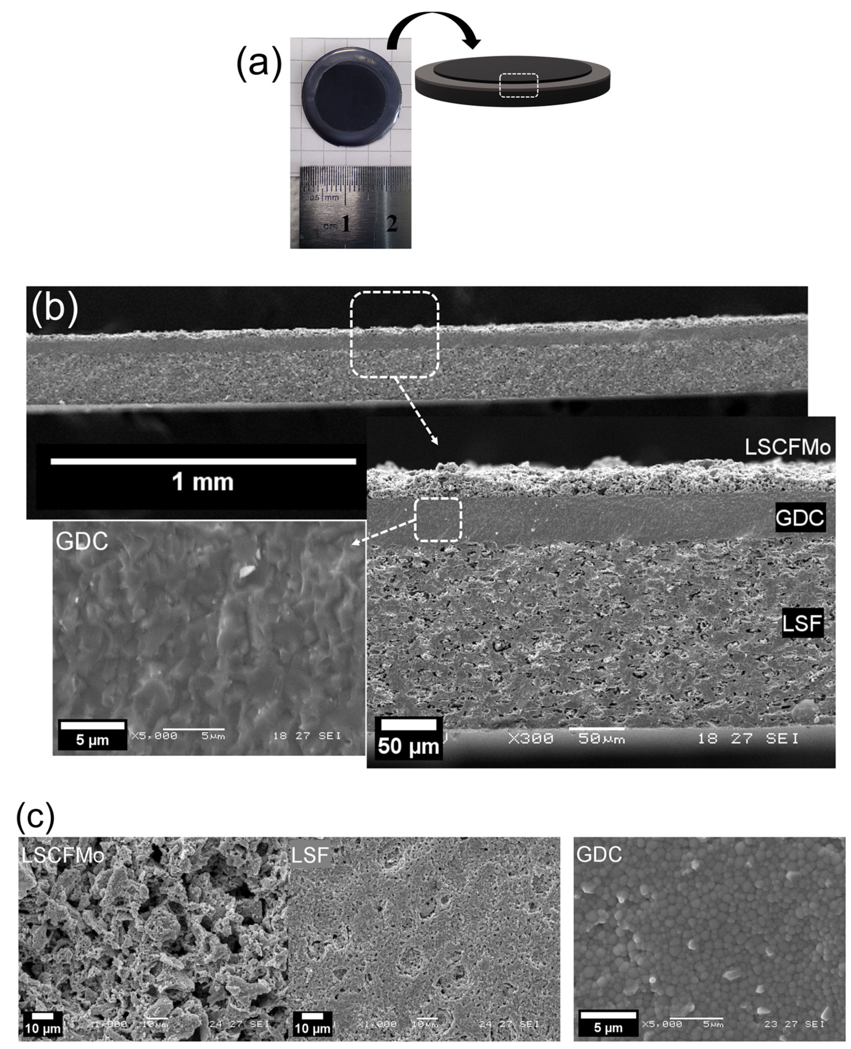
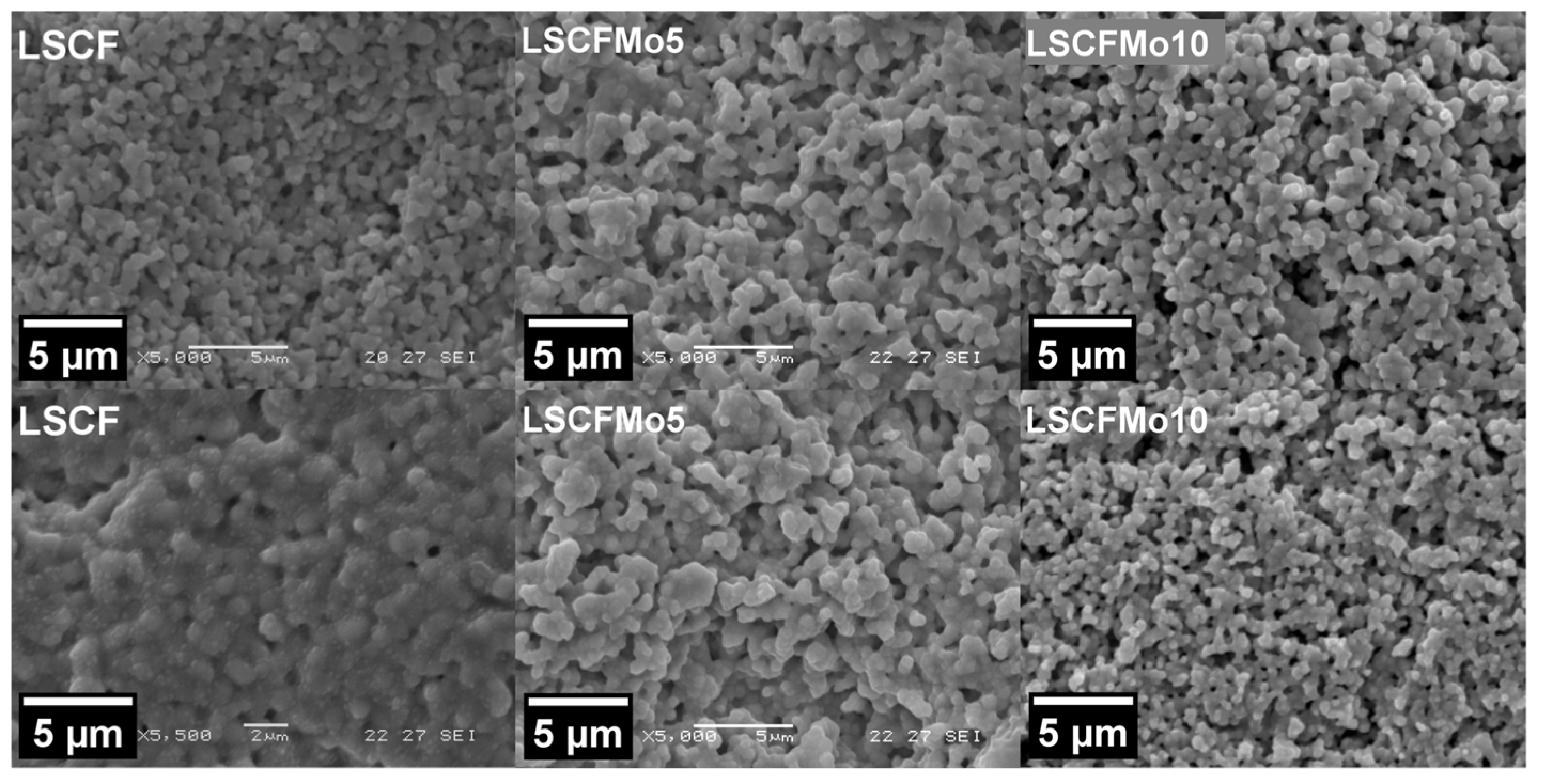
3.2. Cell Design and Microstructure
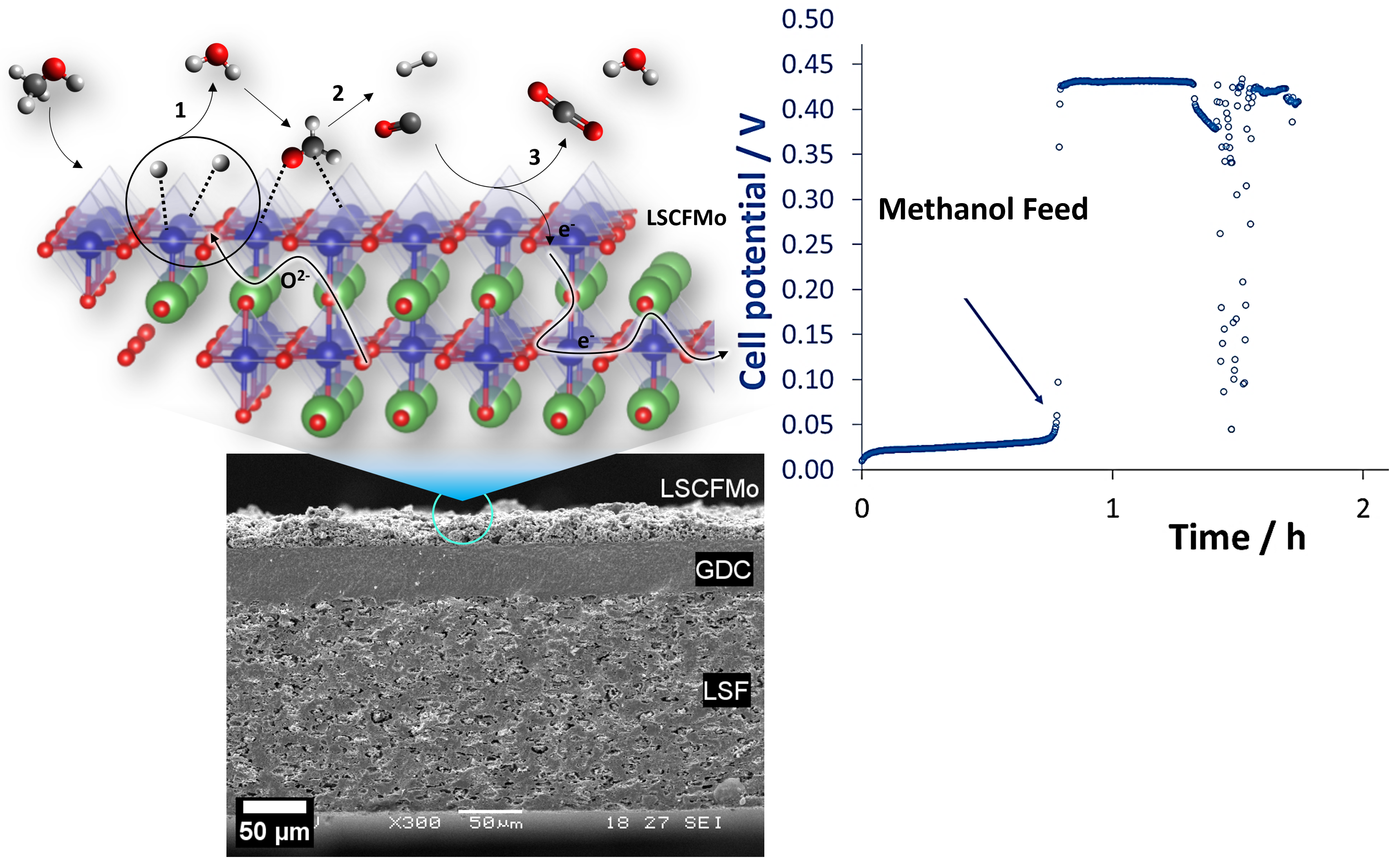
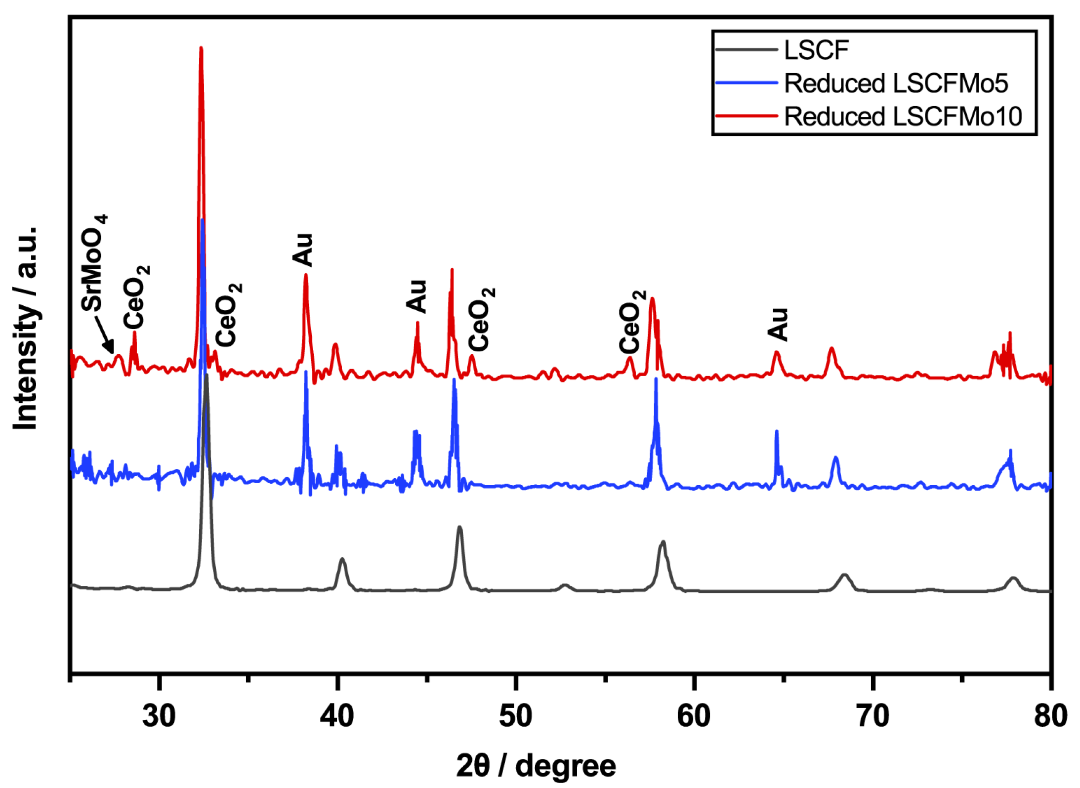
3.3. Anodic Stability
3.4. Electrochemical Measurements
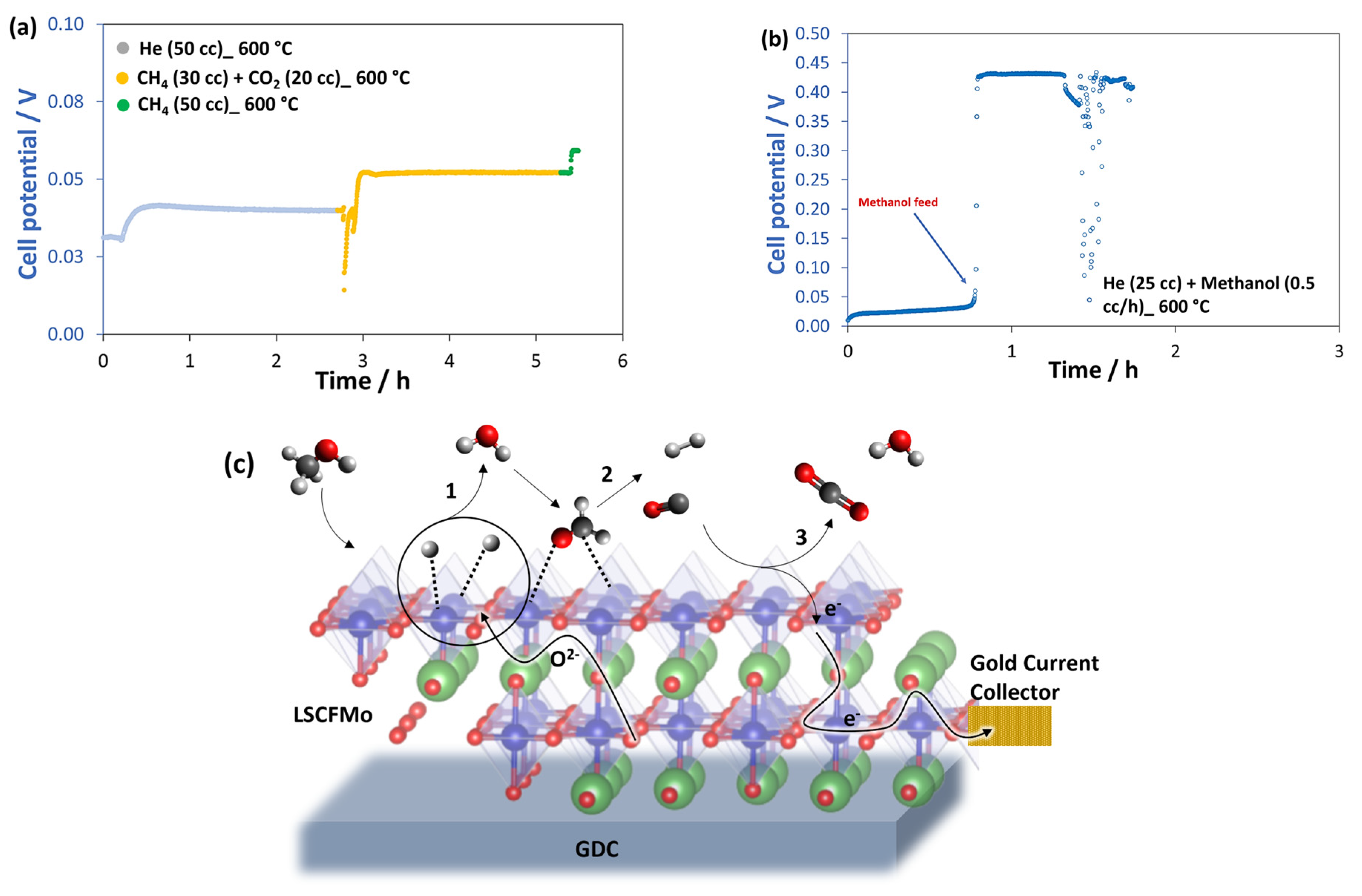
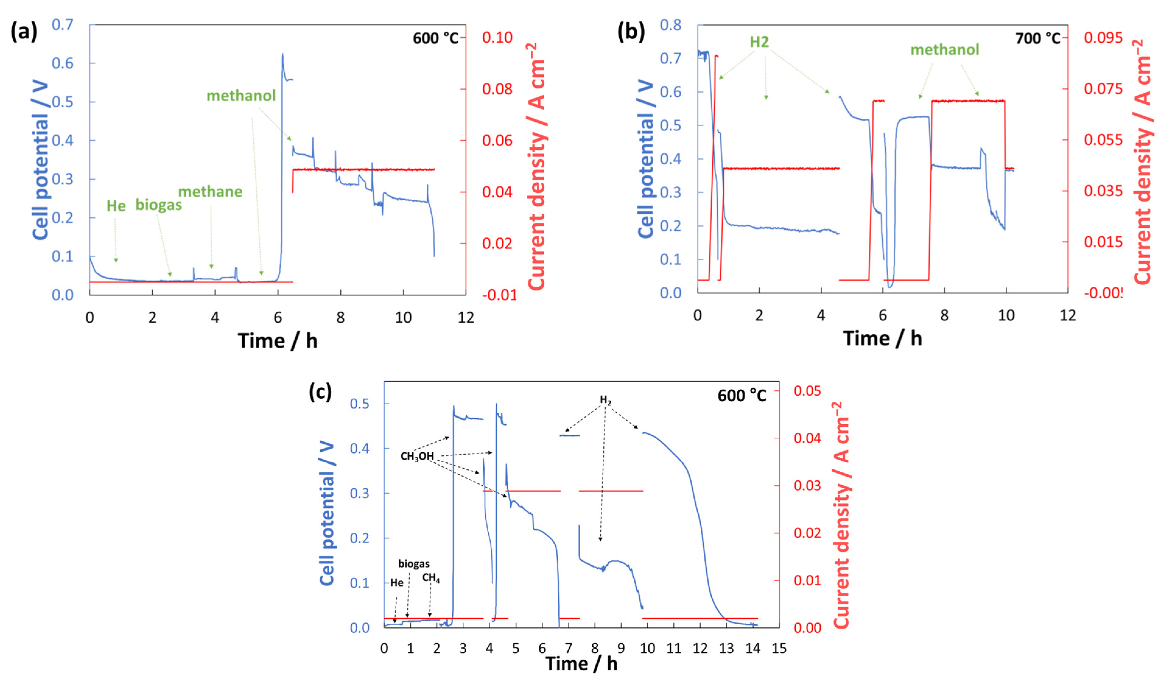
3.4.1. OCV and Durability
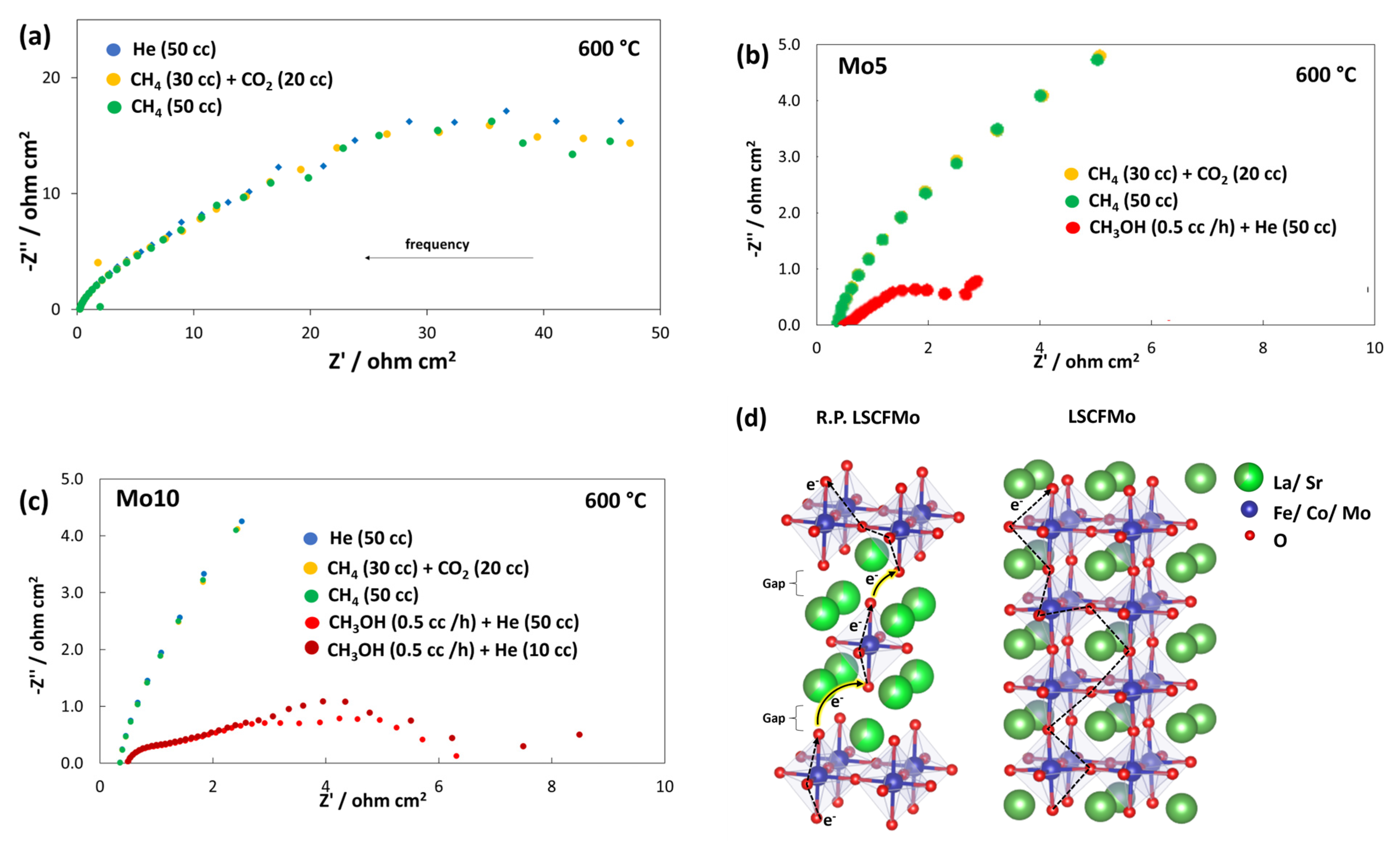
3.4.2. EIS
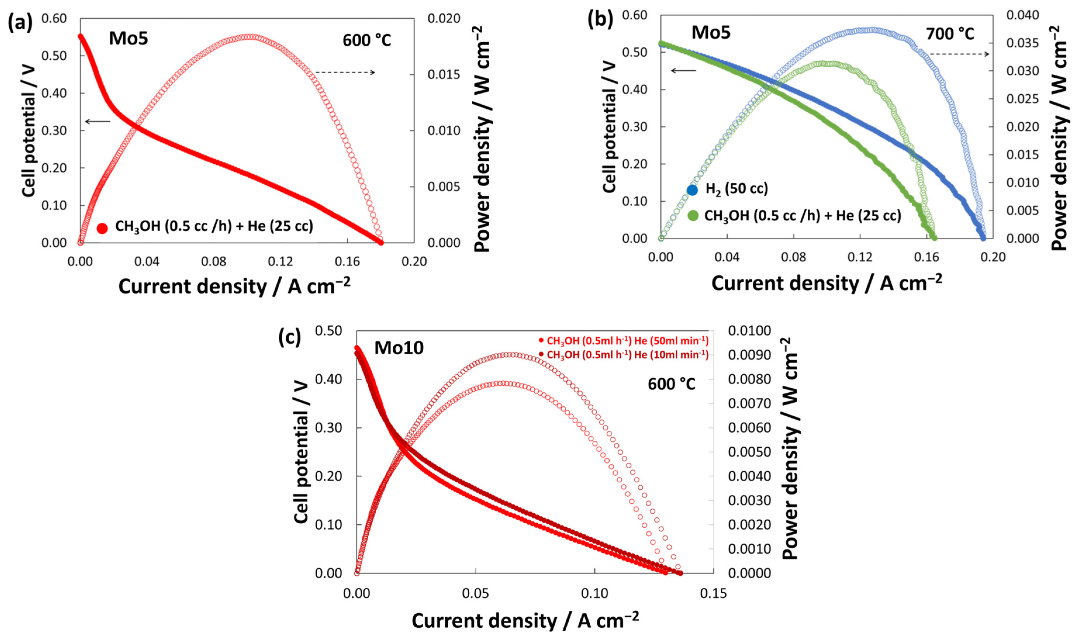
3.4.3. I-V Curves
3.5. Carbon Deposition
4. Conclusions
Author Contributions
Funding
Institutional Review Board Statement
Informed Consent Statement
Data Availability Statement
Conflicts of Interest
References
- Nguyen, V.N.; Fang, Q.; Packbier, U.; Blum, L. Long-term tests of a Jülich planar short stack with reversible solid oxide cells in both fuel cell and electrolysis modes. Int. J. Hydrogen Energy 2013, 38, 4281–4290. [Google Scholar] [CrossRef]
- Saadabadi, S.A.; Thallam Thattai, A.; Fan, L.; Lindeboom, R.E.F.; Spanjers, H.; Aravind, P.V. Solid Oxide Fuel Cells fuelled with biogas: Potential and constraints. Renew. Energy 2019, 134, 194–214. [Google Scholar] [CrossRef]
- Squizzato, E.; Sanna, C.; Glisenti, A.; Costamagna, P. Structural and Catalytic Characterization of La0.6Sr0.4MnO3 Nanofibers for Application in Direct Methane Intermediate Temperature Solid Oxide Fuel Cell Anodes. Energies 2021, 14, 3602. [Google Scholar] [CrossRef]
- Shi, N.; Xie, Y.; Yang, Y.; Xue, S.; Li, X.; Zhu, K.; Huan, D.; Peng, R.; Xia, C.; Lu, Y. Review of anodic reactions in hydrocarbon fueled solid oxide fuel cells and strategies to improve anode performance and stability. Mater. Renew. Sustain. Energy 2020, 9, 6. [Google Scholar] [CrossRef]
- De Marco, V.; Grazioli, A.; Sglavo, V.M. Production of planar copper-based anode supported intermediate temperature solid oxide fuel cells cosintered at 950 °C. J. Power Sources 2016, 328, 235–240. Available online: http://www.sciencedirect.com/science/article/pii/S0378775316310242 (accessed on 16 February 2021). [CrossRef]
- Fang, Z.Z.; Wang, H.; Kumar, V. Coarsening, densification, and grain growth during sintering of nano-sized powders—A perspective. Int. J. Refract. Met. Hard Mater. 2017, 62, 110–117. [Google Scholar] [CrossRef]
- Xie, J.; Hao, W.; Wang, F. Parametric study on interfacial crack propagation in solid oxide fuel cell based on electrode material. Int. J. Hydrogen Energy 2022, 47, 7975–7989. [Google Scholar] [CrossRef]
- Vecino-Mantilla, S.; Squadrito, G.; Torazzi, F.; Sglavo, V.M.; Lo Faro, M. Innovative low-critical raw materials and medium-entropy perovskite for intermediate temperature solid oxide electrochemical cells. Ceram. Int. 2024, 50, 684–691. [Google Scholar] [CrossRef]
- Vinoth Kumar, R.; Khandale, A.P. A review on recent progress and selection of cobalt-based cathode materials for low temperature-solid oxide fuel cells. Renew. Sustain. Energy Rev. 2022, 156, 111985. [Google Scholar] [CrossRef]
- Su, H.; Hu, Y.H. Progress in low-temperature solid oxide fuel cells with hydrocarbon fuels. Chem. Eng. J. 2020, 402, 126235. [Google Scholar] [CrossRef]
- Chen, Y.; Deglee, B.; Tang, Y.; Wang, Z.; Zhao, B.; Wei, Y.; Zhang, L.; Yoo, S.; Pei, K.; Kim, J.H.; et al. A robust fuel cell operated on nearly dry methane at 500 °C enabled by synergistic thermal catalysis and electrocatalysis. Nat. Energy 2018, 3, 1042–1050. [Google Scholar] [CrossRef]
- Tu, H.; Stimming, U. Advances, aging mechanisms and lifetime in solid-oxide fuel cells. J. Power Sources 2004, 127, 284–293. [Google Scholar] [CrossRef]
- Tao, Z.; Fu, M.; Liu, Y. A mini-review of carbon-resistant anode materials for solid oxide fuel cells. Sustain. Energy Fuels 2021, 5, 5420–5430. [Google Scholar] [CrossRef]
- Brunaccini, G.; Lo Faro, M.; La Rosa, D.; Antonucci, V.; Aricò, A.S. Investigation of composite Ni-doped perovskite anode catalyst for electrooxidation of hydrogen in solid oxide fuel cell. Int. J. Hydrogen Energy 2008, 33, 3150–3152. [Google Scholar] [CrossRef]
- Lo Faro, M.; Modafferi, V.; Frontera, P.; Antonucci, P.; Aricò, A.S. Catalytic behavior of Ni-modified perovskite and doped ceria composite catalyst for the conversion of odorized propane to syngas. Fuel Process. Technol. 2013, 113, 28–33. [Google Scholar] [CrossRef]
- Lo Faro, M.; Zignani, S.C.; Aricò, A.S. Lanthanum Ferrites-Based Exsolved Perovskites as Fuel-Flexible Anode for Solid Oxide Fuel Cells. Materials 2020, 13, 3231. [Google Scholar] [CrossRef]
- Vecino-Mantilla, S.; Zignani, S.C.; Vannier, R.N.; Aricò, A.S.; Lo Faro, M. Insights on a Ruddlesden-Popper phase as an active layer for a solid oxide fuel cell fed with dry biogas. Renew. Energy 2022, 192, 784–792. [Google Scholar] [CrossRef]
- Amow, G.; Davidson, I.J.; Skinner, S.J. A comparative study of the Ruddlesden-Popper series, Lan+1NinO3n+1 (n = 1, 2 and 3), for solid-oxide fuel-cell cathode applications. Solid State Ion. 2006, 177, 1205–1210. [Google Scholar] [CrossRef]
- Park, S.; Han, H.; Choi, J.; Lee, S.; Park, M.; Kim, W.B. Ruddlesden–Popper Oxide (La0.6Sr0.4)2(Co,Fe)O4 with Exsolved CoFe Nanoparticles for a Solid Oxide Fuel Cell Anode Catalyst. Energy Technol. 2021, 9, 2100116. [Google Scholar] [CrossRef]
- Chung, Y.S.; Kim, T.; Shin, T.H.; Yoon, H.; Park, S.; Sammes, N.M.; Kim, W.B.; Chung, J.S. In situ preparation of a La1.2Sr0.8Mn0.4Fe0.6O4 Ruddlesden-Popper phase with exsolved Fe nanoparticles as an anode for SOFCs. J. Mater. Chem. A 2017, 5, 6437–6446. [Google Scholar] [CrossRef]
- Yang, X.; Li, R.; Yang, Y.; Wen, G.; Tian, D.; Lu, X.; Ding, Y.; Chen, Y.; Lin, B. Improving stability and electrochemical performance of Ba0.5Sr0.5Co0.2Fe0.8O3−δ electrode for symmetrical solid oxide fuel cells by Mo doping. J Alloys Compd. 2020, 831, 154711. [Google Scholar] [CrossRef]
- Shen, Y.; Song, Y.; Zhao, Y.; Zhao, J.; Yan, M.; Lu, Q.; Bu, Y. Mo-doped Ba0.5Sr0.5Co0.8Fe0.2O3−δ as a high-performance symmetric electrode for solid oxide fuel cells. J Alloys Compd. 2022, 928, 167029. [Google Scholar] [CrossRef]
- Bian, L.; Liu, C.; Li, S.; Peng, J.; Li, X.; Guan, L.; Liu, U.; Peng, J.H.; An, S.; Song, X. Highly stable La0.5Sr0.5Fe0.9Mo0.1O3−δ electrode for reversible symmetric solid oxide cells. Int. J. Hydrogen Energy 2020, 45, 19813–19822. [Google Scholar] [CrossRef]
- Li, J.; Lv, T.; Hou, N.; Li, P.; Yao, X.; Fan, L.; Gan, T.; Zhao, Y.; Li, Y. Molybdenum substitution at the B-site of lanthanum strontium titanate anodes for solid oxide fuel cells. Int. J. Hydrogen Energy 2017, 42, 22294–22301. [Google Scholar] [CrossRef]
- Wang, S.; Jiang, H.; Gu, Y.; Yin, B.; Chen, S.; Shen, M.; Zheng, Y.; Ge, L.; Chen, H.; Guo, L. Mo-doped La0.6Sr0.4FeO3−δ as an efficient fuel electrode for direct electrolysis of CO2 in solid oxide electrolysis cells. Electrochim. Acta 2020, 337, 135794. Available online: http://www.sciencedirect.com/science/article/pii/S0013468620301869 (accessed on 16 February 2021). [CrossRef]
- Liu, Y.; Zhou, F.; Chen, X.; Wang, C.; Zhong, S. Enhanced electrochemical activity and stability of LSCF cathodes by Mo doping for intermediate temperature solid oxide fuel cells. J. Appl. Electrochem. 2021, 51, 425–433. Available online: https://link.springer.com/article/10.1007/s10800-020-01515-z (accessed on 21 December 2021). [CrossRef]
- He, B.; Wang, Z.; Zhao, L.; Pan, X.; Wu, X.; Xia, C. Ti-doped molybdenum-based perovskites as anodes for solid oxide fuel cells. J. Power Sources 2013, 241, 627–633. Available online: http://www.sciencedirect.com/science/article/pii/S0378775313007684 (accessed on 16 February 2021). [CrossRef]
- Li, H.; Tian, Y.; Wang, Z.; Qie, F.; Li, Y. An all perovskite direct methanol solid oxide fuel cell with high resistance to carbon formation at the anode. RSC Adv. 2012, 2, 3857–3863. [Google Scholar] [CrossRef]
- Aguadero, A.; Pérez-Coll, D.; Alonso, J.A.; Skinner, S.J.; Kilner, J. A New Family of Mo-Doped SrCoO3−δ Perovskites for Application in Reversible Solid State Electrochemical Cells. Chem. Mater. 2012, 24, 2655–2663. [Google Scholar] [CrossRef]
- Lu, X.; Yang, Y.; Ding, Y.; Chen, Y.; Gu, Q.; Tian, D.; Yu, W.; Lin, B. Mo-doped Pr0.6Sr0.4Fe0.8Ni0.2O3−δ as potential electrodes for intermediate-temperature symmetrical solid oxide fuel cells. Electrochim. Acta 2017, 227, 33–40. Available online: http://www.sciencedirect.com/science/article/pii/S0013468616327293 (accessed on 16 February 2021). [CrossRef]
- Somalu, M.R.; Muchtar, A.; Daud, W.R.W.; Brandon, N.P. Screen-printing inks for the fabrication of solid oxide fuel cell films: A review. Renew. Sustain. Energy Rev. 2017, 75, 426–439. [Google Scholar] [CrossRef]
- Da Conceição, L.; Silva, A.M.; Ribeiro, N.F.P.; Souza, M.M.V.M. Combustion synthesis of L0.7Sr0.3Co0.5Fe0.5O3 (LSCF) porous materials for application as cathode in IT-SOFC. Mater. Res. Bull. 2011, 46, 308–314. [Google Scholar] [CrossRef]
- Deganello, F.; Tyagi, A.K. Solution combustion synthesis, energy and environment: Best parameters for better materials. Prog. Cryst. Growth Charact. Mater. 2018, 64, 23–61. [Google Scholar] [CrossRef]
- Li, S.; Bergman, B.; Zhao, Z. Synthesis and characterization of lanthanum aluminate powders via a polymer complexing plus combustion route. Mater. Chem. Phys. 2012, 132, 309–315. [Google Scholar] [CrossRef]
- Deganello, F. Nanomaterials for environmental and energy applications prepared by solution combustion based-methodologies: Role of the fuel. Mater. Today Proc. 2017, 4, 5507–5516. [Google Scholar] [CrossRef]
- Zhang, P.; Guan, G.; Khaerudini, D.S.; Hao, X.; Xue, C.; Han, M.; Kasai, Y.; Abudula, A. B-site Mo-doped perovskite Pr0.4Sr0.6 (Co0.2Fe0.8)1−xMoxO3−σ (x = 0, 0.05, 0.1 and 0.2) as electrode for symmetrical solid oxide fuel cell. J. Power Sources 2015, 276, 347–356. Available online: http://www.sciencedirect.com/science/article/pii/S0378775314020084 (accessed on 16 February 2021). [CrossRef]
- Neacsa, D.M.; Abbassi, K.; Guesmi, H.; Coddet, P.L.; Vulliet, J.; El Amrani, M.; Dealmeida-Didry, S.; Roger, S.; Ta Phuoc, V.; Sopracase, R.; et al. Nb and Cu co-doped (La,Sr)(Co,Fe)O3: A stable electrode for solid oxide cells. RSC Adv. 2021, 11, 10479–10488. Available online: https://pubs.rsc.org/en/content/articlehtml/2021/ra/d0ra10313f (accessed on 26 January 2022). [CrossRef]
- Goodenough, J.B.; Huang, Y.H. Alternative anode materials for solid oxide fuel cells. J Power Sources 2007, 173, 1–10. [Google Scholar] [CrossRef]
- Lo Faro, M.; Reis, R.M.; Saglietti, G.G.A.; Oliveira, V.L.; Zignani, S.C.; Trocino, S.; Maisano, S.; Ticianelli, E.; Hodnik, N.; Ruiz-Zepeda, F.; et al. Solid oxide fuel cells fed with dry ethanol: The effect of a perovskite protective anodic layer containing dispersed Ni-alloy @ FeOx core-shell nanoparticles. Appl. Catal. B Environ. 2018, 220, 98–110. [Google Scholar] [CrossRef]
- Hou, Y.; Wang, L.; Bian, L.; Chen, N.; Chou, K. High performance of Mo-doped La0.6Sr0.4Fe0.9Ni0.1O3−δ perovskites as anode for solid oxide fuel cells. Electrochim. Acta 2018, 292, 540–545. Available online: http://www.sciencedirect.com/science/article/pii/S001346861832200X (accessed on 16 February 2021). [CrossRef]
- Yang, B.C.; Koo, J.; Shin, J.W.; Go, D.; Shim, J.H.; An, J. Direct Alcohol-Fueled Low-Temperature Solid Oxide Fuel Cells: A Review. Energy Technol. 2019, 7, 5–19. [Google Scholar] [CrossRef]
- Cimenti, M.; Buccheri, M.A.; Hill, J.M. Direct Utilization of Methanol and Ethanol on La0.75Sr0.25Cr0.5Mn0.5O3−δ Anodes for Solid Oxide Fuel Cells. Electrocatalysis 2012, 3, 59–67. [Google Scholar] [CrossRef]
- Zainon, A.N.; Somalu, M.R.; Kamarul Bahrain, A.M.; Muchtar, A.; Baharuddin, N.A.; Muhammed, M.A.; Osman, N.; Samat, A.A.; Azad, A.K.; Brandon, N.P. Challenges in using perovskite-based anode materials for solid oxide fuel cells with various fuels: A review. Int. J. Hydrogen Energy 2023, 48, 20441–20464. [Google Scholar] [CrossRef]
- Han, D.; Liu, Y.; Wang, S.; Zhan, Z. Electrochimica Acta temperature solid oxide fuel cell cathodes. Electrochim. Acta 2014, 143, 168–174. [Google Scholar] [CrossRef]
- Flores, J.J.A.; Rodríguez, M.M.Á.; Espinosa, G.A.; Vera, J.V.A. Advances in the development of titanates for anodes in SOFC. Int. J. Hydrogen Energy 2018, 44, 12529–12542. [Google Scholar] [CrossRef]


Disclaimer/Publisher’s Note: The statements, opinions and data contained in all publications are solely those of the individual author(s) and contributor(s) and not of MDPI and/or the editor(s). MDPI and/or the editor(s) disclaim responsibility for any injury to people or property resulting from any ideas, methods, instructions or products referred to in the content. |
© 2024 by the authors. Licensee MDPI, Basel, Switzerland. This article is an open access article distributed under the terms and conditions of the Creative Commons Attribution (CC BY) license (https://creativecommons.org/licenses/by/4.0/).
Share and Cite
Javan, K.Y.; Lo Faro, M.; Vecino-Mantilla, S.; Sglavo, V.M. Mo-Doped LSCF as a Novel Coke-Resistant Anode for Biofuel-Fed SOFC. Materials 2024, 17, 869. https://doi.org/10.3390/ma17040869
Javan KY, Lo Faro M, Vecino-Mantilla S, Sglavo VM. Mo-Doped LSCF as a Novel Coke-Resistant Anode for Biofuel-Fed SOFC. Materials. 2024; 17(4):869. https://doi.org/10.3390/ma17040869
Chicago/Turabian StyleJavan, Kimia Y., Massimiliano Lo Faro, Sebastian Vecino-Mantilla, and Vincenzo M. Sglavo. 2024. "Mo-Doped LSCF as a Novel Coke-Resistant Anode for Biofuel-Fed SOFC" Materials 17, no. 4: 869. https://doi.org/10.3390/ma17040869