
Review: Inelastic Constitutive Modeling: Polycrystalline Materials †

Abstract
:
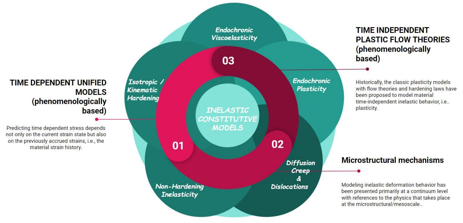
1. Introduction
2. Early Efforts in Modeling Creep Behavior
3. Creep Strain Models Based on Microstructural Mechanisms
4. Irradiation-Induced Creep
5. Time-Independent Models Based on Continuum Principles: Plasticity
6. Time-Dependent Isotropic Unified Models: Viscoplasticity
7. Unified Viscoplasticity Models Based on Potential Functions
7.1. Robinson’s Model
= F (J2)
7.2. Chaboche’s Model
8. Viscoplastic Constitutive Models Not Based on Potential Functions
8.1. Bodner’s Model
8.2. Walker’s Model
8.3. Miller’s Model
8.4. Krieg, Swearengen, and Rhode’s Model
8.5. Hart’s Model
9. Integral-Based Viscoplastic Models
Valanis Model
10. Design Scale
11. The Bridge from Microstructure to Continuum: Time-Dependent Behavior
12. Concluding Remarks
Funding
Institutional Review Board Statement
Informed Consent Statement
Data Availability Statement
Conflicts of Interest
References
- Andrade, E.N.D.C. On the Viscous Flow in Metals, and Allied Phenomena. Proc. R. Soc. Sect. A–Math. Phys. Sci. 1910, 84, 1–12. [Google Scholar]
- Andrade, E.N.D.C. The Flow in Metals under Large Constant Stresses. Proc. R. Soc. Sect. A–Math. Phys. Sci. 1914, 90, 329–342. [Google Scholar]
- Norton, F.H. The Creep of Steel at High Temperatures; McGraw-Hill: London, UK, 1929. [Google Scholar]
- Bailey, R.W. Creep of Steel Under Simple and Compound Stress. Engineering 1930, 121, 129–265. [Google Scholar]
- Odqvist, F.K.G. International Congress of Applied Mechanics, Cambridge, Proceedings; Cambridge University Press: Cambridge, UK, 1935; pp. 228–229. [Google Scholar]
- Odqvist, F.K.G. Historical Survey of the Development of Creep Mechanics from its Beginnings in the Last Century to 1970. In Creep in Structures, IUTAM, 3rd Symposium; Springer: Leicester, UK, 1980; pp. 1–12. [Google Scholar]
- Schapery, R.A. Nonlinear Viscoelastic and Viscoplastic Constitutive Equations Based on Thermodynamics. Mech. Time-Depend. Mater. 1997, 1, 209–240. [Google Scholar] [CrossRef]
- Findley, W.N.; Lai, J.S.; Onaran, K. Creep and Relaxation of Nonlinear Viscoelastic Materials; Dover Publications Inc.: New York, NY, USA, 1976; ISBN 978-0486660165. [Google Scholar]
- Besseling, J.F. Theory of elastic, plastic, and creep deformations of an initially isotropic material showing anisotropic strain-hardening, creep recovery, and secondary creep. J. Appl. Mech. 1958, 25, 529. [Google Scholar] [CrossRef]
- Onimus, F.; Jourdan, T.; Xu, C.; Campbell, A.A.; Griffiths, M. Irradiation Creep in Materials. In Comprehensive Nuclear Materials, 2nd ed.; Elsevier: Amsterdam, The Netherlands, 2021; pp. 301–366. [Google Scholar]
- Jaske, C.E.; Leis, B.N.; Pugh, C.E. Monotonic and Cyclic Stress-Strain Response of Annealed 21/4Cr-1Mo Steel. In Symposium on Structural Materials for Service at Elevated Temperatures in Nuclear Power Generation; Schaefer, A.O., Ed.; ASME Winter Annual Meeting: New York, NY, USA, 1975. [Google Scholar]
- Pugh, C.E.; Robinson, D.N. Some Trends in Constitutive Equation Model Development for High-Temperature Behavior of Fast-Reactor Structural Alloys. Nucl. Eng. Des. 1978, 48, 269. [Google Scholar] [CrossRef]
- Robinson, D.N. ORNL TM-5110; Candidate Creep-Recovery Model for 2 1/4 Cr-1 Mo Steel and Its Experimental Implementation. Energy Research and Development Administration: Oak Ridge, TN, USA, 1975.
- Robinson, D.N. ORNL-5136; Developments Toward Refined Constitutive Laws for Reactor System Metals. Energy Research and Development Administration: Oak Ridge, TN, USA, 1975; pp. 15–23.
- Robinson, D.N. ORNL TM-5571; On the Concept of a Flow Potential and the Stress-Strain Relations of Reactor System Metals. Energy Research and Development Administration: Oak Ridge, TN, USA, 1976.
- Robinson, D.N. ORNL TM-5235; Tests for Examining the Concept of a Flow Potential in the Stress-Strain Relations of Reactor System Metals. Energy Research and Development Administration: Oak Ridge, TN, USA, 1976.
- Robinson, D.N. ORNL TM-5339; Developments toward Refined Constitutive Laws. Energy Research and Development Administration: Oak Ridge, TN, USA, 1977.
- Robinson, D.N. ORNL TM-5969; A Unified Creep-Plasticity Model for Structural Metals at High Temperature. Energy Research and Development Administration: Oak Ridge, TN, USA, 1978.
- Robinson, D.N.; Swindeman, R.W. ORNL TM-8444; Unified Creep-plasticity Constitutive Equations for 2-1/4 Cr-1Mo Steel at Elevated Temperature. Energy Research and Development Administration: Oak Ridge, TN, USA, 1982.
- Robinson, D. N Constitutive Relationships for Anisotropic High Temperature Alloys. Nucl. Eng. Des. 1984, 83, 389–396. [Google Scholar] [CrossRef]
- Robinson, D.N.; Bartolotta, P.A. NASA CR-174836; Viscoplastic Constitutive Relationships with Dependence on Thermomechanical History. Energy Research and Development Administration: Oak Ridge, TN, USA, 1985.
- Chaboche, J.L. Bulletin de L’Academie des Sciences. Série Des Sci. Tech. 1977, 1, 33. [Google Scholar]
- Chaboche, J.L. A Review of Some Plasticity and Viscoplasticity Constitutive Theories. Int. J. Plast. 2008, 1, 33. [Google Scholar] [CrossRef]
- Chaboche, J.L.; Nouailhas, D. On Various Nonlinear Kinematic Hardening Rules in Cyclic Plasticity and Viscoplasticity. In Proceedings of the Computational Mechanics ’88: Theory and Applications: Proceedings of the International Conference on Computational Engineering Science, Atlanta, GA, USA, 10–14 April 1988; pp. 19.i.1–19.i.4. [Google Scholar]
- Bodner, S.R. Constitutive Equations for Dynamic Material Behavior. In Mechanical Behavior of Materials Under Dynamic Loading; U.S. Lindholm, Ed.; Springer: New York, NY, USA, 1968; pp. 176–190. [Google Scholar]
- Bodner, S.R.; Partom, Y. A Large Deformation Elastic-Viscoplastic Analysis of a Thick-Walled Spherical Shell. ASME J. Appl. Mech. 1972, 39, 751–757. [Google Scholar] [CrossRef]
- Bodner, S.R.; Partom, Y. Constitutive Equations for Elastic-Viscoplastic Strain Hardening Materials. ASME J. Appl. Mech. 1978, 42, 385–389. [Google Scholar] [CrossRef]
- Bodner, S.R.; Partom, I.; Partom, Y. Uniaxial Cyclic Loading of Elastic-viscoplastic Materials. ASME J. Appl. Mech. 1979, 46, 805–810. [Google Scholar] [CrossRef]
- Bodner, S.R. A Procedure for Including Damage in Constitutive Equations for Elastic- viscoplastic Work-hardening Materials. In Proceedings of the IUTAM Symposium on Physical Nonlinearities in Structural Analysis, Senlis, France, 27–30 May 1981; pp. 21–28. [Google Scholar]
- Stouffer, D.C.; Bodner, S.R. A Relationship Between Theory and Experiment for a State Variable Constitutive Equation. In Mechanical Testing for Deformation Model Development; ASTM STP: West Conshohocken, PN, USA, 1982; Volume 765, pp. 239–250. [Google Scholar]
- Bodner, S.R. Evolution Equations for Anisotropic Hardening and Damage of Elastic-Viscoplastic Materials. In Proceedings of the Conference on Plasticity Today, Udine, Italy, 13 July 1983. [Google Scholar]
- Bodner, S.R.; Stouffer, D.C. Comments on Anisotropic Plastic Flow and Incompressibility. Int. J. Eng. Sci. 1983, 21, 211–215. [Google Scholar] [CrossRef]
- Lindholm, U.S.; Chan, K.S.; Bodner, S.R.; Weber, R.M.; Walker, K.P.; Cassenti, B.N. Constitutive Modeling for Isotropic Materials (HOST). In First Annual Contract Report NASA CR-174718; NASA: Washington, DC, USA, 1984. [Google Scholar]
- Lindholm, U.S.; Chan, K.S.; Bodner, S.R.; Weber, R.M.; Walker, K.P.; Cassenti, B.N. Constitutive Modelling for Isotropic Materials (HOST). In 2nd Annual Contract Report, NASA CR-174980; NASA: Washington, DC, USA, 1985. [Google Scholar]
- Chan, K.S.; Bodner, S.R.; Lindholm, U.S. Phenomenological Modeling of Hardening and Thermal Recovery in Metals. J. Eng. Mater. Technol. Am. Soc. Mech. Eng. 1988, 110, 1–8. [Google Scholar] [CrossRef]
- Miller, A.K. An Inelastic Constitutive Model for Monotonic, Cyclic and Creep Deformation: Part 1–Equation Development and Analytical Procedures. J. Eng. Mater. Technol. 1976, 99, 97–105. [Google Scholar] [CrossRef]
- Miller, A.K. Modelling of Cyclic Plasticity: Improvements in Simulating Normal and Anomalous Bauschinger Effects. J. Eng. Mater. Technol. 1980, 102, 215–220. [Google Scholar] [CrossRef]
- Schmidt, C.G.; Miller, A.K. A Unified Phenomenological Model for Non-elastic Deformation of Type 316 Stainless Steel-Part I: Development of the Model and Calculation of the Material Constants. Res. Mech. 1981, 3, 109–129. [Google Scholar]
- Schmidt, C.G.; Miller, A.K. A Unified Phenomenological Model for Non-elastic Deformation of Type 316 Stainless Steel-Part II: Fitting and Predictive Capabilities. Res. Mech. 1981, 3, 175–193. [Google Scholar]
- Ruano, O.A.; Miller, A.K.; Sherby, O.D. The Influence of Pipe Diffusion on the Creep of Fine-grained Materials. Mater. Sci. Eng. 1981, 51, 9–16. [Google Scholar] [CrossRef]
- Kassner, M.E.; Rubin, K.A.; Miller, A.K. Verification of a Microstructurally based Equation for Elevated-temperature Transient Isotropic Hardening. In Strength of Metals and Alloys; Pergamon Press: Oxford, UK, 1982; Volume 2, pp. 581–587. [Google Scholar]
- Miller, A.K.; Ziaai-Moayyed, A.A. Some Critical Experimental Tests of the MATMOD Constitutive Equations with Respect to Directional Hardening and Cyclic Deformation. In Mechanical Testing for Deformation Model Development, STP 765; ASTM: West Conshohocken, PN, USA, 1982; pp. 202–222. [Google Scholar]
- Miller, A.K.; Kassner; Sherby, O.D. The Separate Roles of Subgrains and Forest Dislocations in the Isotropic Hardening of Type 304 Stainless Steel. Met. Trans. 1982, A, 13A. [Google Scholar]
- Schmidt, C.G.; Miller, A.K. The Effect of Solutes on the Strength and Strain Hardening Behavior of Alloys. Acta Met. 1982, 30, 615–625. [Google Scholar] [CrossRef]
- Lowe, T.C.; Miller, A.K. Improved Constitutive Equations for Modelling Strain Softening-Part 1: Conceptual Development and Part 2: Predictions for Aluminum. J. Eng. Mater. Technol. 1984, 106, 337–348. [Google Scholar] [CrossRef]
- Hedling, D.E.; Miller, A.K. The Incorporation of Yield Surface Distortion into a Unified Constitutive Model, Part I: Equation Development. Acta Mech. 1987, 69, 9–23. [Google Scholar] [CrossRef]
- Miller, A.K. Unified Constitutive Equations for Creep and Plasticity; Elsevier: London, UK, 1987. [Google Scholar]
- Miller, A.K.; Obalueki, A.O.; Lee, C.W.; Tanaka, T.G.; Lee, S.B. A Unified Model for Fatigue Crack Initiation and Growth, with Emphasis on Short-Crack Behavior, Crack Closure Effects Variable–Temperature Fatigue and Creep-Fatigue Interaction. Mat. Sci. Eng. 1988, A103, 71–93. [Google Scholar] [CrossRef]
- Walker, K.P. Representation of Hastelloy-X Behavior at Elevated Temperature with a Functional Theory of Viscoplasticity. In Proceedings of the ASME Pressure Vessels Conference, San Francisco, CA, USA, 12–15 August 1980. [Google Scholar]
- Walker, K.P. NASA CR-165533; Research and Development Program for Non-linear Structural Modelling with Advanced Time-temperature Dependent Constitutive Relationships. NASA: Washington, DC, USA, 1981.
- Freed, A.D.; Walker, K.P. NASA TM 102338; Refinements in a Viscoplastic Model. NASA: Washington, DC, USA, 1989.
- Chan, K.S.; Lindholm, U.S.; Bodner, S.R.; Walker, K.P. High Temperature Deformation Under Uniaxial Loading: Theory and Experiment. J. Eng. Mater. Technol. ASME 1989, 111, 345–353. [Google Scholar] [CrossRef]
- Allen, D.H.; Harris, C.E. NASA TM 102727; A Review of Models for Nonlinear Constitutive Models for Metals. NASA: Washington, DC, USA, 1990.
- Chamis, C.C. NASA TM 83320; Simplified Composite Micromechanics Equations for Hygral, Thermal and Mechanical Properties. NASA: Washington, DC, USA, 1983.
- Coble, R.L. A Model for Boundary Diffusion Controlled Creep in Polycrystalline Materials. J. Appl. Phys. 1963, 34, 1679–1682. [Google Scholar] [CrossRef]
- Nabarro, F.R.N. Report of Conference on Strength of Solids. Phys. Soc. 1948, 2, 75–90. [Google Scholar]
- Herring, C. Diffusional Viscosity of a Polycrystalline Solid. J. Appl. Phys. 1950, 21, 437. [Google Scholar] [CrossRef]
- Weertman, J.R. Theory of steady-state creep based on dislocation climb. J. Appl. Phys. 1955, 26, 1213–1217. [Google Scholar] [CrossRef]
- Ponter, A.R.S.; Leckie, F.A. Constitutive Relationships for the Time Dependent Deformation of Metals. ASME J. Eng. Mater. Technol. 1976, 98, 47–51. [Google Scholar] [CrossRef]
- Rice, J.R. On the Structure of Stress-Strain Relations for Time Dependent Plastic Deformation in Metals. J. Appl. Mech. 1970, 37, 728–737. [Google Scholar] [CrossRef]
- Was, G.S. Fundamentals of Radiation Materials Science-Metals and Alloys, 2nd ed.; Springer: New York, NY, USA, 2017. [Google Scholar]
- Onimus, F.; Jourdan, T.; Xu, C.; Campbell, A.A.; Griffiths, M. Chapter 1.10: Irradiation Creep in Materials. In Comprehensive Nuclear Materials, 2nd ed.; Konings, R.J.M., Stoller, R.E., Eds.; Elsevier: Oxford, UK, 2020; pp. 310–366. [Google Scholar]
- Roberts, A.C.; Cottrell, A.H. LXXII. Creep of Alpha Uranium During Irradiation with Neutrons. A J. Theor. Exp. Appl. Phys. 1956, 1, 711–717. [Google Scholar] [CrossRef]
- Hesketh, R.V. A Possible Mechanism of Irradiation Creep and Its Reference to Uranium. Philos. Mag. A J. Theor. Exp. Appl. Phys. 1962, 7, 1417–1420. [Google Scholar] [CrossRef]
- Koyanagi, T.; Katoh, Y.; Ozawa, K.; Shimoda, K.; Hinoki, T.; Snead, L.L. Neutron-Irradiation Creep of Silicon Carbide Materials Beyond the Initial Transient. J. Nucl. Mater. 2016, 478, 97–111. [Google Scholar] [CrossRef]
- Campbell, A.A. Historical Experiment to Measure Irradiation-Induced Creep of Graphite. Carbon 2018, 139, 279–288. [Google Scholar] [CrossRef]
- Hesketh, R.V. The Mechanisms of Irradiation Creep in Graphite. Philos. Mag. 1965, 11, 917–927. [Google Scholar] [CrossRef]
- Kelly, B.T.; Brocklehurst, J.E. ORNL/NPR-92-58; Analysis of Irradiation Creep in Reactor Graphite. Energy Research and Development Administration: Oak Ridge, TN, USA, 1993.
- Kelly, B.T.; Brocklehurst, J.E. UKAEA Reactor Group Studies of Irradiation-Induced Creep in Graphite. J. Nucl. Mater. 1977, 65, 79–85. [Google Scholar] [CrossRef]
- Kelly, B.T.; Foreman, A.J.E. The Theory of Irradiation Creep in Reactor Graphite–The Dislocation Pinning-Unpinning Model. Carbon 1974, 12, 151–158. [Google Scholar] [CrossRef]
- Campbell, A.A.; Was, G.S. Proton Irradiation-Induced Creep of Ultra-Fine Grain Graphite. Carbon 2014, 77, 993–1010. [Google Scholar] [CrossRef]
- Sarkar, A.; Eapen, J.; Raj, A.; Murty, K.L.; Burchell, T.D. Modeling Irradiation Creep of Graphite Using Rate Theory. J. Nucl. Mater. 2016, 473, 197–205. [Google Scholar] [CrossRef]
- Heggie, M.I.; Suarez-Martinez, I.; Davidson, C.; Haffenden, G. Buckle, Ruck and Tuck: A Proposed New Model for the Response of Graphite to Neutron Irradiation. J. Nucl. Mater. 2011, 413, 150–155. [Google Scholar] [CrossRef]
- Coulomb, C.A. Essai sur une application des regles des maximis et minimis a quelquels problemesde statique relatifs, a la architecture. Mem. Acad. Roy. Div. Sav. 1776, 7, 343–387. [Google Scholar]
- Tresca, H.E. Mémoire sur l’écoulement des corps solides soumis à de fortes pressions. Comptes Rendus De L’academie Des Sci. 1864, 59, 754–759. [Google Scholar]
- Von Mises, R. Mechanik der festen Körper im plastisch deformablen Zustand. Nachrichten von der Gesellschaft der Wissenschaften zu Göttingen. Math.-Phys. Kl. 1913, 582–592. [Google Scholar]
- Hencky, H. Zur Theorie plasticher Deformationen und der hierdurch im Material hervorgerufenen Nachspannungen. In Proceedings of the Conference of Applied Mechanics, Delft, The Netherlands, 29 February 1924. [Google Scholar]
- Levy, M. Extrait du mémoire sur les equations générales des mouvements intérieures des corps solides ductiles au dela des limites ou l’élasticité pourrait les ramener à leur premier état. J. Math. Pures. Appl. 1871, 16, 369–372. [Google Scholar]
- Nadai, A. Theory of Flow and Fracture of Solids, 2nd ed.; McGraw-Hill Book Co., Inc.: New York, NY, USA, 1950; Volume 1. [Google Scholar]
- Huber, M.T. Specific Strain Work as a Measure of Material Effort (in Polish: Właściwa Praca Odkształcenia Jako Miara Wytężenia Materyału; Czasopismo Techniczne: Lwów, Ukraine, 1904; pp. 34–40, 49–50, 61–62, 80–81. [Google Scholar]
- Hill, R. The Mathematical Theory of Plasticity. Bull. Am. Math. Soc. 1952, 58, 507–512. [Google Scholar]
- Duwez, P. On the Plasticity of Crystals. Phys. Rev. 1935, 47, 494–501. [Google Scholar] [CrossRef]
- Koiters, W.T. Stress-Strain Relations, Uniqueness and Variational Theorems for Elastic-Plastic Materials with a Singular Yield Surface. Q. Appl. Math. 1953, 11, 350–354. [Google Scholar] [CrossRef]
- Prager, W. The Theory of Plasticity: A Survey of Recent Achievements. Proc. Inst. Mech. Eng. 1955, 169, 41–57. [Google Scholar] [CrossRef]
- Drucker, D.C. A Definition of Stable Inelastic Material. J. Appl. Mech. 1959, 26, 101–106. [Google Scholar] [CrossRef]
- Valanis, K.C. Unified Theory of Thermomechanical Behavior of Viscoelastic Materials. In Mechanical Behavior of Materials under Dynamic Loads; Springer: Berlin, Germany, 1968; p. 343. [Google Scholar]
- Valanis, K.C. A Theory of Viscoplasticity Without a Yield Surface Part I. General Theory. Arch. Mech. 1971, 23, 517–533. [Google Scholar]
- Valanis, K.C. A Theory of Viscoplasticity Without a Yield Surface Part II. Application to Mechanical Behavior of Metals. Arch. Mech. 1971, 23, 535–551. [Google Scholar]
- Valanis, K.C. Report G-224/DME-78-01; Fundamental Consequences of a New Intrinsic Time Measure: Plasticity as a Limit of the Endochronic Theory. Division of Materials Engineering-The University of Iowa (NSF Supported): Iowa City, IA, USA, 1978.
- Bazant, Z.P.; Bhat, P.D. Endochronic theory of inelasticity and failure of concrete. ASCE J. Eng. Mech. Div. 1976, 102, 701–722. [Google Scholar] [CrossRef]
- Mendelsohn, A. Plasticity: Theory and Applications; MacMillan: New York, NY, USA, 1968. [Google Scholar]
- Chen, W.F.; Han, D.J. Plasticity for Structural Engineers; Gau Lih Book Co. Ltd.: Taipei, Taiwan, 1995. [Google Scholar]
- Green, A.E.; Mkrtichian, J.Z. Elastic Solids with Different Moduli in Tension and Compression. J. Elast. 1977, 7, 369–386. [Google Scholar] [CrossRef]
- Horstemeyer, M.F.; Bamman, D.J. Historical Review of Internal State Variable Theory for Inelasticity. Int. J. Plast. 2010, 26, 1310–1334. [Google Scholar] [CrossRef]
- Orowan, E. The Creep of Metals. J. West. Scotl. Iron Steel Inst. 1946, 54, 45–96. [Google Scholar]
- Mitra, S.R.; McLean, D. Work Hardening and Recovery in Creep. In Proceedings of the Royal Society, London, UK, 24 October 1961. [Google Scholar]
- Gan, D. A study of the Bailey-Orowan Equation of Creep. J. Mater. Sci. 1982, 17, 89–99. [Google Scholar] [CrossRef]
- Freed, A.D.; Robinson, D.N. A Theory of Viscoplasticity Accounting for Internal Damage. In Proceedings of the Pressure Vessels and Piping Conference, PVP 123, San Diego, CA, USA, 23 June 1987; pp. 119–136. [Google Scholar]
- Freed, A.D.; Chaboche, J.L. NASA TM-101288; Viscoplasticity: A Thermodynamic Formulation. NASA: Washington, DC, USA, 1989.
- Arnold, S.; Saleeb, A. On the Thermodynamic Framework of Generalized Coupled Thermoelastic–Viscoplastic Damage Modeling. Int. J. Plast. 1994, 10, 263–278. [Google Scholar] [CrossRef]
- Ponter, A.R.S. Dynamic Behavior of Components Composed of Strain and Work Hardening Viscoplastic Materials. Int. J. Solids Struct. 1980, 16, 793–806. [Google Scholar] [CrossRef]
- Ponter, A.R.S. Convexity and associated continuum properties of a class of constitutive relationships. J. De Mec. 1976, 15, 527–542. [Google Scholar]
- Bridgman, P.W. Flow and Fracture; Metals Plasticity, Technical Publication; Harvard University Press: Cambridge, MA, USA, 1944; p. 1782. [Google Scholar]
- Bingham, E.C. Fluidity and Plasticity; McGraw-Hill: New York, NY, USA, 1922. [Google Scholar]
- Hohenemser, K.; Prager, W. Ueber die Ansaetze der Mechanik isotroper Kontinua. Zeit Fuer Angew. Math. Und Mech. 1932, 12, 216–226. [Google Scholar] [CrossRef]
- Bailey, R.W. Note on the Softening of Strain Hardened Metals and its Relation to Creep. J. Inst. Met. 1926, 35, 27. [Google Scholar]
- Duffy, S.F. A Viscoplastic Constitutive Theory for Transversely Isotropic Metal Alloys. Ph.D. Thesis, University of Akron, Akron, OH, USA, 1987. [Google Scholar]
- Saleeb, A.; Arnold, S.; Castelli, M.; Wilt, T.; Graf, W. A General Hereditary Multi- Mechanism Based Deformation Model with Application to the Visco-elastoplastic Response of Titanium Alloys. Int. J. Plast. 2001, 17, 1305–1350. [Google Scholar] [CrossRef]
- Chaboche, J.-L.; Gaubert, A.; Kanouté, P.; Longuet, A.; Azzouz, F.; Mazière, M. Viscoplastic Constitutive Equations of Combustion Chamber Materials Including Cyclic Hardening and Dynamic Strain Aging. Int. J. Plast. 2013, 46, 1–22. [Google Scholar] [CrossRef]
- Prandtl, L. Spannungsverteilung in Plastischen Körpern. In Proceedings of the First International Congress on Applied Mechanics, Delft, The Netherlands, 22–26 April 1924; Technische Boekhandel en Drukkerij. Waltman, J., Jr., Ed.; Waltman: Delft, The Netherlands, 1925; pp. 43–45. [Google Scholar]
- Reuss, E. Berücksichtigung der Elastischen Formänderungen in der Plastizitätstheorie. Z. Für Angew. Math. Und Mech. 1930, 10, 266–274. [Google Scholar] [CrossRef]
- Kim, S.J.; Oden, J.T. Generalized Flow Potentials in Finite Elastoplasticity–II Examples. Int. J. Eng. Sci. 1985, 23, 515–530. [Google Scholar] [CrossRef]
- Bodner, S.R. Review of a Unified Elastic—Viscoplastic Theory. In Unified Constitutive Equations for Creep and Plasticity; Miller, A.K., Ed.; Springer: Dordrecht, The Netherlands, 1987; ISBN 978-94-010-8039-2. [Google Scholar]
- Cassenti, B.N. NASA CR-168191; Research and Development Program for the Development of Advanced Time-Temperature Dependent Constitutive Relationships, Volume I-Theoretical Discussion. NASA: Washington, DC, USA, 1983.
- Krieg, R.D.; Swearengen, J.C.; Rhode, R.B. A Physically-based Internal Variable Model for Rate-dependent Plasticity. In Proceedings of the ASHE/CSME PVP Conference, Montreal, QC, Canada, 25–29 June 1978; pp. 15–27. [Google Scholar]
- Hart, E.W. A Phenomenological Theory for Plastic Deformation of Polycrystalline Metals. Acta Metall. 1970, 18, 599–610. [Google Scholar] [CrossRef]
- Hart, E.W.; Solomon, H.D. Load Relaxation Studies of Polycrystalline High Purity Aluminum. Acta Metall. 1973, 21, 295–307. [Google Scholar] [CrossRef]
- Hart, E.W. Constitutive Relations for the Non-elastic Deformation of Metals. J. Eng. Mater. Technol. 1976, 98, 193. [Google Scholar] [CrossRef]
- Delph, T.J. A Comparative Study of Two State-Variable Constitutive Theories. ASME J. Mater. Technol. 1980, 102, 327–336. [Google Scholar] [CrossRef]
- Bouc, R. Forced Vibration of Mechanical Systems with Hysteresis. In Proceedings of the Fourth Conference on Nonlinear Oscillation, Prague Czechoslovakia, Czech Republic, 30 May 1967; p. 315. [Google Scholar]
- Bouc, R. Modèle Mathématique d’Hystérésis: Application aux Systèmes à un Degré de Liberté. Acustica 1971, 24, 16–25. [Google Scholar]
- Wen, Y.K. Method for Random Vibration of Hysteretic Systems. ASCE J. Eng. Mech. 1976, 102, 249–263. [Google Scholar] [CrossRef]
- Khoei, A.R. Chapter 7 Advanced Plasticity Models – Endochronic Plasticity Theory. In Computational Plasticity in Powder Forming Processes; Elsevier: Amsterdam, The Netherlands, 2005; ISBN 9780080529707. [Google Scholar]
- Valanis, K.C. Fundamental Consequences of a New Intrinsic Time Measure-Plasticity as a Limit of the Endochronic Theory. Arch. Mech. Stossowanej 1980, 32, 171–191. [Google Scholar]
- Wu, H.C.; Ho, C.C. An Investigation of Transient Creep by Means of Endochronic Viscoplasticity and Experiment. ASME J. Mater. Technol. 1995, 117, 260–268. [Google Scholar] [CrossRef]
- Coleman, B.D.; Gurtin, M.E. Thermodynamics with Internal State Variables. J. Chem. Phys. 1967, 47, 597–613. [Google Scholar] [CrossRef]
- Lubliner, J. On the Thermodynamic Foundations of Non-linear Solid Mechanics. Int. J. Non-Linear Mech. 1972, 7, 237–254. [Google Scholar] [CrossRef]
- Lubliner, J. On the Structure of the Rate Equations of Materials with Internal Variables. Acta Mech. 1973, 17, 109–119. [Google Scholar] [CrossRef]
- Lubliner, J. A Simple Theory of Plasticity. Int. J. Solids Struct. 1974, 10, 313–319. [Google Scholar] [CrossRef]
- Horstemeyer, M.F.; Gokhale, A.M. Modeling Stress State Dependent Damage Evolution in a Cast Al–Si–Mg aluminum Alloy. Theor. Appl. Fract. Mech. 2000, 33, 31–47. [Google Scholar] [CrossRef]
- Bammann, D.J.; Horstemeyer, M.F. Failure in Ductile Materials Using Finite Element Methods. In Structural Crashworthiness and Failure; CRC Press: Boca Raton, FL, USA, 1993; pp. 1–54. [Google Scholar]
- Rice, J.R. Inelastic Constitutive Relations for Solids: An Internal Variable Theory and Its Application to Metal Plasticity. J. Mech. Phys. Solids 1971, 19, 433–455. [Google Scholar] [CrossRef]
- Blum, W.; Eisenlohr, P. Dislocation Mechanics of Creep. Mater. Sci. Eng. 2009, 510–511, 7–13. [Google Scholar] [CrossRef]
- Hill, R. Elastic Properties of Reinforced Solids: Some Theoretical Principles. J. Mech. Phys. Solids 1963, 11, 357–372. [Google Scholar] [CrossRef]
- Terada, K.; Kikuchi, N. Nonlinear Homogenization Method for Practical Applications. Am. Soc. Mech. Eng. Appl. Mech. Div. 1995, 212, 1–16. [Google Scholar]
- Ghosh, S.; Lee, K.; Moorthy, S. Multiple Scale Analysis of Heterogeneous Elastic Structures Using Homogenization Theory and Voronoi Cell Finite Element Method. Int. J. Solids Struct. 1995, 32, 27–62. [Google Scholar] [CrossRef]
- Ghosh, S.; Lee, K.; Moorthy, S. Two Scale Analysis of Heterogeneous Elastic-Plastic Materials with Asymptotic Homogenization and Voronoi cell Finite Element Model. Computer. Methods Appl. Mech. Eng. 1996, 132, 63–116. [Google Scholar] [CrossRef]
- Smit, R.J.; Brekelmans, W.M.; Meijer, H.E. Prediction of the Mechanical Behavior of Nonlinear Heterogeneous Systems by Multi-Level Finite Element Modeling. Comput. Methods Appl. Mech. Eng. 1998, 155, 181–192. [Google Scholar] [CrossRef]
- Feyel, F.; Chaboche, J.L. FE2 Multiscale Approach for Modelling the Elastoviscoplastic Behaviour of Long Fibre SiC/Ti Composite Materials. Comput. Methods Appl. Mech. Eng. 2000, 183, 309–330. [Google Scholar] [CrossRef]
- Holm, E.A.; Battaile, C.C.; Fang, H.E.; E Buchheit, T.; Wellman, G.W. Making the Connection between Microstructure and Mechanics; U.S. Department of Energy Office of Scientific and Technical Information: Oak Ridge, TN, USA, 2003.
- Horner, D.A.; Peters, J.F.; Carrillo, A. Large Scale Discrete Element Modeling of Vehicle-Soil Interaction. J. Eng. Mech. 2001, 127, 1027–1032. [Google Scholar] [CrossRef]
- Iwashita, K.; Oda, M. Micro-Deformation Mechanism of Shear Banding Process Based on Modified Distinct Element Method. Powder Technol. 2000, 109, 192–205. [Google Scholar] [CrossRef]
- Tordesillas, A.; Walsh, S.D.C.; Gardiner, B.S. Bridging the Length Scales: Micromechanics of Granular Media. BIT Numer. Math. 2004, 44, 539–556. [Google Scholar] [CrossRef]
- Mindlin, R.D. Microstructure in Linear Elasticity; Columbia University New York Department of Civil Engineering and Engineering Mechanics: New York, NY, USA, 1963. [Google Scholar]
- Liu, W.K.; Qian, D.; Gonella, S.; Li, S.; Chen, W.; Chirputkar, S. Multiscale Methods for Mechanical Science of Complex Materials: Bridging from Quantum to Stochastic Multiresolution Continuum. Int. J. Numer. Methods Eng. 2010, 83, 1039–1080. [Google Scholar] [CrossRef]
- Gao, H.; Huang, Y.; Nix, W.D.; Hutchinson, J.W. Mechanism-Based Strain Gradient Plasticity—I. Theory. J. Mech. Phys. Solids 1999, 47, 1239–1263. [Google Scholar] [CrossRef]
- Holm, E. A Overview: Incorporating Microstructural Scale Damage into Continuum Models for Performance of Structural Materials; Computational Materials Science and Engineering Sandia National Laboratories: Albuquerque, NM, USA, 2012. [Google Scholar]
- Fish, J.; Wagner, J.; Keten, S. Mesoscopic and Multiscale Modelling in Materials. Nat. Mater. 2021, 20, 774–786. [Google Scholar] [CrossRef] [PubMed]
- Vladmir Buljak Gianluca Ranzi Constitutive Modeling of Engineering Material; Academic Press: Cambridge, MA, USA, 2021.


Disclaimer/Publisher’s Note: The statements, opinions and data contained in all publications are solely those of the individual author(s) and contributor(s) and not of MDPI and/or the editor(s). MDPI and/or the editor(s) disclaim responsibility for any injury to people or property resulting from any ideas, methods, instructions or products referred to in the content. |
© 2023 by the authors. Licensee MDPI, Basel, Switzerland. This article is an open access article distributed under the terms and conditions of the Creative Commons Attribution (CC BY) license (https://creativecommons.org/licenses/by/4.0/).
Share and Cite
Baig, M.; Owusu-Danquah, J.; Campbell, A.A.; Duffy, S.F. Review: Inelastic Constitutive Modeling: Polycrystalline Materials. Materials 2023, 16, 3564. https://doi.org/10.3390/ma16093564
Baig M, Owusu-Danquah J, Campbell AA, Duffy SF. Review: Inelastic Constitutive Modeling: Polycrystalline Materials. Materials. 2023; 16(9):3564. https://doi.org/10.3390/ma16093564
Chicago/Turabian StyleBaig, Mirza, Josiah Owusu-Danquah, Anne A. Campbell, and Stephen F. Duffy. 2023. "Review: Inelastic Constitutive Modeling: Polycrystalline Materials" Materials 16, no. 9: 3564. https://doi.org/10.3390/ma16093564