
Microstructural Aspects of the Fabrication of Al/Al2O3 Composite by Friction Stir Processing

Abstract
:1. Introduction
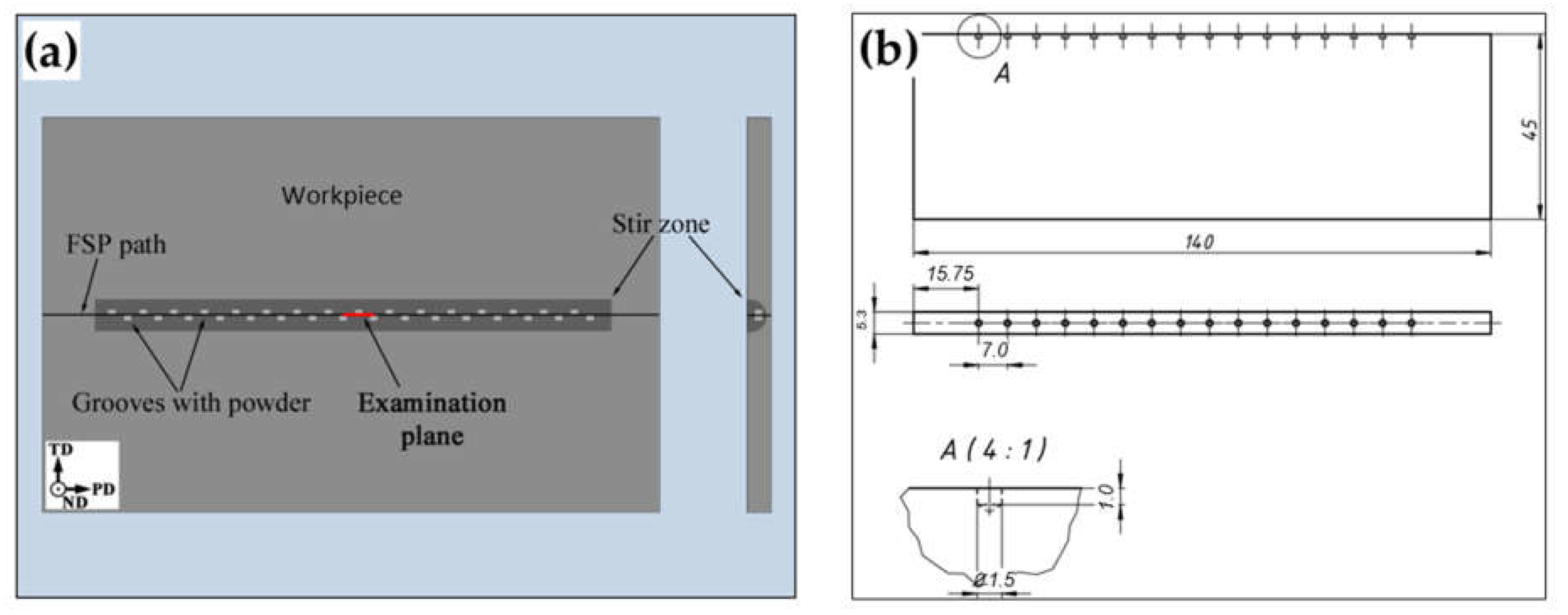
2. Materials and Methods
2.1. Materials
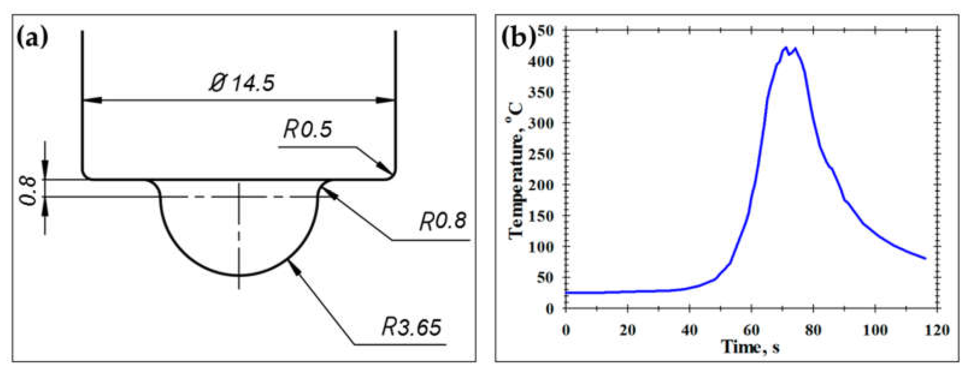
2.2. FSP Procedure
2.3. Microstructural Observations
3. Results and Discussion
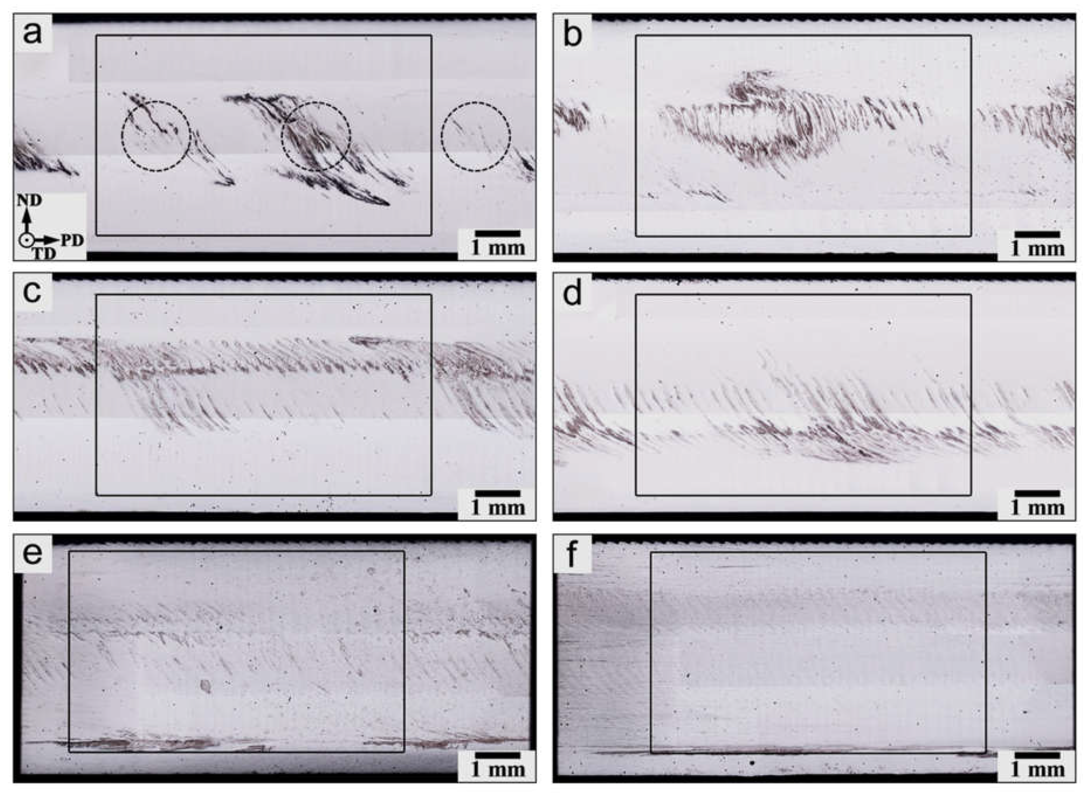
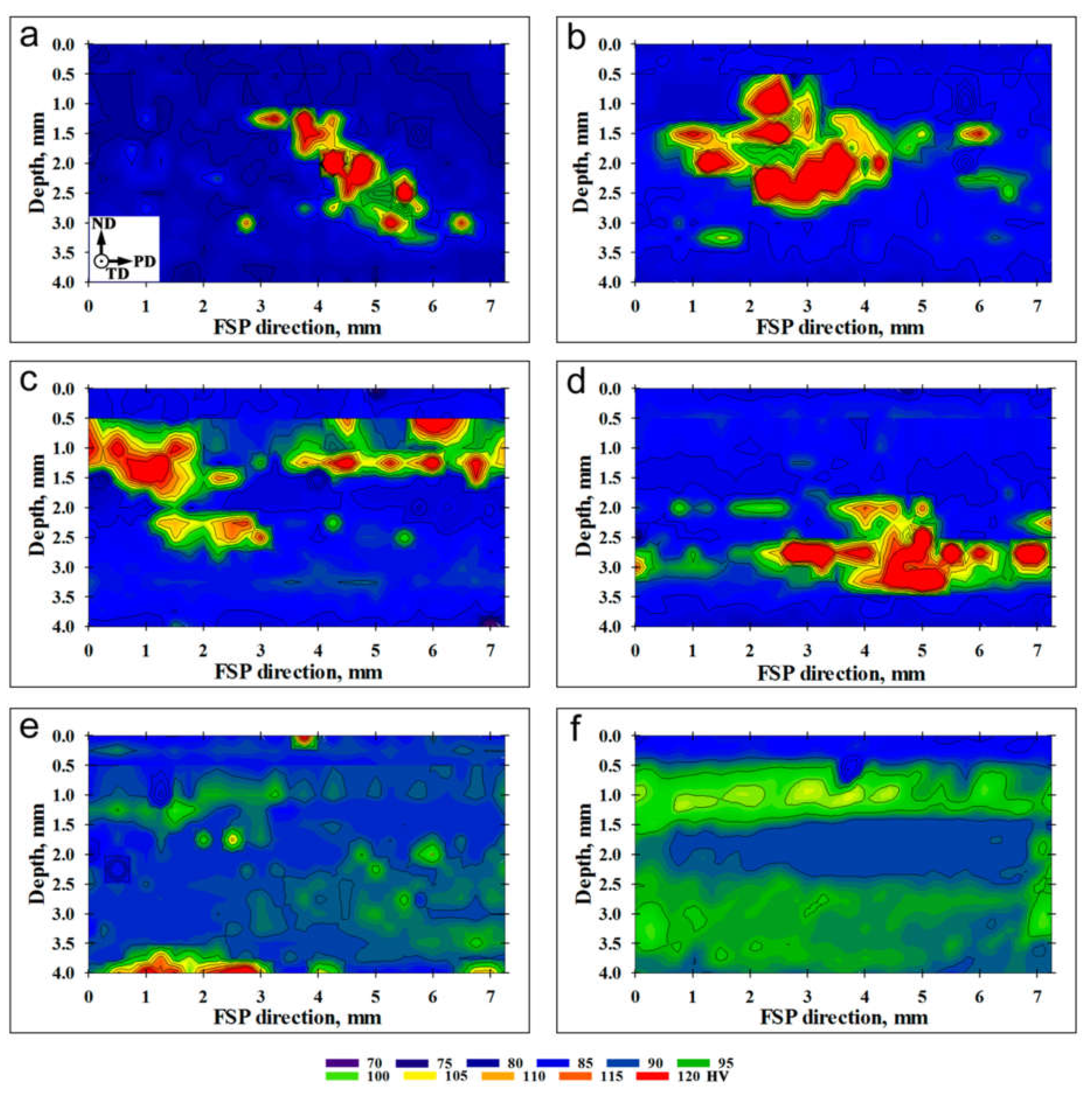
3.1. Macro-Scale Structure
3.2. Grain Structure: FSP without Using Reinforcing Particles
3.3. Effect of the Reinforcing Al2O3 Nanoscale Particles on Grain-Structure Evolution
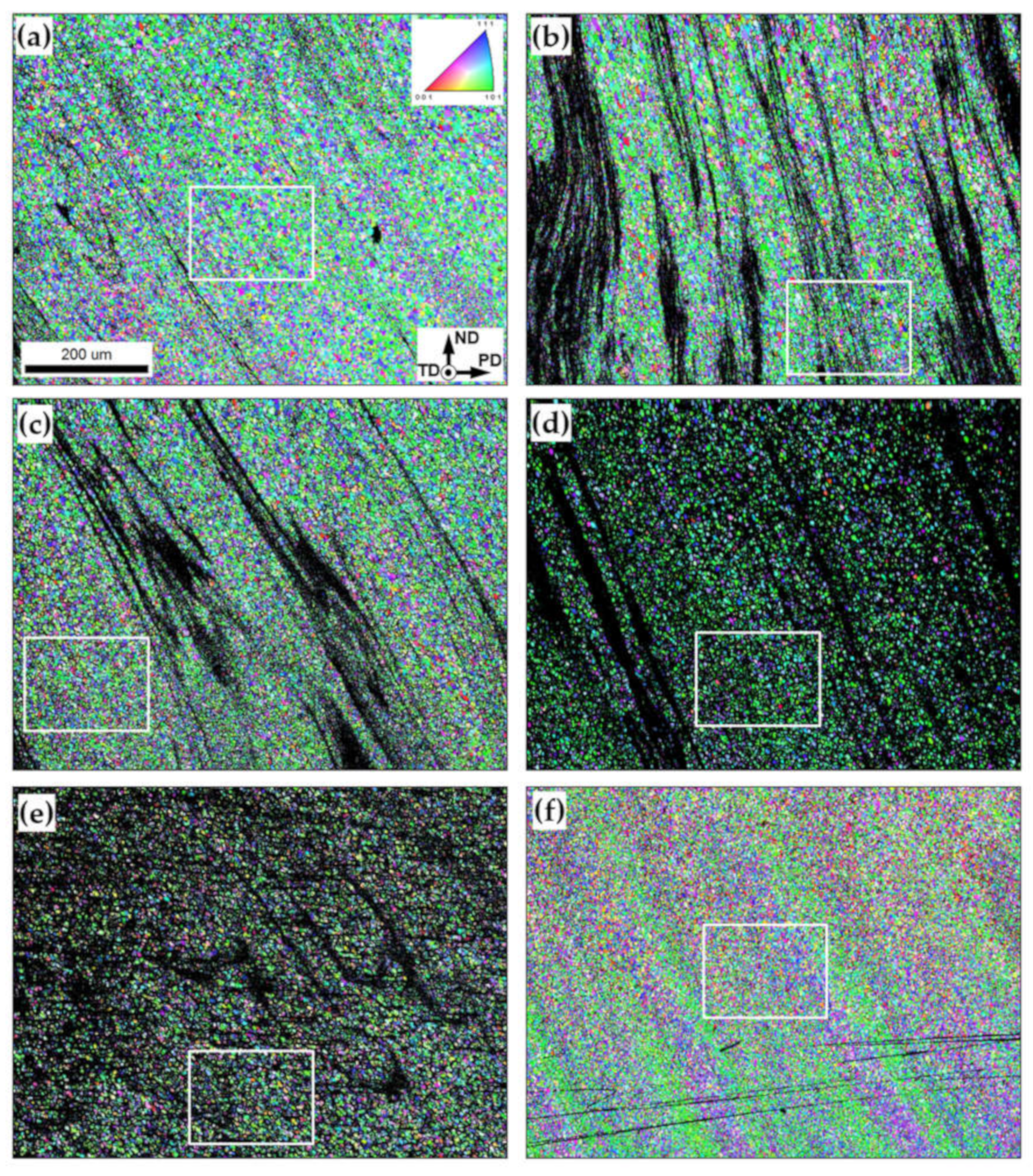
3.3.1. Low-Magnification Overview
3.3.2. Microstructure Morphology and Grain Size
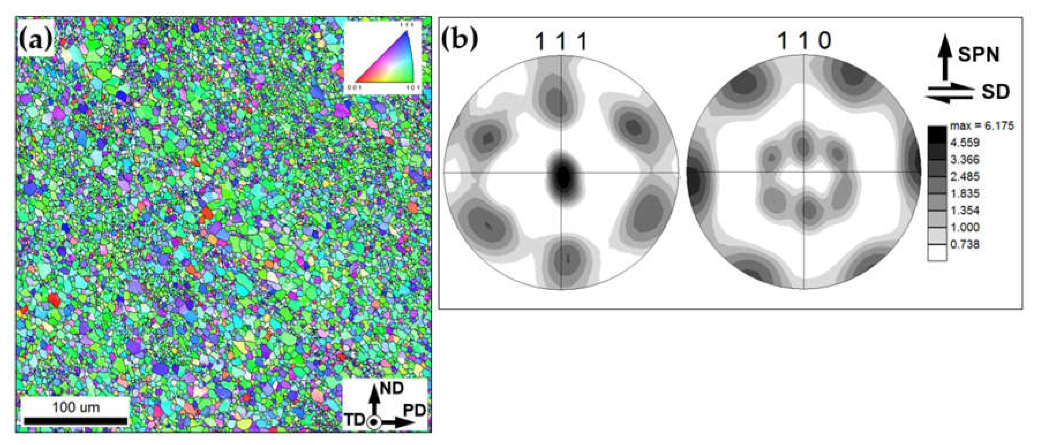
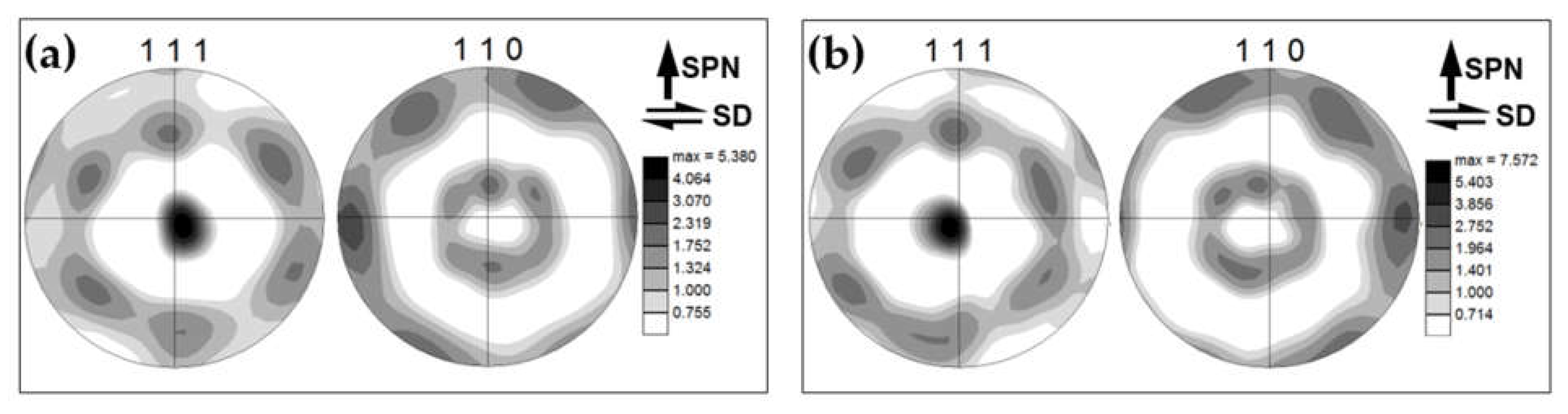
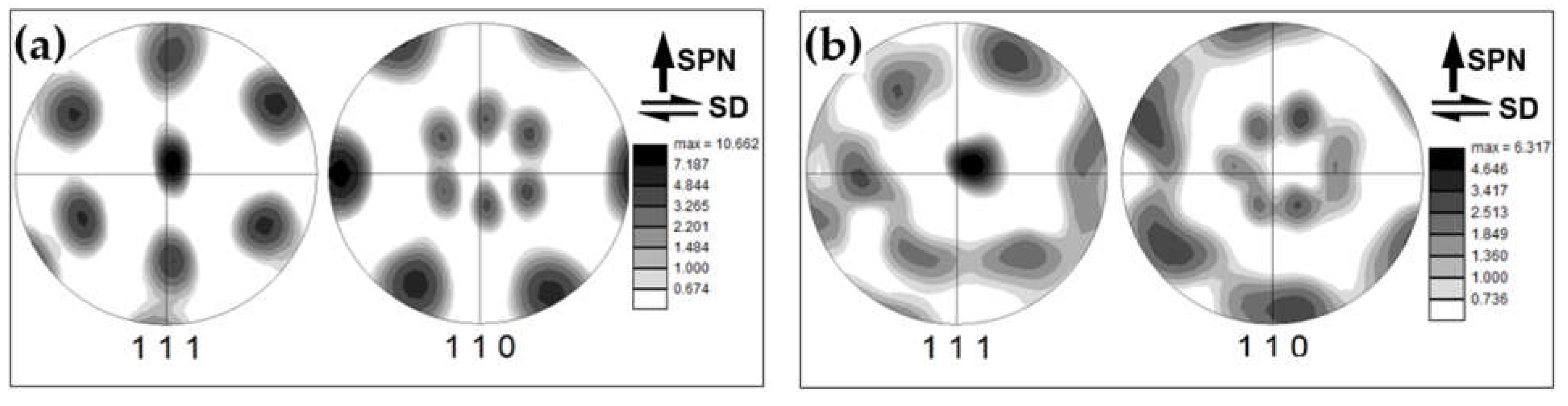
3.3.3. Crystallographic Texture
4. Conclusions
- (1)
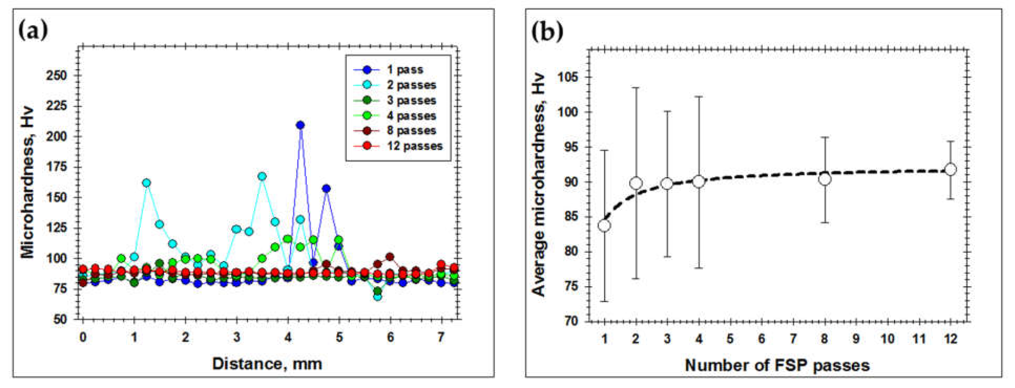
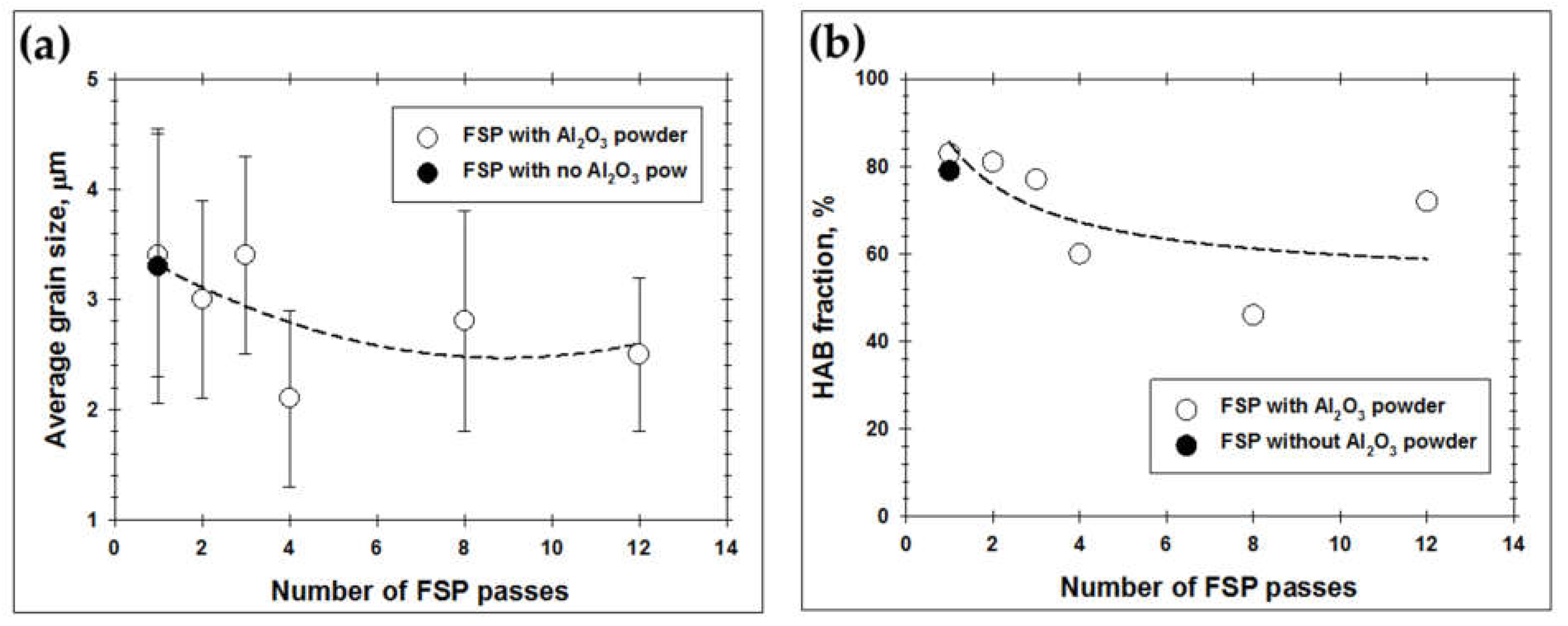
- Three or four FSP passes, which are often applied in practice, are not sufficient to provide a homogeneous dispersion of the reinforcing particles throughout the matrix material. It was found that the particles rapidly rearranged into the “onion-ring” structure, which was very stable against the subsequent FSP passes. In fact, the remnants of the “onion-ring” structure as well as the comparatively coarse-scale particle agglomerations in the bottom part of the processed material have survived even after 12 FSP passes.
- (2)
- The gradual dispersion of the reinforcing particles throughout the aluminum matrix promoted a subtle reduction in grain size and HAB fraction. These observations were suggested to originate from the combined effects of the particle-stimulated recrystallization as well as the retardation of grain-boundary migration and LAB-to-HAB transformation during FSP.
Author Contributions
Funding
Institutional Review Board Statement
Informed Consent Statement
Data Availability Statement
Acknowledgments
Conflicts of Interest
References
- Lloyd, D.J. Particle Reinforced Aluminum and Magnesium Matrix Composites. Int. Mater. Rev. 1994, 39, 1–23. [Google Scholar] [CrossRef]
- Mavhungu, S.T.; Akinlabi, E.T.; Onitiri, M.A.; Varachia, F.M. Aluminum Matrix Composites for Industrial Use: Advances and Trends. Proc. Manuf. 2017, 7, 178–182. [Google Scholar] [CrossRef]
- Torralba, J.M.; Costa, C.E.; Velasco, F. P/M Aluminum Matrix Composites: An Overview. J. Mater. Proc. Technol. 2003, 133, 203–206. [Google Scholar] [CrossRef]
- Mishra, R.S.; Ma, Z.Y.; Charit, I. Friction Stir Processing: A Novel Technique for Fabrication of Surface Composite. Mater. Sci. Eng. A 2003, 341, 307–310. [Google Scholar] [CrossRef]
- Sharma, V.; Prakash, U.; Manoj Kumar, B.V. Surface Composites by Friction Stir Processing: A Review. J. Mater. Proc. Technol. 2015, 224, 117–134. [Google Scholar] [CrossRef]
- Heidarzadeh, A.; Mironov, S.; Kaibyshev, R.; Cam, G.; Simar, A.; Gerlich, A.P.; Khodabakhshi, A.F.; Mostafaei, A.; Field, D.P.; Robson, J.D.; et al. Friction Stir Welding/Processing of Metals and Alloys: A Comprehensive Review on Microstructural Evolution. Prog. Mater. Sci. 2021, 117, 100752. [Google Scholar] [CrossRef]
- Gan, Y.X.; Solomon, D.; Reinbolt, M. Friction Stir Processing of Particle Reinforced Composite Materials. Materials 2010, 3, 329–350. [Google Scholar] [CrossRef] [Green Version]
- Tang, J.; Shen, Y.; Li, J. Influences of Friction Stir Processing Parameters on Microstructure and Mechanical Properties of SiC/Al Composites Fabricated by Multi-Pin Tool. J. Manuf. Proc. 2019, 38, 279–289. [Google Scholar] [CrossRef]
- Tang, J.; Shen, Y.; Li, J. Investigation of Microstructure and Mechanical Properties of SiC/Al Surface Composites Fabricated by Friction Stir Processing. Mater. Res. Express 2019, 6, 106576. [Google Scholar] [CrossRef]
- Moustafa, E.B.; Mikhaylovskaya, A.V.; Taha, M.A.; Mosleh, A.O. Improvement of the Microstructure and Mechanical Properties by Hybridizing the Surface of AA7075 by Hexagonal Boron Nitride with Carbide Particles Using the FSP Process. J. Mater. Res. Technol. 2022, 17, 1986–1999. [Google Scholar] [CrossRef]
- Sahraeinjad, S.; Izadi, H.; Haghshenas, M.; Gerlich, A.P. Fabrication of Metal Matrix Composites by Friction Stir Processing with Different Particles and Processing Parameters. Mater. Sci. Eng. A 2015, 626, 505–513. [Google Scholar] [CrossRef]
- Huang, C.W.; Aoh, J.N. Friction Stir Processing of Copper-Coated SiC Particulate-Reinforced Aluminum Matrix Composite. Materials 2018, 11, 599. [Google Scholar] [CrossRef] [Green Version]
- Khodabakhshi, F.; Nosko, M.; Gerlich, A.P. Dynamic Restoration and Crystallographic Texture of a Friction-Stir Processed Al-Mg-SiC Surface Nanocomposite. Mater. Sci. Technol. 2018, 34, 1773–1791. [Google Scholar] [CrossRef]
- Wojcicka, A.; Mroczka, K.; Kurtyka, P.; Binkowski, M.; Wrobel, Z. X-ray Microtomography Analysis of the Aluminum Alloy Composite Reinforced by SiC after Friction Stir Processing. J. Mater. Eng. Perform. 2014, 23, 3215–3221. [Google Scholar] [CrossRef] [Green Version]
- Wang, W.; Shi, Q.; Liu, P.; Li, H.; Li, T. A Novel Way to Produce Bulk SiCp Reinforced Aluminum Metal Matrix Composites by Friction Stir Processing. J. Mater. Proc. Technol. 2009, 209, 2099–2103. [Google Scholar] [CrossRef]
- Orlowska, M.; Pixner, F.; Hutter, A.; Enzinger, N.; Olejnik, L.; Lewandowska, M. Manufacturing of Coarse and Ultrafine-Grained Aluminum Matrix Composites Reinforced with Al2O3 Nanoparticles via Friction Stir Processing. J. Manuf. Proc. 2022, 80, 359–373. [Google Scholar] [CrossRef]
- Shafiei-Zarghani, A.; Kashani-Bozorg, S.F.; Zarei-Hanzaki, A. Wear Assessment of Al/Al2O3 Nanocomposite Surface Layer Produced Using Friction Stir Processing. Wear 2011, 270, 403–412. [Google Scholar] [CrossRef]
- Du, Z.; Tan, M.J.; Guo, J.F.; Bi, G.; Wei, J. Fabrication of a New Al-Al2O3-CNTs Composite Using Friction Stir Processing (FSP). Mater. Sci. Eng. A 2016, 667, 125–131. [Google Scholar] [CrossRef]
- Eskandari, H.; Taheri, R.; Khodabakhshi, F. Friction-Stir Processing of an AA8026-TiB2-Al2O3 Hybrid Nanocomposite. Mater. Sci. Eng. A 2016, 660, 84–96. [Google Scholar] [CrossRef]
- Moustafa, E. Effect of Multi-Pass Friction Stir Processing on Mechanical Properties for AA2024/Al2O3 Nanocomposites. Materials 2017, 10, 1053. [Google Scholar] [CrossRef] [Green Version]
- AbuShanab, W.S.; Moustafa, E.B. Effects of Friction Stir Processing Parameters on the Wear Resistance and Mechanuical Properties of Fabricated Metal Matrix Nanocomposites (MMNCs) Surface. J. Mater. Res. Technol. 2020, 9, 7460–7471. [Google Scholar] [CrossRef]
- Moustafa, E.B. Dynamic Characteristics Study for Surface Composite of AMMNCs Matrix Fabricated by Friction Stir Process. Materials 2018, 11, 1240. [Google Scholar] [CrossRef] [PubMed] [Green Version]
- Shafiei-Zarghani, A.; Kashani-Bozorg, S.F.; Zarei-Hanzaki, A. Microstructures and Mechanical Properties of Al/Al2O3 Surface Nano-Composite Layer Produced by Friction Stir Processing. Mater. Sci. Eng. A 2009, 500, 84–91. [Google Scholar] [CrossRef]
- Mazaheri, Y.; Karimzadeh, F.; Enayati, M.H. A Novel Technique for Development of A356/Al2O3 Surface Nanocomposite by Friction Stir Processing. J. Mater. Proc. Technol. 2011, 211, 1614–1619. [Google Scholar] [CrossRef]
- Mazaheri, Y.; Karimzadeh, F.; Enayati, M.H. Tribological Behavior of A356/Al2O3 Surface Nanocomposite Prepared by Friction Stir Processing. Metall. Mater. Trans. A 2014, 45, 2250–2259. [Google Scholar] [CrossRef]
- Rana, H.; Badheka, V. Influence of Friction Stir Processing Conditions on the Manufacturing of Al-Mg-Zn-Cu Alloy/Boron Carbide Surface Composite. J. Mater. Proc. Technol. 2018, 255, 795–807. [Google Scholar] [CrossRef]
- Pariyar, A.; Perugu, C.; Toth, L.; Kailas, S. Microstructure and Mechanical Behavior of Polymer-Derived in-Situ Ceramic Reinforced Lightweight Aluminum Matrix Composite. J. Alloy. Compd. 2021, 880, 160430. [Google Scholar] [CrossRef]
- Sharma, A.; Gupta, G.; Paul, J. A Comprehensive Review on the Dispersion and Survivability Issues of Carbon Nanotubes in Al/CNT Nanocomposites Fabricated via Friction Stir Processing. Carbon Lett. 2021, 31, 339–370. [Google Scholar] [CrossRef]
- Mahmoud, E.R.I.; Tash, M.M. Characterization of Aluminum-Based-Surface Matrix Composites with Iron and Iron Oxide Fabricated by Friction Stir Processing. Materials 2016, 23, 505. [Google Scholar] [CrossRef] [Green Version]
- Papantoniou, I.G.; Markopoulos, A.P.; Manolakos, D.E. A New Approach in Surface Modification and Surface Hardening of Aluminum Alloys Using Friction Stir Process: Cu-Reinforced AA5083. Materials 2020, 13, 1278. [Google Scholar] [CrossRef] [Green Version]
- Guo, L.; Liu, Y.; Shen, K.; Song, C.; Yang, M.; Kim, K.; Wang, W. Enhancing Corrosion and Wear Resistance of AA6061 by Friction Stir Processing with Fe78Si9B13 Glass Particles. Materials 2015, 8, 5084–5097. [Google Scholar] [CrossRef] [PubMed]
- Rubtsov, V.; Chumaevskii, A.; Gusarova, A.; Knyazhev, E.; Gurianov, D.; Zykova, A.; Kalashnikova, T.; Cheremnov, A.; Savchenko, N.; Vorontsov, A.; et al. Macro- and Microstructure of In-Situ Composites Prepared by Friction Stir Processing of AA5056 Admixed with Copper Powders. Materials 2023, 16, 1070. [Google Scholar] [CrossRef]
- Chumaevskii, A.; Zykova, A.; Sudarikov, A.; Knyazhev, E.; Savchenko, N.; Gubanov, A.; Moskvichev, E.; Gurianov, D.; Nikolaeva, A.; Vorontsov, A.; et al. In-Situ Al-Mg Alloy Base Composite Reinforced by Oxides and Intermetallic Compounds Resulted from Decomposition of ZrW2O8 during Multipass Friction Stir Processing. Materials 2023, 16, 817. [Google Scholar] [CrossRef]
- Adams, B.L.; Wright, S.I.; Kunze, K. Orientation imaging: The Emergence of a New Microscopy. Metal. Tans. A 1993, 24, 819–831. [Google Scholar] [CrossRef]
- Humphreys, F.J. Quantitative Metallography by Electron Back-Scattered Diffraction. J. Microsc. 1999, 195, 170–185. [Google Scholar] [CrossRef]
- Zhang, C.; Hu, X.; Lu, P. Fatigue and Hardness Effects of a Thin Buffer Layer on the Heat Affected Zone of a Weld Repaired Bisplate80. J. Mater. Proc. Technol. 2012, 212, 393–401. [Google Scholar] [CrossRef]
- Krishnan, K.N. On the Formation of Onion Rings in Friction Stir Welds. Mater. Sci. Eng. A 2002, 327, 246–251. [Google Scholar] [CrossRef]
- Abraham, S.J.; Dinaharan, I.; Selvam, J.D.R.; Akinlabi, E.T. Microstructural Characterization of Vanadium Particles Reinforced AA6063 Aluminum Matrix Composites via Friction Stir Processing with Improved Tensile Strength and Appreciable Ductility. Compos. Commun. 2019, 12, 54–58. [Google Scholar] [CrossRef]
- Khan, M.; Rehman, A.; Aziz, T.; Naveed, K.; Ahmad, I.; Subhani, T. Cold Formability of Friction Stir Processed Aluminum Composites Containing Carbon Nanotubes and Boron Carbide Particles. Mater. Sci. Eng. A 2017, 701, 382–388. [Google Scholar] [CrossRef]
- Arab, S.M.; Karimi, S.; Jahromi, S.A.J.; Javadpour, S.; Zebarjad, S.M. Fabrication of Novel Fiber Reinforced Aluminum Composites by Friction Stir Processing. Mater. Sci. Eng. A 2015, 632, 50–57. [Google Scholar] [CrossRef]
- Jeon, C.H.; Jeong, Y.H.; Seo, J.J.; Tien, H.N.; Hong, S.T.; Yum, Y.J.; Hur, S.H.; Lee, K.J. Material Properties of Graphene/Aluminum Metal Matrix Composites Fabricated by Friction Stir Processing. Int. J. Precis. Eng. Manuf. 2014, 15, 1235–1239. [Google Scholar] [CrossRef]
- Liu, Q.; Ke, L.; Liu, F.; Huang, C.; Xing, L. Microstructure and Mechanical Property of Multi-Walled Carbon Nanotubes Reinforced Aluminum Matrix Composites Fabricated by Friction Stir Processing. Mater. Des. 2013, 45, 343–348. [Google Scholar] [CrossRef]
- Lee, I.S.; Hsu, C.J.; Chen, C.F.; Ho, N.J.; Kao, P.W. Particle-Reinforced Aluminum Matrix Composites Produced from Powder Mixtures via Friction Stir Processing. Composit. Sci. Technol. 2011, 71, 693–698. [Google Scholar] [CrossRef]
- Nakama, D.; Katoh, K.; Tokisue, H. Effect of Probe Shape on Dispersibility of Alumina Particles into 6061 Aluminum Alloy by Friction Stir Processing. J. Jap. Inst. Light Metal. 2011, 61, 95–99. [Google Scholar] [CrossRef] [Green Version]
- Fonda, R.W.; Bingert, J.F.; Colligan, K.J. Development of Grain Structure during Friction Stir Welding. Scripta Mater. 2004, 51, 243–248. [Google Scholar] [CrossRef]
- Mironov, S.; Inagaki, K.; Sato, Y.S.; Kokawa, H. Effect of Welding Temperature on Microstructure of Friction-Stir Welded Aluminum Alloy. Metall. Mater. Trans. A 2015, 46, 783–790. [Google Scholar] [CrossRef]
- Humphreys, F.J.; Prangnell, P.B.; Bowen, J.R.; Gholinia, A.; Harris, C. Developing Stable Fine-Grain Microstructures by Large Strain Deformation. Philos. Trans. R. Soc. Lond. A 1999, 357, 1663–1681. [Google Scholar] [CrossRef]
- Prangnell, P.B.; Bowen, J.R.; Apps, P.J. Ultra-Fine Grain Structures in Aluminum Alloys by Severe Plastic Deformation Procesing. Mater. Sci. Eng. A 2004, 375–377, 178–185. [Google Scholar] [CrossRef]
- Prangnell, P.B.; Heason, C.P. Grain Structure Formation during Friction Stir Welding Observed by the “Stop Action Technique”. Acta Mater. 2005, 53, 3179–3192. [Google Scholar] [CrossRef]
- Fonda, R.W.; Knipling, K.E. Texture Development in Friction Stir Welds. Sci. Technol. Weld. Join. 2011, 16, 288–294. [Google Scholar] [CrossRef]
- Moustafa, E.B.; AbuShanab, W.S.; Ghandourah, E.; Taha, M.A. Microstructural, Mechanical and Thermal Properties Evaluation of AA6061/Al2O3-BN Hybrid and Mono Nanocomposite Surface. J. Mater. Res. Technol. 2020, 9, 15486–15495. [Google Scholar] [CrossRef]
- Moustafa, E.B.; Melaibari, A.; Alsoruji, G.; Khalil, A.M.; Mosleh, A.O. Tribological and Mechanical Characteristics of AA5083 Alloy Reinforced by Hybridising Heavy Ceramic Particles Ta2C & VC with Light GNP and Al2O3 Nanoparticles. Ceramic Int. 2022, 48, 4710–4721. [Google Scholar] [CrossRef]
- Moustafa, E.B.; Abushanab, W.S.; Melaibari, A.; Yakovtseva, O.; Mosleh, A.O. The Effectiveness of Incorporating Hybrid Reinforcement Nanoparticles in the Enhancement of the Tribological Behavior of Aluminum Metal Matrix Composites. JOM 2021, 73, 4338–4348. [Google Scholar] [CrossRef]
- Abushanab, W.S.; Moustafa, E.B.; Melaibari, A.A.; Kotov, A.D.; Mosleh, A.O. A Novel Comparative Study Based on the Economic Feasibility of the Ceramic Nanoparticles Role’s in Improving the Properties of the AA5250 Nanocomposites. Coatings 2021, 11, 977. [Google Scholar] [CrossRef]


Disclaimer/Publisher’s Note: The statements, opinions and data contained in all publications are solely those of the individual author(s) and contributor(s) and not of MDPI and/or the editor(s). MDPI and/or the editor(s) disclaim responsibility for any injury to people or property resulting from any ideas, methods, instructions or products referred to in the content. |
© 2023 by the authors. Licensee MDPI, Basel, Switzerland. This article is an open access article distributed under the terms and conditions of the Creative Commons Attribution (CC BY) license (https://creativecommons.org/licenses/by/4.0/).
Share and Cite
Malopheyev, S.S.; Zuiko, I.S.; Mironov, S.Y.; Kaibyshev, R.O. Microstructural Aspects of the Fabrication of Al/Al2O3 Composite by Friction Stir Processing. Materials 2023, 16, 2898. https://doi.org/10.3390/ma16072898
Malopheyev SS, Zuiko IS, Mironov SY, Kaibyshev RO. Microstructural Aspects of the Fabrication of Al/Al2O3 Composite by Friction Stir Processing. Materials. 2023; 16(7):2898. https://doi.org/10.3390/ma16072898
Chicago/Turabian StyleMalopheyev, Sergey S., Ivan S. Zuiko, Sergey Yu. Mironov, and Rustam O. Kaibyshev. 2023. "Microstructural Aspects of the Fabrication of Al/Al2O3 Composite by Friction Stir Processing" Materials 16, no. 7: 2898. https://doi.org/10.3390/ma16072898