

An Investigation into the Potential of Turning Induced Deformation Technique for Developing Porous Magnesium and Mg-SiO2 Nanocomposite


Abstract
:1. Introduction
2. Materials and Methods
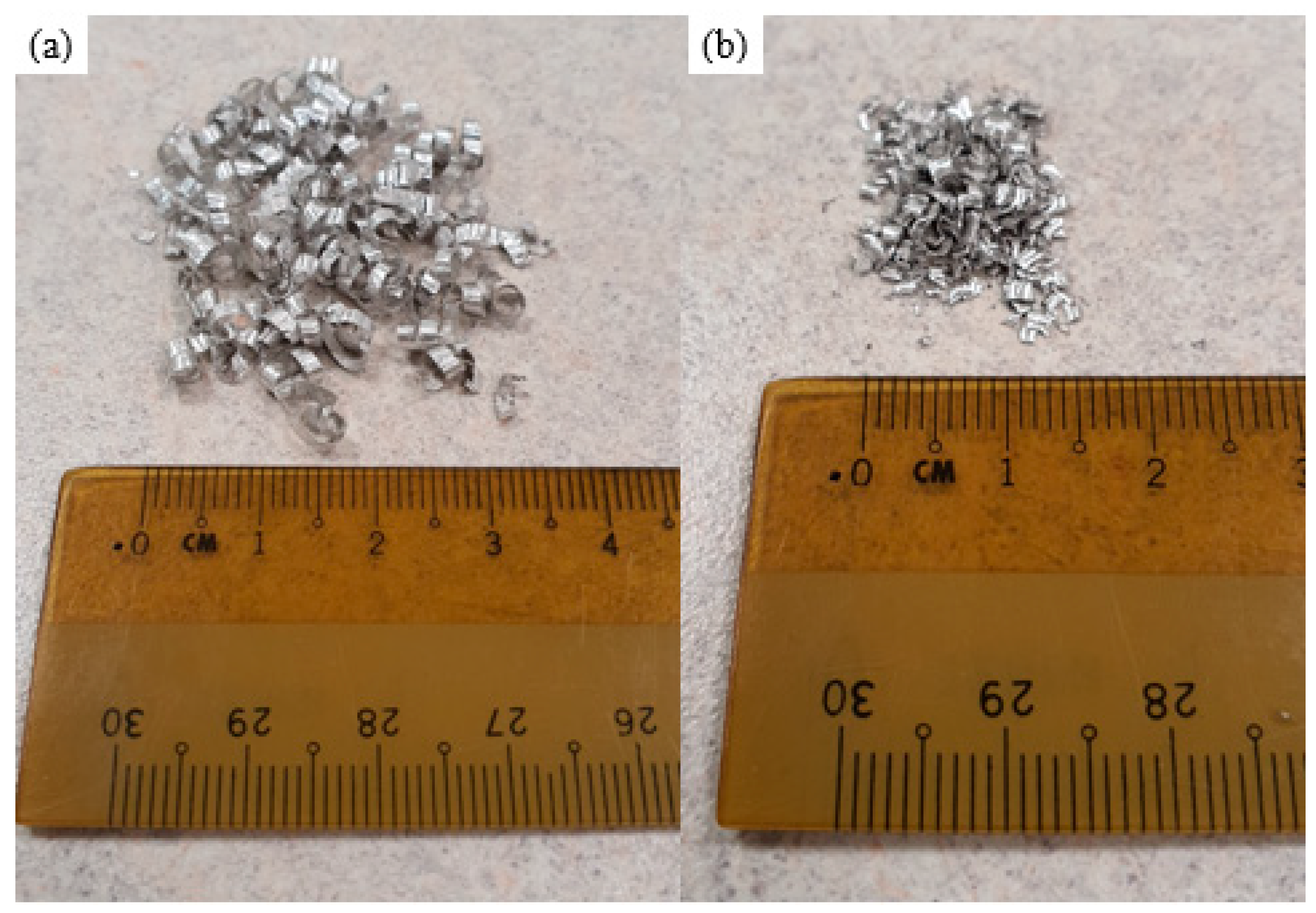
2.1. Materials
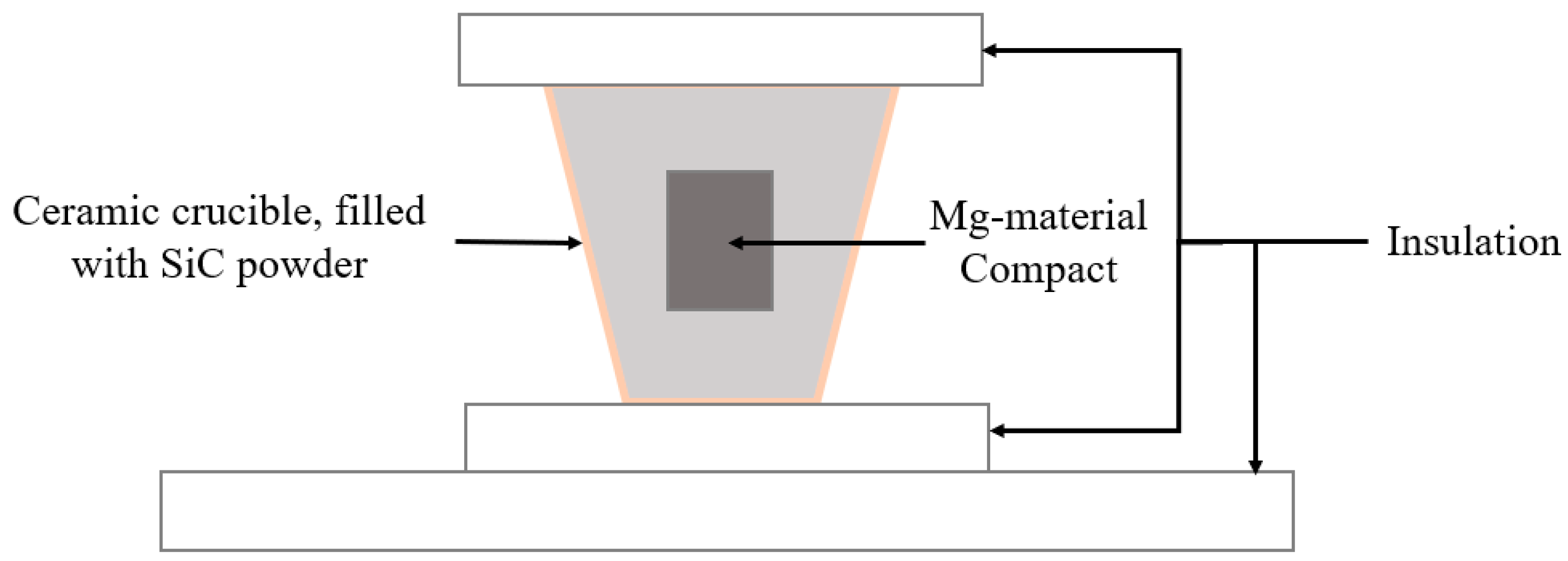
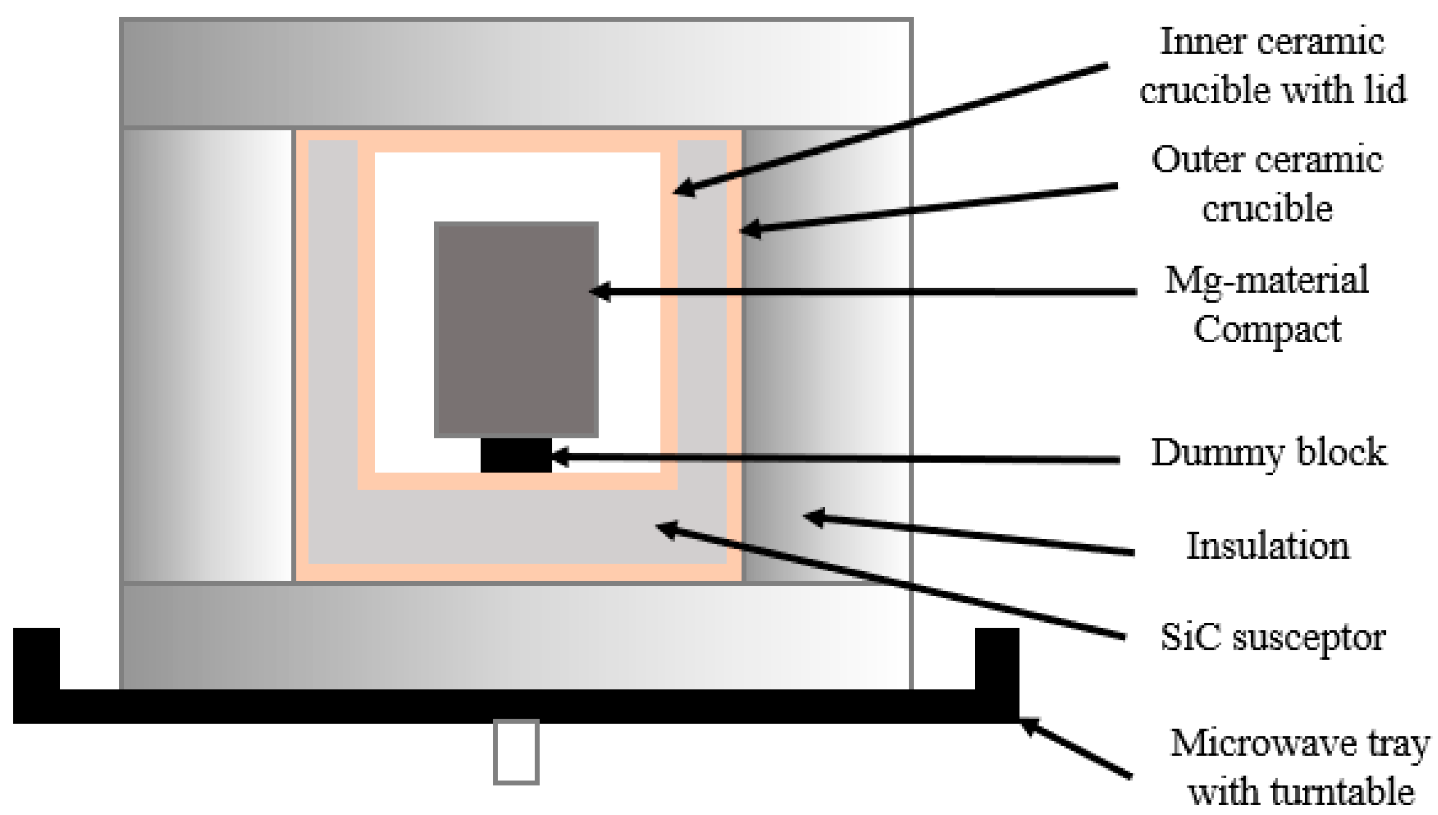
2.2. Synthesis
- Microwave sintering using a Sharp R-898C(S) 900W microwave for 18 min to reach 525 °C, with the setup cooling down inside the microwave chamber to ambient temperature.
- Furnace sintering using an Elite BAF7/15 furnace with a temperature of 520 °C at 20°/min temperature increase with a holding time of 2 h, with the setup cooling down without the lid until the Mg material compact reaches ambient temperature.
2.3. Materials Characterisation
2.3.1. Density and Porosity
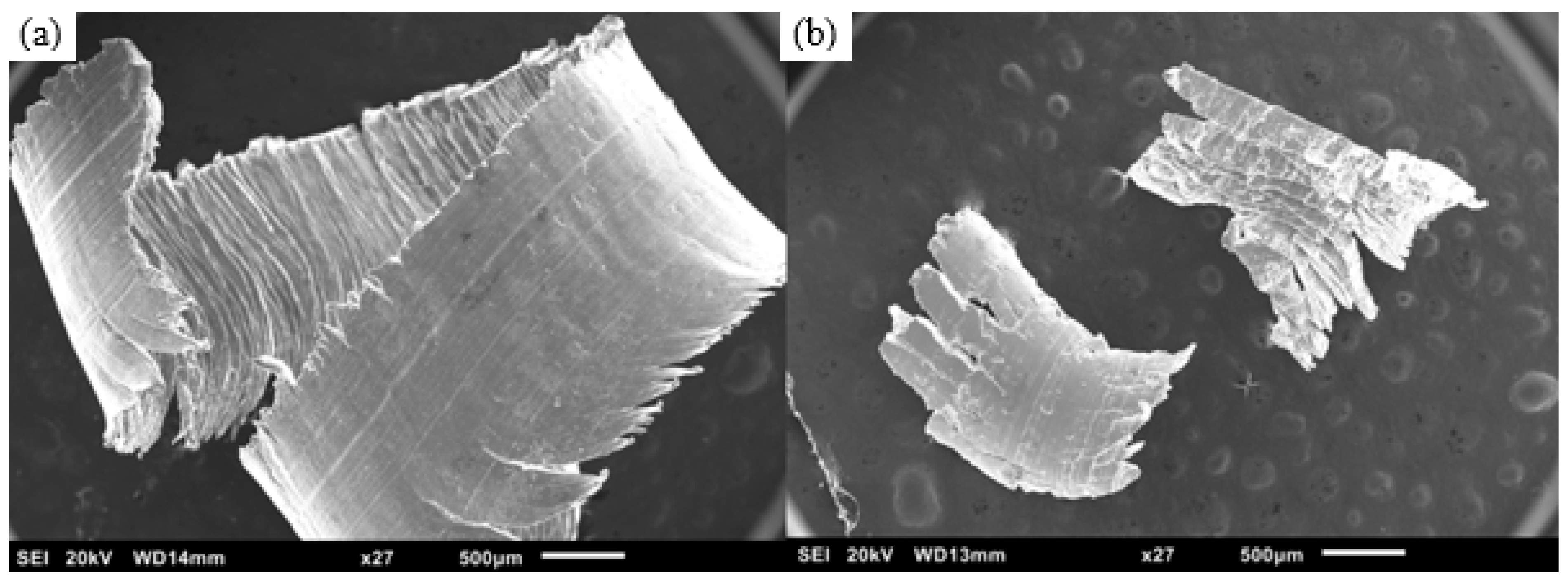
2.3.2. Microstructure
2.3.3. X-ray Diffraction
2.3.4. Grain Size
2.3.5. Mechanical Properties
3. Results and Discussion
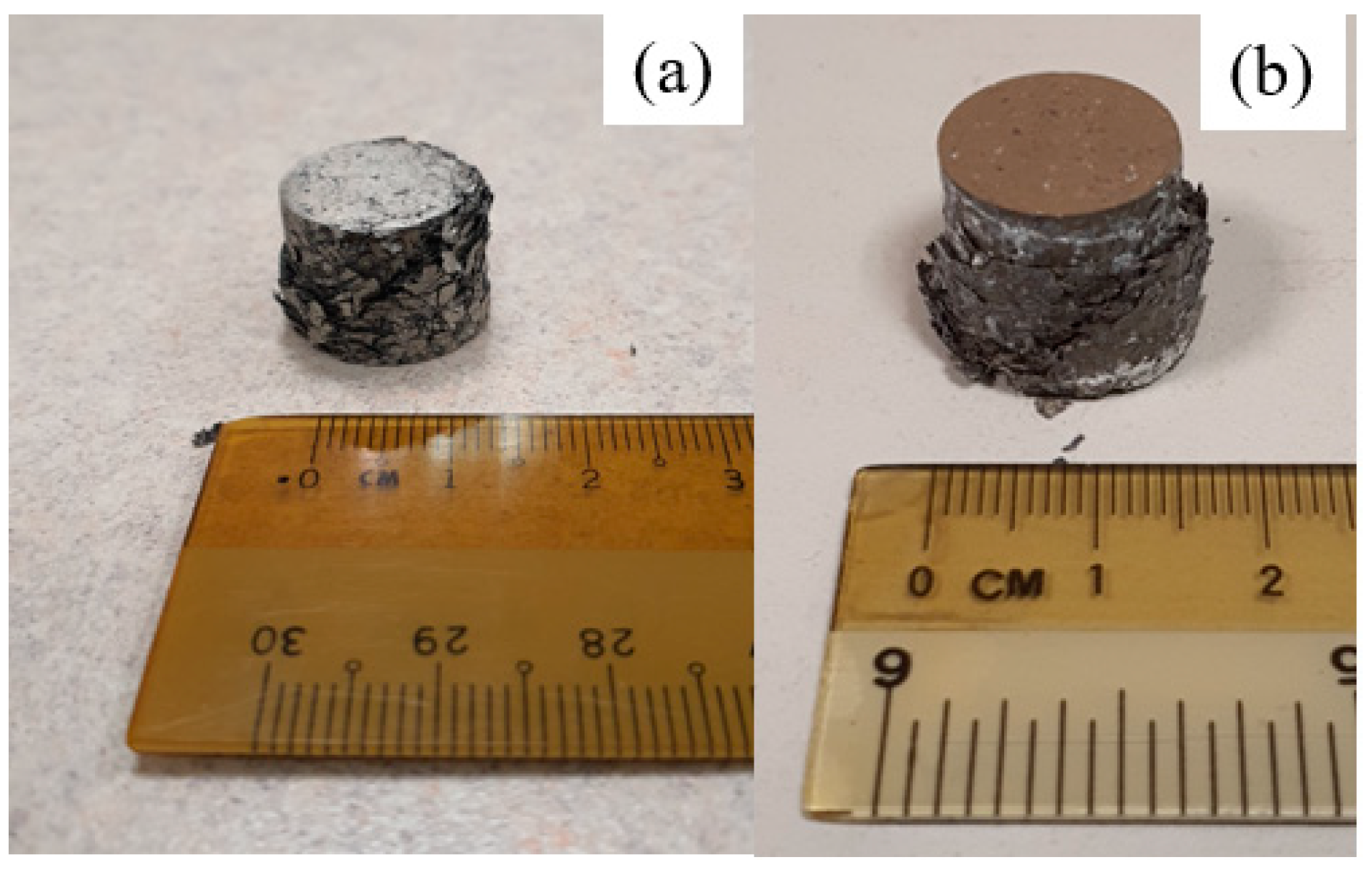
3.1. Synthesis
3.2. Density and Porosity
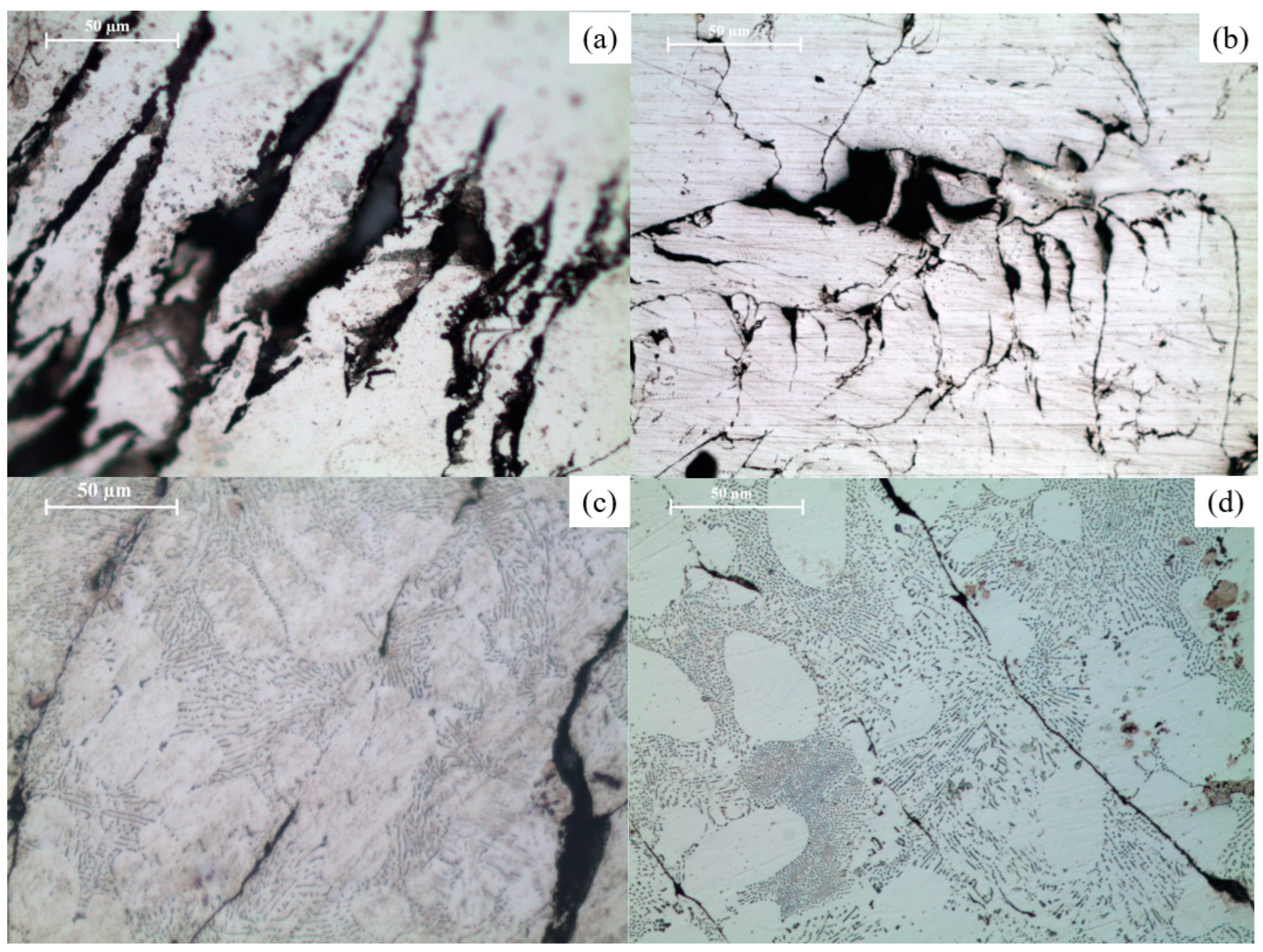
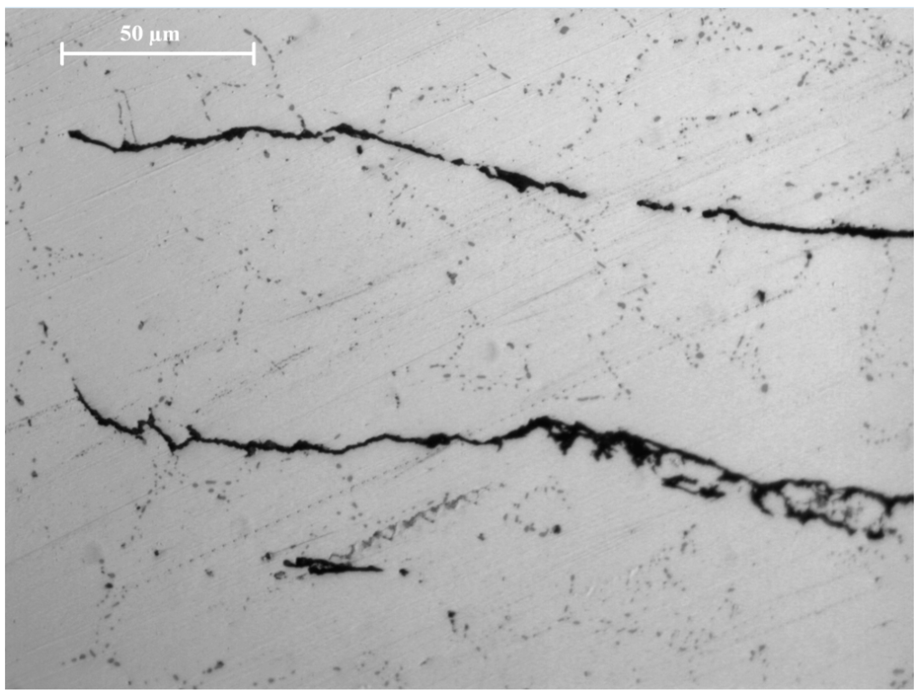
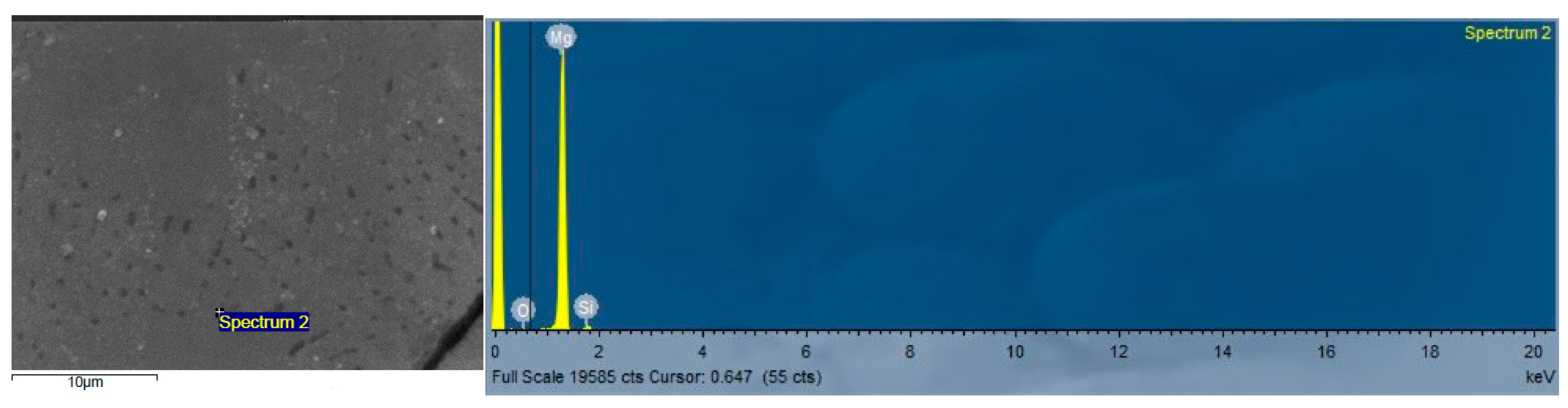
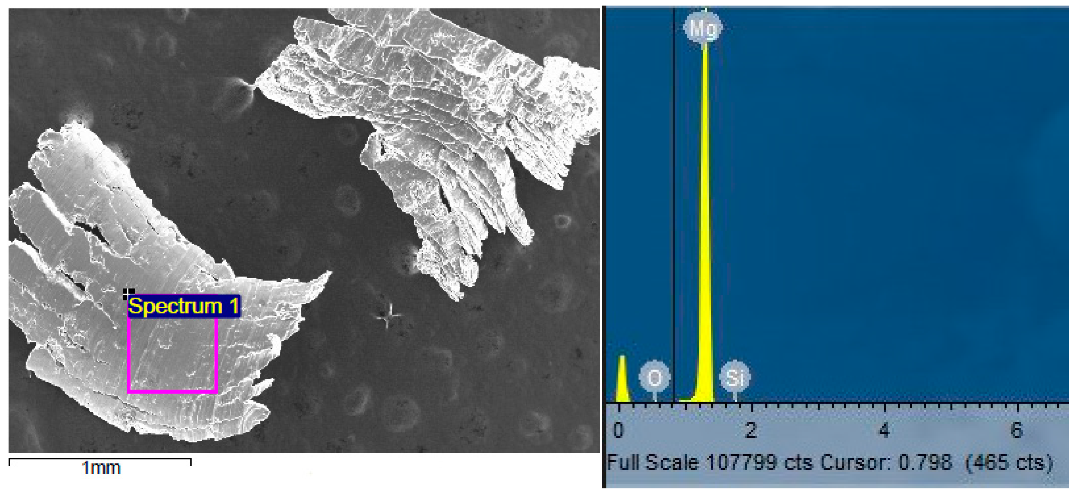
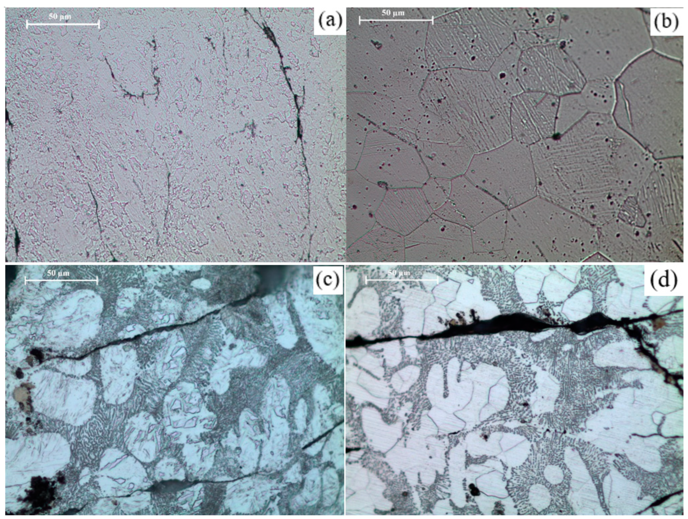
3.3. Microstructure
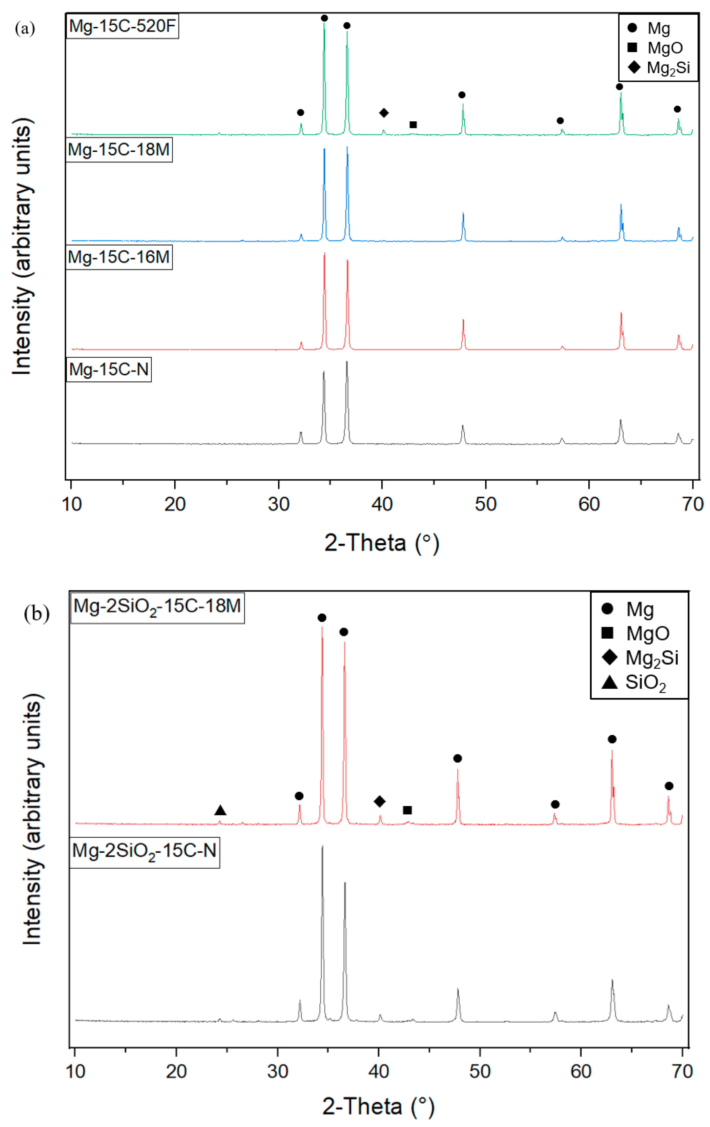
3.4. X-ray Diffraction
3.5. Grain Size
3.6. Mechanical Properties
3.6.1. Microhardness Measurements
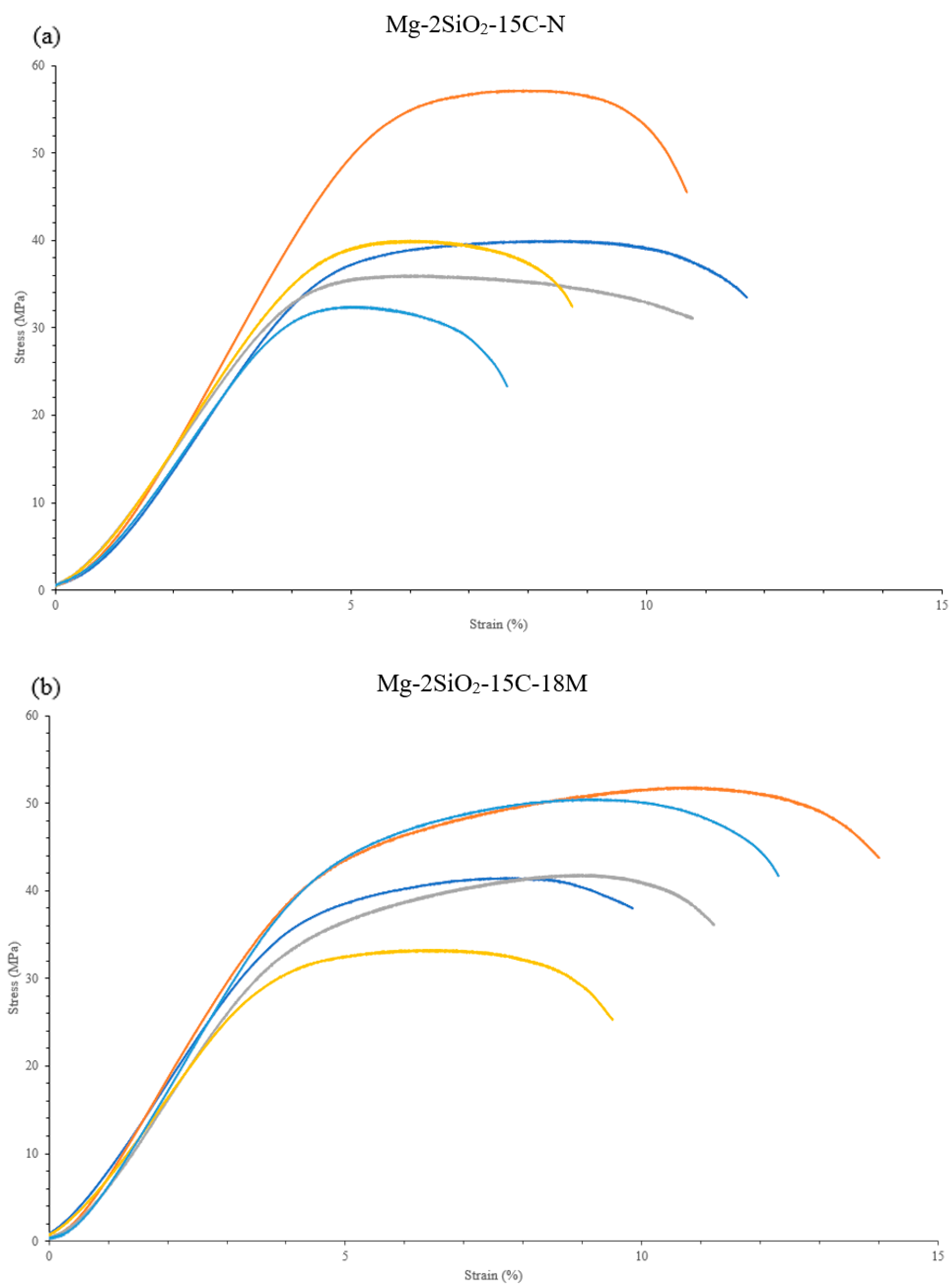
3.6.2. Compressive Properties
4. Discussion
4.1. Synthesis
4.2. Density and Porosity
4.3. Microstructure
4.4. X-ray Diffraction
4.5. Grain Size
4.6. Mechanical Properties
4.6.1. Microhardness Measurements
4.6.2. Compressive Properties
5. Concluding Remarks and Future Work
- Porous TID Mg materials have shown comparable compressive response as well as other properties to other recent forms of porous Mg materials synthesised using different methods in the literature.
- Mg-2SiO2 shows potential as a better property-matching material with reference to human cancellous bone.
- Microwave sintering resulted in materials with the best consistency in mechanical response, and also enhances the compressive properties of porous TID Mg-2SiO2.
Author Contributions
Funding
Institutional Review Board Statement
Informed Consent Statement
Data Availability Statement
Conflicts of Interest
References
- Gianella, S.; Malandruccolo, A. Aerospace Alloys. In Topics in Minings, Metallurgy and Materials Engineering; Bergmann, C.P., Ed.; Springer: New York City, NY, USA, 2020; pp. 109–124. [Google Scholar]
- Chouirfa, H.; Bouloussa, H.; Migonney, V.; Falentin-Daudré, C. Review of titanium surface modification techniques and coatings for antibacterial applications. Acta Biomater. 2019, 83, 37–54. [Google Scholar] [CrossRef]
- Jin, W.; Chu, P.K. Orthopedic Implants. In Encyclopedia of Biomedical Engineering; Narayan, R., Ed.; Elsevier: Oxford, UK, 2019; pp. 425–439. [Google Scholar] [CrossRef]
- Pacheco, K.A. Allergy to Surgical Implants. Clin. Rev. Allergy Immunol. 2019, 56, 72–85. [Google Scholar] [CrossRef] [PubMed]
- Levine, B. A New Era in Porous Metals: Applications in Orthopaedics. Adv. Eng. Mater. 2008, 10, 788–792. [Google Scholar] [CrossRef]
- Karageorgiou, V.; Kaplan, D. Porosity of 3D biomaterial scaffolds and osteogenesis. Biomaterials 2005, 26, 5474–5491. [Google Scholar] [CrossRef]
- Atlas Foundry Company, Inc. Mechanical Properties of Gray Iron—Damping Capacity. Available online: http://www.atlasfdry.com/grayiron-damping.htm (accessed on 16 January 2023).
- Li, B.; Lavernia, E.J. Spray Forming of MMCs. In Comprehensive Composite Materials, 1st ed.; Kelly, A., Zweben, C., Eds.; Elsevier: Oxford, UK, 2000; Volume 3, pp. 617–653. [Google Scholar]
- Xie, Z.-k.; Tane, M.; Hyun, S.-k.; Okuda, Y.; Nakajima, H. Vibration–damping capacity of lotus-type porous magnesium. Mater. Sci. Eng. A 2006, 417, 129–133. [Google Scholar] [CrossRef]
- Geng, F.; Tan, L.; Zhang, B.; Wu, C.; He, Y.; Yang, J.; Yang, K. Study on β-TCP Coated Porous Mg as a Bone Tissue Engineering Scaffold Material. J. Mater. Sci. Technol. 2009, 25, 123–129. [Google Scholar]
- Yazdimamaghani, M.; Razavi, M.; Vashaee, D.; Moharamzadeh, K.; Boccaccini, A.R.; Tayebi, L. Porous magnesium-based scaffolds for tissue engineering. Mater. Sci. Eng. C 2017, 71, 1253–1266. [Google Scholar] [CrossRef] [Green Version]
- Md. Saad, A.P.; Jasmawati, N.; Harun, M.N.; Abdul Kadir, M.R.; Nur, H.; Hermawan, H.; Syahrom, A. Dynamic degradation of porous magnesium under a simulated environment of human cancellous bone. Corros. Sci. 2016, 112, 495–506. [Google Scholar] [CrossRef]
- Hao, G.L.; Han, F.S.; Li, W.D. Processing and mechanical properties of magnesium foams. J. Porous Mater. 2009, 16, 251–256. [Google Scholar] [CrossRef]
- Čapek, J.; Vojtěch, D. Effect of sintering conditions on the microstructural and mechanical characteristics of porous magnesium materials prepared by powder metallurgy. Mater. Sci. Eng. C 2014, 35, 21–28. [Google Scholar] [CrossRef]
- Wen, C.E.; Mabuchi, M.; Yamada, Y.; Shimojima, K.; Chino, Y.; Asahina, T. Processing of biocompatible porous Ti and Mg. Scr. Mater. 2001, 45, 1147–1153. [Google Scholar] [CrossRef]
- Seyedraoufi, Z.S.; Mirdamadi, S. Synthesis, microstructure and mechanical properties of porous Mg–Zn scaffolds. J. Mech. Behav. Biomed. Mater. 2013, 21, 1–8. [Google Scholar] [CrossRef]
- Renders, G.A.P.; Mulder, L.; van Ruijven, L.J.; van Eijden, T.M.G.J. Porosity of human mandibular condylar bone. J. Anat. 2007, 210, 239–248. [Google Scholar] [CrossRef]
- Mour, M.; Das, D.; Winkler, T.; Hoenig, E.; Mielke, G.; Morlock, M.M.; Schilling, A.F. Advances in Porous Biomaterials for Dental and Orthopaedic Applications. Materials 2010, 3, 2947–2974. [Google Scholar] [CrossRef] [Green Version]
- Das, P.; Kumar, T.S.S.; Sahu, K.; Gollapudi, S. Corrosion, Stress Corrosion Cracking and Corrosion Fatigue Behavior of Magnesium Alloy Bioimplants. Unpublished. 2021. [Google Scholar]
- Arifvianto, B.; Zhou, J. Fabrication of Metallic Biomedical Scaffolds with the Space Holder Method: A Review. Materials 2014, 7, 3588–3622. [Google Scholar] [CrossRef] [Green Version]
- Witte, F.; Fischer, J.; Nellesen, J.; Crostack, H.-A.; Kaese, V.; Pisch, A.; Beckmann, F.; Windhagen, H. In vitro and in vivo corrosion measurements of magnesium alloys. Biomaterials 2006, 27, 1013–1018. [Google Scholar] [CrossRef] [PubMed]
- Witte, F.; Ulrich, H.; Palm, C.; Willbold, E. Biodegradable magnesium scaffolds: Part II: Peri-implant bone remodeling. J. Biomed. Mater. Res. Part A 2007, 81, 757–765. [Google Scholar] [CrossRef]
- Cvrček, L.; Horáková, M. Chapter 14—Plasma Modified Polymeric Materials for Implant Applications. In Non-Thermal Plasma Technology for Polymeric Materials; Thomas, S., Mozetič, M., Cvelbar, U., Špatenka, P., Praveen, K.M., Eds.; Elsevier: Oxford, UK, 2019; pp. 367–407. [Google Scholar] [CrossRef]
- Cheng, M.-Q.; Wahafu, T.; Jiang, G.-F.; Liu, W.; Qiao, Y.-Q.; Peng, X.-C.; Cheng, T.; Zhang, X.-L.; He, G.; Liu, X.-Y. A novel open-porous magnesium scaffold with controllable microstructures and properties for bone regeneration. Sci. Rep. 2016, 6, 24134. [Google Scholar] [CrossRef] [Green Version]
- Garimella, A.; Sawhney, S.; Ghosh, S.B.; Bandyopadhyay-Ghosh, S. Bioactive fluorcanasite reinforced magnesium alloy-based porous bionanocomposite bone scaffold with tunable mechanical properties. J. Biomed. Mater. Res. Part B Appl. Biomater. 2023, 111, 463–477. [Google Scholar] [CrossRef]
- Jiang, G.; He, G. A new approach to the fabrication of porous magnesium with well-controlled 3D pore structure for orthopedic applications. Mater. Sci. Eng. C 2014, 43, 317–320. [Google Scholar] [CrossRef]
- Toghyani, S.; Khodaei, M. Fabrication and characterization of magnesium scaffold using different processing parameters. Mater. Res. Express 2018, 5, 035407. [Google Scholar] [CrossRef]
- Johanes, M.; Tekumalla, S.; Gupta, M. Fe3O4 Nanoparticle-Reinforced Magnesium Nanocomposites Processed via Disintegrated Melt Deposition and Turning-Induced Deformation Techniques. Metals 2019, 9, 1225. [Google Scholar] [CrossRef] [Green Version]
- Johanes, M.; Gupta, M. The Promise of Turning Induced Deformation Process for Synthesizing Magnesium Based Materials with Superior Mechanical Response. Technologies 2021, 9, 69. [Google Scholar] [CrossRef]
- Tekumalla, S.; Gupta, N.; Gupta, M. Influence of turning speed on the microstructure and properties of magnesium ZK60 alloy pre-processed via turning-induced-deformation. J. Alloys Compd. 2020, 831, 154840. [Google Scholar] [CrossRef]
- Parande, G.; Manakari, V.; Meenashisundaram, G.K.; Gupta, M. Enhancing the hardness/compression/damping response of magnesium by reinforcing with biocompatible silica nanoparticulates. Int. J. Mater. Res. 2016, 107, 1091–1099. [Google Scholar] [CrossRef]
- Bhakta, G.; Sharma, R.K.; Gupta, N.; Cool, S.; Nurcombe, V.; Maitra, A. Multifunctional silica nanoparticles with potentials of imaging and gene delivery. Nanomed. Nanotechnol. Biol. Med. 2011, 7, 472–479. [Google Scholar] [CrossRef]
- Jaganathan, H.; Godin, B. Biocompatibility assessment of Si-based nano- and micro-particles. Adv. Drug Deliv. Rev. 2012, 64, 1800–1819. [Google Scholar] [CrossRef] [Green Version]
- Huang, Y.; Li, P.; Zhao, R.; Zhao, L.; Liu, J.; Peng, S.; Fu, X.; Wang, X.; Luo, R.; Wang, R.; et al. Silica nanoparticles: Biomedical applications and toxicity. Biomed. Pharmacother. 2022, 151, 113053. [Google Scholar] [CrossRef]
- Rao, K.; Suresh, K.; Prasad, Y.; Hort, N.; Gupta, M. Enhancement of Strength and Hot Workability of AZX312 Magnesium Alloy by Disintegrated Melt Deposition (DMD) Processing in Contrast to Permanent Mold Casting. Metals 2018, 8, 437. [Google Scholar] [CrossRef] [Green Version]
- Bandyopadhyay-Ghosh, S. Bone as a Collagen-hydroxyapatite Composite and its Repair. Trends Biomater. Artif. Organs 2008, 22, 116–124. [Google Scholar]
- Carter, D.R.; Schwab, G.H.; Spengler, D.M. Tensile Fracture of Cancellous Bone. Acta Orthop. Scand. 1980, 51, 733–741. [Google Scholar] [CrossRef] [PubMed] [Green Version]
- Røhl, L.; Larsen, E.; Linde, F.; Odgaard, A.; Jørgensen, J. Tensile and compressive properties of cancellous bone. J. Biomech. 1991, 24, 1143–1149. [Google Scholar] [CrossRef] [PubMed]
- Belda, R.; Palomar, M.; Peris-Serra, J.L.; Vercher-Martínez, A.; Giner, E. Compression failure characterization of cancellous bone combining experimental testing, digital image correlation and finite element modeling. Int. J. Mech. Sci. 2020, 165, 105213. [Google Scholar] [CrossRef]
- Zhu, X.; Yang, H.; Dong, X.; Ji, S. The effects of varying Mg and Si levels on the microstructural inhomogeneity and eutectic Mg2Si morphology in die-cast Al–Mg–Si alloys. J. Mater. Sci. 2019, 54, 5773–5787. [Google Scholar] [CrossRef] [Green Version]
- Mandal, A.; Makhlouf, M.M. Chemical modification of morphology of Mg2Si phase in hypereutectic aluminium–silicon–magnesium alloys. Int. J. Cast Met. Res. 2010, 23, 303–309. [Google Scholar] [CrossRef]
- Aydin, M.; Özgür, C.; San, O. Microstructure and hardness of Mg-based composites reinforced with Mg2Si particles. Rare Met. 2009, 28, 396–400. [Google Scholar] [CrossRef]
- Bhat Panemangalore, D.; Shabadi, R.; Tingaud, D.; Touzin, M.; Ji, G. Biocompatible silica-based magnesium composites. J. Alloys Compd. 2019, 772, 49–57. [Google Scholar] [CrossRef]
- Nandanwar, R.; Haque, F. Synthesis and Characterization of SiO2 Nanoparticles by Sol-Gel Process and Its Degradation of Methylene Blue. Am. Chem. Sci. J. 2015, 5, 1–10. [Google Scholar] [CrossRef]
- Chua, B.W.; Lu, L.; Lai, M.O. Influence of SiC particles on mechanical properties of Mg based composite. Compos. Struct. 1999, 47, 595–601. [Google Scholar] [CrossRef]
- Taha, A.S.; Hammad, F.H. Application of the Hall-Petch Relation to Microhardness Measurements on Al, Cu, Al-MD 105, and Al-Cu Alloys. Phys. Status Solidi (a) 1990, 119, 455–462. [Google Scholar] [CrossRef]
- Tekumalla, S.; Yang, C.; Seetharaman, S.; Wong, W.L.E.; Goh, C.S.; Shabadi, R.; Gupta, M. Enhancing overall static/dynamic/damping/ignition response of magnesium through the addition of lower amounts (<2%) of yttrium. J. Alloys Compd. 2016, 689, 350–358. [Google Scholar] [CrossRef]
- Kim, S.-H.; Lee, S.W.; Moon, B.G.; Kim, H.S.; Kim, Y.M.; Park, S.H. Influence of extrusion temperature on dynamic deformation behaviors and mechanical properties of Mg-8Al-0.5Zn-0.2Mn-0.3Ca-0.2Y alloy. J. Mater. Res. Technol. 2019, 8, 5254–5270. [Google Scholar] [CrossRef]
- Michel, M.D.; Serbena, F.C.; Lepienski, C.M. Effect of temperature on hardness and indentation cracking of fused silica. J. Non-Cryst. Solids 2006, 352, 3550–3555. [Google Scholar] [CrossRef]
- Lu, L.; Lai, M.O.; Hoe, M.L. Formation of nanocrystalline Mg2Si and Mg2Si dispersion strengthened Mg-Al alloy by mechanical alloying. Nanostruct. Mater. 1998, 10, 551–563. [Google Scholar] [CrossRef]
- Yu, H.; Xin, Y.; Wang, M.; Liu, Q. Hall-Petch relationship in Mg alloys: A review. J. Mater. Sci. Technol. 2018, 34, 248–256. [Google Scholar] [CrossRef]
- Brush Wellman Inc. Grain Size and Material Strength. Available online: https://materion.com/-/media/files/alloy/newsletters/technical-tidbits/issue-no-15---grain-size-and-material-strength.pdf (accessed on 16 January 2023).
- Ding, W. Opportunities and challenges for the biodegradable magnesium alloys as next-generation biomaterials. Regen. Biomater. 2016, 3, 79–86. [Google Scholar] [CrossRef] [Green Version]
- Sadati, M.; Ghofrani, S.; Mehrizi, A.A. Investigation of porous cells interface on elastic property of orthopedic implants: Numerical and experimental studies. J. Mech. Behav. Biomed. Mater. 2021, 120, 104595. [Google Scholar] [CrossRef] [PubMed]


| Raw Material | Supplier |
|---|---|
| Mg turnings, 99.9% purity | Acros Organics (Morris Plains, NJ, USA) |
| SiO2 nanopowder, 10–20 nm | Sigma Aldrich (Singapore) |
| Material Composition | Raw Materials Composition by Weight% | Theoretical Density (g/cm3) |
|---|---|---|
| Pure Mg | 100% Mg | 1.738 |
| Mg-2SiO2 | 98% Mg, 2% SiO2 | 1.748 |
| Designation | Processing Conditions | |
|---|---|---|
| Compaction | Sintering | |
| Mg-15C-N | 15 mm die @ 1.03 MPa | N/A |
| Mg-15C-16M | 16 min microwave sinter | |
| Mg-15C-18M | 18 min microwave sinter | |
| Mg-15C-520F | Furnace sinter to 520 °C | |
| Mg-2SiO2-15C-N | N/A | |
| Mg-2SiO2-15C-18M | 18 min microwave sinter | |
| Mg-10C-N | 10 mm die @ 1.03 MPa | N/A |
| Mg-10C-18M | 18 min microwave sinter | |
| Mg-10C-520F | Furnace sinter to 520 °C | |
| Material | Average Porosity (%) |
|---|---|
| Mg-15C-N | 10.7 ± 2.1 |
| Mg-15C-16M | 13.3 ± 2.2 ↑ |
| Mg-15C-18M | 12.9 ± 0.7 ↑ |
| Mg-15C-520F | 11.4 ± 2.0 ↑ |
| Mg-2SiO2-15C-N | 17.2 ± 2.1 |
| Mg-2SiO2-15C-18M | 13.9 ± 0.7 ↓ |
| Mg-10C-N | 7.5 ± 3.5 |
| Mg-10C-18M | 3.3 ± 0.6 ↓ |
| Mg-10C-520F | 6.7 ± 2.0 ↓ |
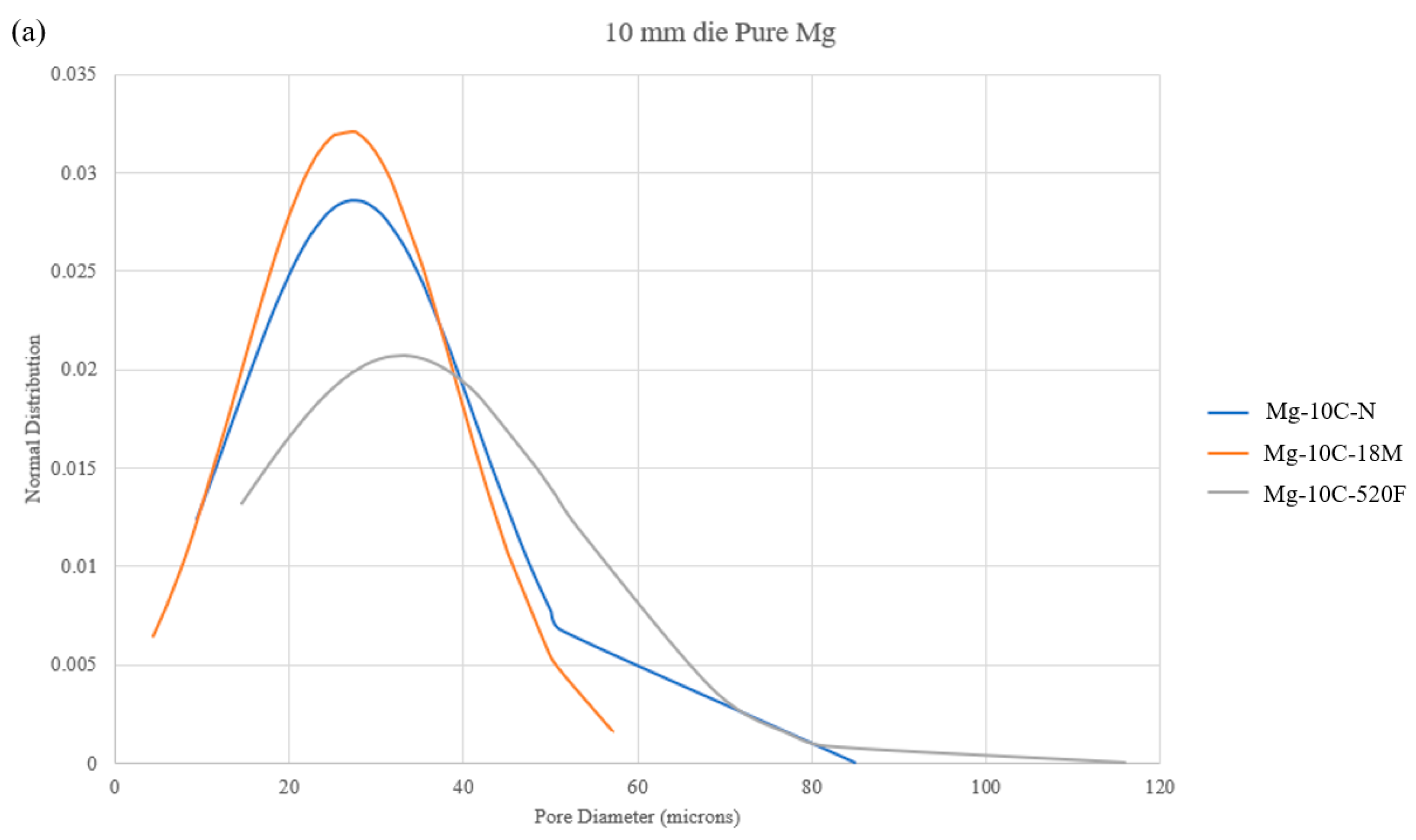
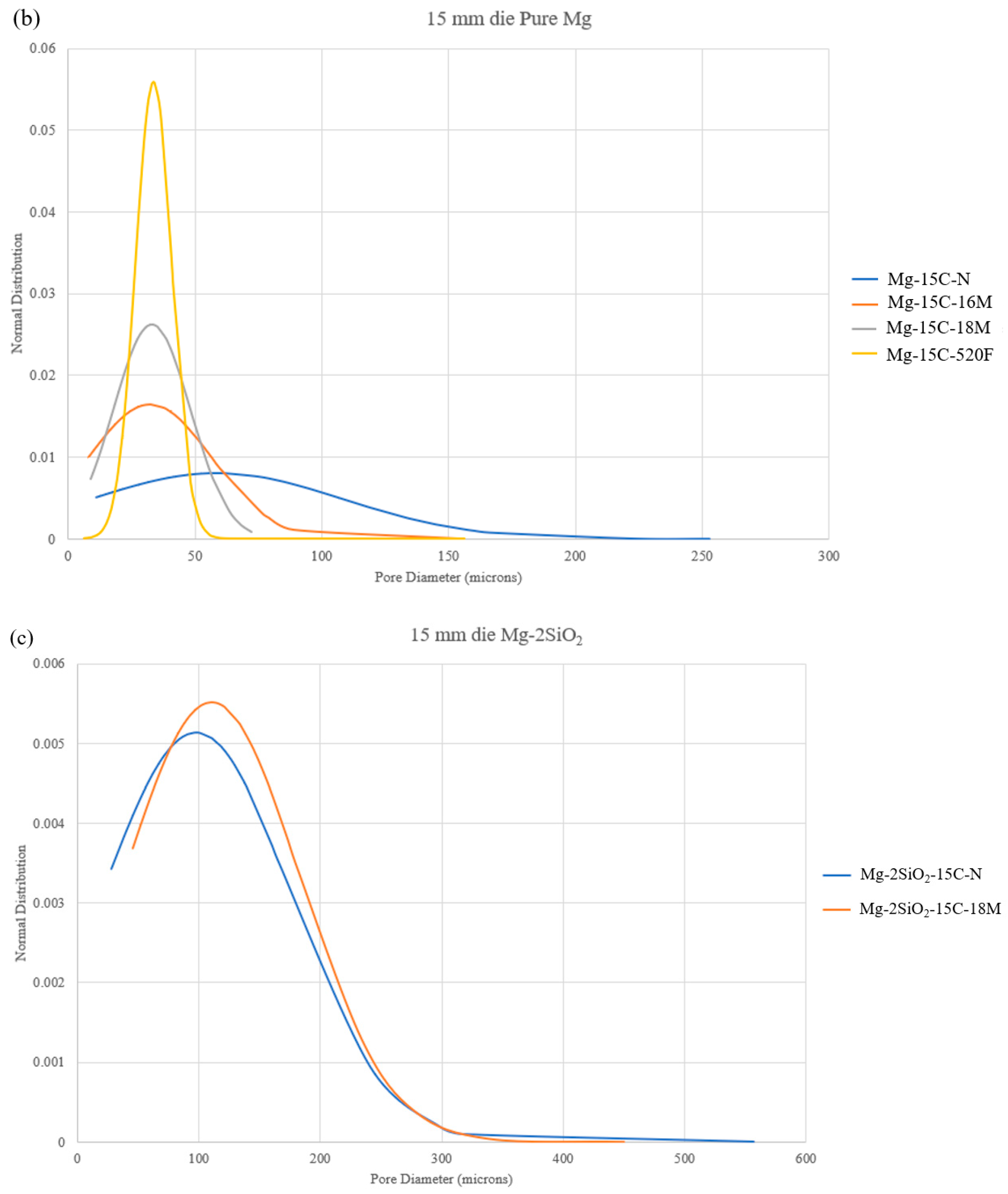
| Material | Average Pore Aspect Ratio | Average Pore Diameter (Microns) |
|---|---|---|
| Mg-15C-N | 4.6 ± 1.9 | 59 ± 50 |
| Mg-15C-16M | 3.9 ± 1.9 ↓ | 32 ± 24 ↓ |
| Mg-15C-18M | 6.5 ± 2.2 ↑ | 33 ± 15 ↓ |
| Mg-15C-520F | 7.3 ± 3.8 ↑ | 34 ± 7 ↓ |
| Mg-10C-N | 2.0 ± 0.8 | 27 ± 14 |
| Mg-10C-18M | 4.8 ± 2.4 ↑ | 27 ± 12 |
| Mg-10C-520F | 3.4 ± 1.1 ↑ | 33 ± 19 ↑ |
| Mg-2SiO2-15C-N | 5.1 ± 2.5 | 98 ± 78 |
| Mg-2SiO2-15C-18M | 6.5 ± 2.7 ↑ | 110 ± 72 ↑ |
| Material | Average Grain Diameter (Microns) |
|---|---|
| Mg-15C-N | 8 ± 2 |
| Mg-15C-16M | 25 ± 11 ↑ |
| Mg-15C-18M | 28 ± 10 ↑ |
| Mg-15C-520F | 21 ± 7 ↑ |
| Mg-10C-N | 6 ± 2 |
| Mg-10C-18M | 22 ± 7 ↑ |
| Mg-10C-520F | 22 ± 7 ↑ |
| Mg-2SiO2-15C-N | 5 ± 2 |
| Mg-2SiO2-15C-18M | 16 ± 5 ↑ |
| Mg-2SiO2 (extruded) [31] | 23 ± 2 |
| Material | Average Microhardness (Hv) |
|---|---|
| Mg-15C-N | 65 ± 5 |
| Mg-15C-16M | 61 ± 7 ↓ |
| Mg-15C-18M | 60 ± 8 ↓ |
| Mg-15C-520F | 65 ± 6 ↓ |
| Mg-10C-N | 74 ± 4 |
| Mg-10C-18M | 58 ± 6 ↓ |
| Mg-10C-520F | 62 ± 8 ↓ |
| Mg-2SiO2-15C-N | 83 ± 10 |
| Mg-2SiO2-15C-18M | 73 ± 9 ↓ |
| Mg-2SiO2 (extruded) [31] | 69 ± 2 |
| Material | Mean Young’s Modulus (GPa) | Mean 0.2% Yield Strength (MPa) | Mean Ultimate Compressive Strength (MPa) | Mean Fracture Strain (%) |
|---|---|---|---|---|
| Mg-15C-N | 1.27 ± 0.08 | 52.69 ± 6.39 | 87.56 ± 15.76 | 32.78 ± 4.68 |
| Mg-15C-16M | 1.20 ± 0.10 ↓ | 34.91 ± 3.69 ↓ | 73.39 ± 8.59 ↓ | 27.03 ± 2.93 ↓ |
| Mg-15C-18M | 1.09 ± 0.03 ↓ | 30.73 ± 0.90 ↓ | 76.31 ± 2.00 ↓ | 25.25 ± 0.89 ↓ |
| Mg-15C-520F | 1.06 ± 0.16 ↓ | 35.74 ± 6.75 ↓ | 78.87 ± 7.00 ↓ | 22.52 ± 3.11 ↓ |
| Mg-10C-N | 1.49 ± 0.21 | 63.67 ± 13.92 | 84.43 ± 20.15 | 27.3 ± 6.00 |
| Mg-10C-18M | 1.46 ± 0.12 ↓ | 47.62 ± 4.34 ↓ | 108.93 ± 5.28 ↑ | 22.7 ± 1.12 ↓ |
| Mg-10C-520F | 1.07 ± 0.36 ↓ | 38.79 ± 5.51 ↓ | 89.54 ± 11.29 ↑ | 26.15 ± 3.40 ↓ |
| Mg-2SiO2-15C-N | 1.04 ± 0.09 | 36.25 ± 6.28 | 41.02 ± 8.51 | 9.91 ± 1.49 |
| Mg-2SiO2-15C-18M | 1.05 ± 0.07 ↑ | 33.66 ± 4.47 ↓ | 43.68 ± 6.77 ↑ | 11.38 ± 1.65 ↑ |
| Cancellous bone [17,18,19,36,37] | 0.1–20 | - | 2–48 | - |
| Material | Average Porosity (%) | Mean Young’s Modulus (GPa) | Mean 0.2% Yield Strength (MPa) | Mean Ultimate Compressive Strength (MPa) | Mean Compressive Fracture Strain (%) |
|---|---|---|---|---|---|
| Mg-10C-18M (this study) | 3.26 | 1.46 ± 0.12 | 47.62 ± 4.34 | 108.93 ± 5.28 | 22.7 ± 1.12 |
| Mg-15C-18M (this study) | 12.85 | 1.09 ± 0.03 | 30.73 ± 0.90 | 76.31 ± 2.00 | 25.25 ± 0.89 |
| Mg-2SiO2-15C-18M (this study) | 13.94 | 1.05 ± 0.07 | 33.66 ± 4.47 | 43.68 ± 6.77 | 11.38 ± 1.65 |
| Porous Mg [12] | 30–55 | 1.45–2.21 | - | 63–103 | 6.4–7.1 |
| Porous Mg [13] | 62–75 | - | 0.5–20 | 4–14 | <5 |
| Porous Mg [14] | 29–31 | 0.6–1.2 | 13–53 | 20–70 | 5–17 |
| Porous Mg [15] | 50 | 0.35 | - | 6–7 | <5 |
| Cancellous bone [17,18,19,36,37,38,39] | 50–90 | 0.1–-20 | - | 2–48 | 1.11–4.0 |
Disclaimer/Publisher’s Note: The statements, opinions and data contained in all publications are solely those of the individual author(s) and contributor(s) and not of MDPI and/or the editor(s). MDPI and/or the editor(s) disclaim responsibility for any injury to people or property resulting from any ideas, methods, instructions or products referred to in the content. |
© 2023 by the authors. Licensee MDPI, Basel, Switzerland. This article is an open access article distributed under the terms and conditions of the Creative Commons Attribution (CC BY) license (https://creativecommons.org/licenses/by/4.0/).
Share and Cite
Johanes, M.; Gupta, M. An Investigation into the Potential of Turning Induced Deformation Technique for Developing Porous Magnesium and Mg-SiO2 Nanocomposite. Materials 2023, 16, 2463. https://doi.org/10.3390/ma16062463
Johanes M, Gupta M. An Investigation into the Potential of Turning Induced Deformation Technique for Developing Porous Magnesium and Mg-SiO2 Nanocomposite. Materials. 2023; 16(6):2463. https://doi.org/10.3390/ma16062463
Chicago/Turabian StyleJohanes, Michael, and Manoj Gupta. 2023. "An Investigation into the Potential of Turning Induced Deformation Technique for Developing Porous Magnesium and Mg-SiO2 Nanocomposite" Materials 16, no. 6: 2463. https://doi.org/10.3390/ma16062463