
Magnetic-Field-Assisted Molecular Beam Epitaxy: Engineering of Fe3O4 Ultrathin Films on MgO(111)
 , , and
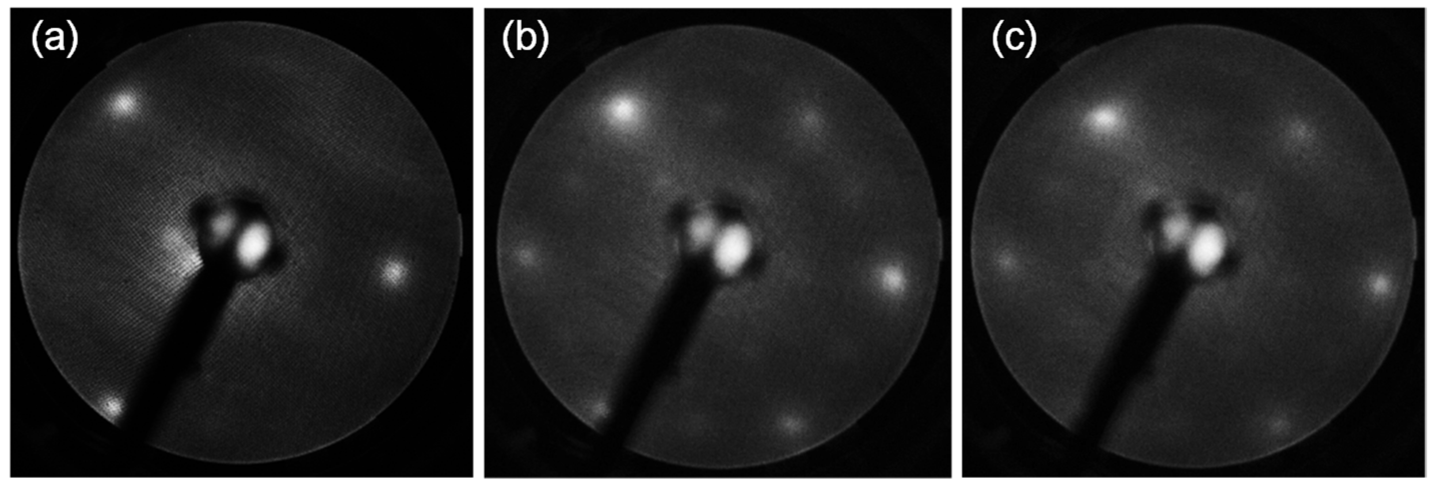
Abstract
:1. Introduction
2. Materials and Methods
2.1. Properties of Epitaxial Magnetite Films
2.2. Experimental Details
3. Results
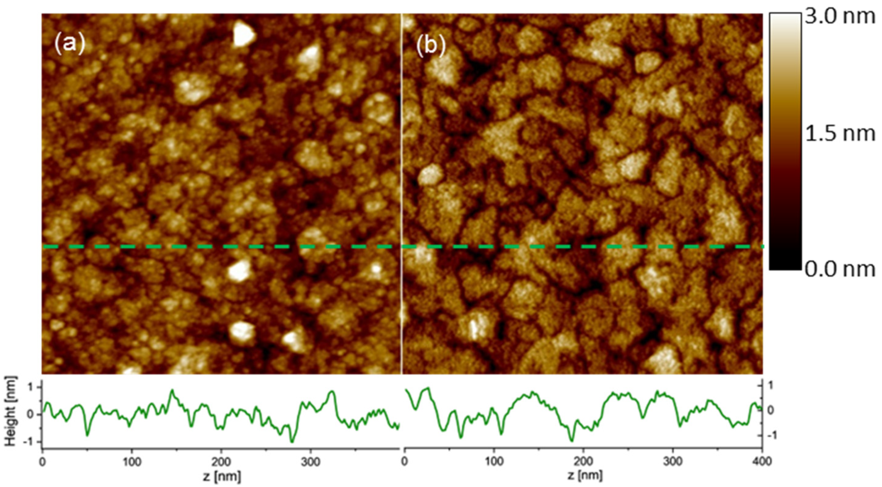
3.1. In Situ Characterization
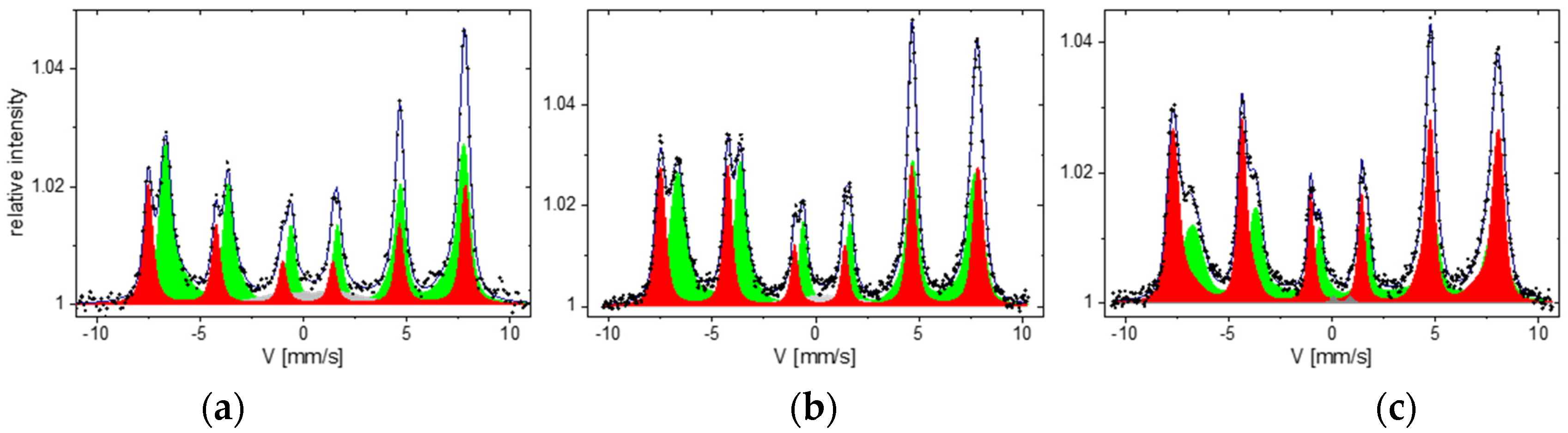
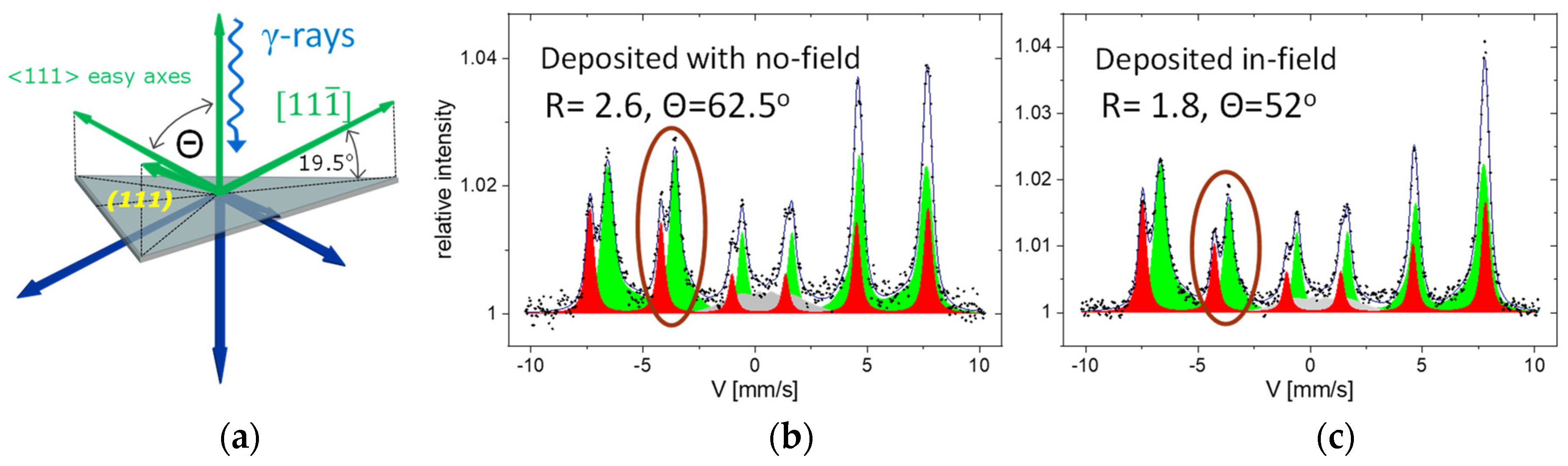
3.2. Magnetic Properties
4. Discussion and Conclusions
Supplementary Materials
Author Contributions
Funding
Institutional Review Board Statement
Informed Consent Statement
Data Availability Statement
Acknowledgments
Conflicts of Interest
References
- Krishnan, K.M.; Pakhomov, A.B.; Bao, Y.; Blomqvist, P.; Chun, Y.; Gonzales, M.; Griffin, K.; Ji, X.; Roberts, B.K. Nanomagnetism and spin electronics: Materials, microstructure and novel properties. J. Mater. Sci. 2006, 41, 793–815. [Google Scholar] [CrossRef]
- Zabel, H.; Bader, H.D. (Eds.) Magnetic Heterostructures, Advances and Perspectives in Spinstructures and Spintransport; Springer Tracts in Modern Physics; Springer: Berlin/Heidelberg, Germany, 2008; Volume 227. [Google Scholar] [CrossRef]
- Herman, M.A.; Sitter, H. Molecular Beam Epitaxy; Springer: Berlin/Heidelberg, Germany, 1996. [Google Scholar] [CrossRef]
- Kim, Y.; Gao, Y.; Chambers, S. Selective growth and characterization of pure, epitaxial α-Fe2O3(0001) and Fe3O4(001) films by plasma-assisted molecular beam epitaxy. Surf. Sci. 1997, 371, 358–370. [Google Scholar] [CrossRef]
- Kawaguchi, K.; Kita, R.; Nishiyama, M.; Morishita, T. Molecular beam epitaxy growth of CuO and Cu2O films with controlling the oxygen content by the flux ratio of Cu/O+. J. Cryst. Growth 1994, 143, 221–226. [Google Scholar] [CrossRef]
- Kumar, A.; Wetterskog, E.; Lewin, E.; Tai, C.-W.; Akansel, S.; Husain, S.; Edvinsson, T.; Brucas, R.; Chaudhary, S.; Svedlindh, P. Effect of in situ electric-field-assisted growth on antiphase boundaries in epitaxial Fe3O4 thin films on MgO. Phys. Rev. Mater. 2018, 2, 054407. [Google Scholar] [CrossRef]
- Kim, J.S.; Mohanty, B.C.; Han, C.S.; Han, S.J.; Ha, G.H.; Lin, L.; Cho, Y.S. In Situ Magnetic Field-Assisted Low Temperature Atmospheric Growth of GaN Nanowires via the Vapor–Liquid–Solid Mechanism. ACS Appl. Mater. Interfaces 2013, 6, 116–121. [Google Scholar] [CrossRef]
- Park, J.M.; Sohgawa, M.; Kanashima, T.; Okuyama, M.; Nakashima, S. Preparation of epitaxial BiFeO3 thin films on La-SrTiO3 substrate by using magnetic-field-assisted pulsed laser deposition. J. Korean Phys. Soc. 2013, 62, 1041–1045. [Google Scholar] [CrossRef]
- Nilsen, O.; Lie, M.; Foss, S.; Fjellvåg, H.; Kjekshus, A. Effect of magnetic field on the growth of α-Fe2O3 thin films by atomic layer deposition. Appl. Surf. Sci. 2004, 227, 40–47. [Google Scholar] [CrossRef]
- Zhang, K.; Dai, J.; Wu, W.; Zhang, P.; Zuo, X.; Zhou, S.; Zhu, X.; Sheng, Z.; Liang, C.; Sun, Y. Development of a high magnetic field assisted pulsed laser deposition system. Rev. Sci. Instrum. 2015, 86, 095105. [Google Scholar] [CrossRef]
- Stadler, D.; Mueller, D.N.; Brede, T.; Duchoň, T.; Fischer, T.; Sarkar, A.; Giesen, M.; Schneider, C.M.; Volkert, C.A.; Mathur, S. Magnetic Field-Assisted Chemical Vapor Deposition of Iron Oxide Thin Films: Influence of Field–Matter Interactions on Phase Composition and Morphology. J. Phys. Chem. Lett. 2019, 10, 6253–6259. [Google Scholar] [CrossRef]
- Ikeda, S.; Miura, K.; Yamamoto, H.; Mizunuma, K.; Gan, H.D.; Endo, M.; Kanai, S.; Hayakawa, J.; Matsukura, F.; Ohno, H. A perpendicular-anisotropy CoFeB–MgO magnetic tunnel junction. Nat. Mater. 2010, 9, 721–724. [Google Scholar] [CrossRef]
- Moussy, J.-B. From epitaxial growth of ferrite thin films to spin-polarized tunnelling. J. Phys. D Appl. Phys. 2013, 46. [Google Scholar] [CrossRef]
- Walz, F. The Verwey transition—A topical review. J. Phys. Condens. Matter. 2002, 14, R285–R340. [Google Scholar] [CrossRef]
- Ka̧kol, Z.; Honig, J.M. Influence of deviations from ideal stoichiometry on the anisotropy parameters of magnetite Fe3(1−δ)O4. Phys. Rev. B 1989, 40, 9090–9097. [Google Scholar] [CrossRef] [PubMed]
- Banerjee, S.K.; Moskowitz, B.M. Ferrimagnetic Properties of Magnetite. In Magnetite Biomineralization and Magnetoreception in Organisms; Topics in Geobiology; Kirschvink, J.L., Jones, D.S., MacFadden, B.J., Eds.; Springer: Boston, MA, USA, 1985; Volume 5, pp. 17–41. [Google Scholar] [CrossRef]
- Weiss, W.; Barbieri, A.; Van Hove, M.A.; Somorjai, G.A. Surface structure determination of an oxide film grown on a foreign substrate:Fe3O4 multilayer on Pt(111) identified by low energy electron diffraction. Phys. Rev. Lett. 1993, 71, 1848–1851. [Google Scholar] [CrossRef] [PubMed]
- Michalak, N.; Miłosz, Z.; Peschel, G.; Prieto, M.; Xiong, F.; Wojciechowski, P.; Schmidt, T.; Lewandowski, M. Symmetry-Induced Structuring of Ultrathin FeO and Fe3O4 Films on Pt(111) and Ru(0001). Nanomaterials 2018, 8, 719. [Google Scholar] [CrossRef] [PubMed]
- Spiridis, N.; Barbasz, J.; Łodziana, Z.; Korecki, J. Fe3O4(001) films on Fe(001): Termination and reconstruction of iron-rich surfaces. Phys. Rev. B 2006, 74, 155423. [Google Scholar] [CrossRef]
- Fujii, T.; Takano, M.; Katano, R.; Bando, Y.; Isozumi, Y. Preparation and characterization of (111)-oriented Fe3O4 films deposited on sapphire. J. Appl. Phys. 1989, 66, 3168–3172. [Google Scholar] [CrossRef]
- Margulies, D.T.; Parker, F.T.; Spada, F.E.; Goldman, R.S.; Li, J.; Sinclair, R.; Berkowitz, A.E. Anomalous moment and anisotropy behavior in Fe3O4 films. Phys. Rev. B 1996, 53, 9175–9187. [Google Scholar] [CrossRef]
- Bataille, A.M.; Ponson, L.; Gota, S.; Barbier, L.; Bonamy, D.; Gautier-Soyer, M.; Gatel, C.; Snoeck, E. Characterization of antiphase boundary network in Fe3O4(111) epitaxial thin films: Effect on anomalous magnetic behavior. Phys. Rev. B 2006, 74. [Google Scholar] [CrossRef]
- Kallmayer, M.; Hild, K.; Elmers, H.J.; Arora, S.K.; Wu, H.-C.; Sofin, R.G.S.; Shvets, I.V. Magnetic moment investigations of epitaxial magnetite thin films. J. Appl. Phys. 2008, 103, 07D715. [Google Scholar] [CrossRef]
- Cuñado, J.L.F.; Camarero, J.; Pedrosa, F.J.; Nemes, N.M.; Sanz, M.; Oujja, M.; Rebollar, E.; Marco, J.F.; de la Figuera, J.; Monti, M.; et al. Evidence of anomalous switching of the in-plane magnetic easy axis with temperature in Fe3O4 film on SrTiO3:Nb by v-MOKE and ferromagnetic resonance. Nanoscale 2019, 11, 19870–19876. [Google Scholar] [CrossRef] [PubMed]
- Fujii, T.; Takano, M.; Katano, R.; Bando, Y.; Isozumi, Y. CEMS study of the growth and properties of Fe3O4 films. J. Cryst. Growth 1990, 99, 606–610. [Google Scholar] [CrossRef]
- Margulies, D.T.; Parker, F.T.; Berkowitz, A.E. Magnetic anomalies in single crystal Fe3O4 thin films. J. Appl. Phys. 1994, 75, 6097–6099. [Google Scholar] [CrossRef]
- van der Heijden, P.; Bloemen, P.; Gaines, J.; van Eemeren, J.; Wolf, R.; van der Zaag, P.; de Jonge, W. Magnetic interface anisotropy of MBE-grown ultra-thin (001) Fe3O4 layers. J. Magn. Magn. Mater. 1996, 159, L293–L298. [Google Scholar] [CrossRef]
- Fontijn, W.; Van Der Heijden, P.; Voogt, F.; Hibma, T.; Van Der Zaag, P. Comparison of a stoichiometric analysis of Fe3−δO4 layers by magneto-optical Kerr spectroscopy with Mössbauer results. J. Magn. Magn. Mater. 1997, 165, 401–404. [Google Scholar] [CrossRef]
- Gong, G.Q.; Gupta, A.; Xiao, G.; Qian, W.; Dravid, V.P. Magnetoresistance and magnetic properties of epitaxial magnetite thin films. Phys. Rev. B 1997, 56, 5096–5099. [Google Scholar] [CrossRef]
- Ruby, C.; Fusy, J.; Génin, J.-M. Preparation and characterisation of iron oxide films deposited on MgO(100). Thin Solid Film. 1999, 352, 22–28. [Google Scholar] [CrossRef]
- Li, X.W.; Gupta, A.; Xiao, G.; Gong, G.Q. Transport and magnetic properties of epitaxial and polycrystalline magnetite thin films. J. Appl. Phys. 1998, 83, 7049–7051. [Google Scholar] [CrossRef]
- Sena, S.; Lindley, R.; Blythe, H.; Sauer, C.; Al-Kafarji, M.; Gehring, G. Investigation of magnetite thin films produced by pulsed laser deposition. J. Magn. Magn. Mater. 1997, 176, 111–126. [Google Scholar] [CrossRef]
- Voogt, F.C.; Palstra, T.T.M.; Niesen, L.; Rogojanu, O.C.; James, M.A.; Hibma, T. Superparamagnetic behavior of structural domains in epitaxial ultrathin magnetite films. Phys. Rev. B 1998, 57, R8107–R8110. [Google Scholar] [CrossRef]
- Margulies, D.T.; Parker, F.T.; Rudee, M.L.; Spada, F.E.; Chapman, J.N.; Aitchison, P.R.; Berkowitz, A.E. Origin of the Anomalous Magnetic Behavior in Single Crystal Fe3O4 Films. Phys. Rev. Lett. 1997, 79, 5162–5165. [Google Scholar] [CrossRef]
- Lee, A.K.H.; Jayathilaka, P.B.; Bauer, C.A.; Monti, M.C.; Markert, J.T.; De Lozanne, A.; Miller, C.W. Magnetic force microscopy of epitaxial magnetite films through the Verwey transition. Appl. Phys. Lett. 2010, 97, 162502. [Google Scholar] [CrossRef]
- Kale, S.; Bhagat, S.M.; Lofland, S.E.; Scabarozi, T.; Ogale, S.B.; Orozco, A.; Shinde, S.R.; Venkatesan, T.; Hannoyer, B.; Mercey, B.; et al. Film thickness and temperature dependence of the magnetic properties of pulsed-laser-deposited Fe3O4 films on different substrates. Phys. Rev. B 2001, 64, 205413. [Google Scholar] [CrossRef]
- Morrall, P.; Schedin, F.; Langridge, S.; Bland, J.; Thomas, M.F.; Thornton, G. Magnetic moment in an ultrathin magnetite film. J. Appl. Phys. 2003, 93, 7960–7962. [Google Scholar] [CrossRef]
- Arora, S.K.; Wu, H.-C.; Choudhary, R.J.; Shvets, I.V.; Mryasov, O.N.; Yao, H.; Ching, W.Y. Giant magnetic moment in epitaxial Fe3O4 thin films on MgO(100). Phys. Rev. B 2008, 77, 134443. [Google Scholar] [CrossRef]
- Orna, J.; Algarabel, P.A.; Morellón, L.; Pardo, J.A.; de Teresa, J.M.; Antón, R.L.; Bartolomé, F.; García, L.M.; Cezar, J.C.; Wildes, A. Origin of the giant magnetic moment in epitaxial Fe3O4 thin films. Phys. Rev. B 2010, 81. [Google Scholar] [CrossRef]
- Zhang, J.; Liu, W.; Zhang, M.; Zhang, X.; Niu, W.; Gao, M.; Wang, X.; Du, J.; Zhang, R.; Xu, Y. Oxygen pressure-tuned epitaxy and magnetic properties of magnetite thin films. J. Magn. Magn. Mater. 2017, 432, 472–476. [Google Scholar] [CrossRef]
- Monti, M.; Sanz, M.; Oujja, M.; Rebollar, E.; Castillejo, M.; Pedrosa, F.J.; Bollero, A.; Camarero, J.; Cuñado, J.L.F.; Nemes, N.M.; et al. Room temperature in-plane ⟨100⟩ magnetic easy axis for Fe3O4/SrTiO3(001):Nb grown by infrared pulsed laser deposition. J. Appl. Phys. 2013, 114, 223902. [Google Scholar] [CrossRef]
- Voogt, F.C.; Fujii, T.; Smulders, P.J.M.; Niesen, L.; James, M.A.; Hibma, T. NO2-assisted molecular-beam epitaxy of Fe3O4, Fe3−δO4, and γ−Fe2O3 thin films on MgO(100). Phys. Rev. B 1999, 60, 11193–11206. [Google Scholar] [CrossRef]
- Zając, M.; Freindl, K.; Ślęzak, T.; Ślęzak, M.; Spiridis, N.; Wilgocka-Ślęzak, D.; Korecki, J. Electronic and magnetic properties of ultra-thin epitaxial magnetite films on MgO(001). Thin Solid Film. 2011, 519, 5588–5595. [Google Scholar] [CrossRef]
- Kaji, E.; Subagyo, A.; Arita, M.; Sueoka, K. Surface magnetic structure of epitaxial magnetite thin films grown on MgO(001). J. Appl. Phys. 2009, 105, 07D545. [Google Scholar] [CrossRef]
- Kalev, L.A.; Niesen, L. Nuclear resonance scattering study on the spin orientation in an epitaxial layer of Fe3O4 on MgO(100). Phys. Rev. B 2003, 67, 224403. [Google Scholar] [CrossRef]
- Schedin, F.; Hewitt, L.; Morrall, P.; Petrov, V.N.; Thornton, G.; Case, S.; Thomas, M.F.; Uzdin, V.M. In-plane magnetization of an ultrathin film of Fe3O4(111) grown epitaxially on Pt(111). Phys. Rev. B 1998, 58, R11861–R11863. [Google Scholar] [CrossRef]
- Spiridis, N.; Freindl, K.; Wojas, J.; Kwiatek, N.; Madej, E.; Wilgocka-Ślęzak, D.; Dróżdż, P.; Ślęzak, T.; Korecki, J. Superstructures on Epitaxial Fe3O4(111) Films: Biphase Formation versus the Degree of Reduction. J. Phys. Chem. C 2019, 123, 4204–4216. [Google Scholar] [CrossRef]
- Lewandowski, M.; Miłosz, Z.; Michalak, N.; Ranecki, R.; Sveklo, I.; Kurant, Z.; Maziewski, A.; Mielcarek, S.; Luciński, T.; Jurga, S. Room temperature magnetism of few-nanometers-thick Fe3O4(111) films on Pt(111) and Ru(0001) studied in ambient conditions. Thin Solid Film. 2015, 591, 285–288. [Google Scholar] [CrossRef]
- Pohl, A.; Berger, F.; Sullan, R.M.A.; Valverde-Tercedor, C.; Freindl, K.; Spiridis, N.; Lefèvre, C.T.; Menguy, N.; Klumpp, S.; Blank, K.G.; et al. Decoding Biomineralization: Interaction of a Mad10-Derived Peptide with Magnetite Thin Films. Nano Lett. 2019, 19, 8207–8215. [Google Scholar] [CrossRef]
- Lazarov, V.K.; Weinert, M.; Chambers, S.; Gajdardziska-Josifovska, M. Atomic and electronic structure of the Fe3O4(111)/MgO(111) model polar oxide interface. Phys. Rev. B-Condens. Matter Mater. Phys. 2005, 72, 1–7. [Google Scholar] [CrossRef]
- Chichvarina, O.; Herng, T.S.; Xiao, W.; Hong, X.; Ding, J. Magnetic anisotropy modulation of epitaxial Fe3O4 films on MgO substrates. J. Appl. Phys. 2015, 117, 17D722. [Google Scholar] [CrossRef]
- Available online: https://www.prevac.eu/en/2,offer/36,sample-holders/339,flag-style-sample-holders.html (accessed on 11 January 2023).
- Available online: http://www.w-musial.home.pl/ang/index.htm (accessed on 11 January 2023).
- Rancourt, D.; Ping, J. Voigt-based methods for arbitrary-shape static hyperfine parameter distributions in Mössbauer spectroscopy. Nucl. Instrum. Methods Phys. Res. Sect. B Beam Interact. Mater. At. 1991, 58, 85–97. [Google Scholar] [CrossRef]
- Lazarov, V.K.; Plass, R.; Poon, H.-C.; Saldin, D.K.; Weinert, M.; Chambers, S.A.; Gajdardziska-Josifovska, M. Structure of the hydrogen-stabilizedMgO(111)-(1×1)polar surface: Integrated experimental and theoretical studies. Phys. Rev. B 2005, 71, 115434. [Google Scholar] [CrossRef]
- Freindl, K.; Wojas, J.; Kwiatek, N.; Korecki, J.; Spiridis, N. Reversible oxidation–reduction of epitaxial iron oxide films on Pt(111): Magnetite–hematite interconversion. J. Chem. Phys. 2020, 152, 054701. [Google Scholar] [CrossRef] [PubMed]
- Sawatzky, G.A.; Van Der Woude, F.; Morrish, A.H. Recoilless-Fraction Ratios for Fe57 in Octahedral and Tetrahedral Sites of a Spinel and a Garnet. Phys. Rev. 1969, 183, 383–386. [Google Scholar] [CrossRef]
- Vandenberghe, R.; Barrero, C.; Da Costa, G.; Van San, E.; De Grave, E. Mössbauer characterization of iron oxides and (oxy)hydroxides: The present state of the art. Hyperfine Interact. 2000, 126, 247–259. [Google Scholar] [CrossRef]
- Chlan, V.; Żukrowski, J.; Bosak, A.; Kąkol, Z.; Kozłowski, A.; Tarnawski, Z.; Řezníček, R.; Štěpánková, H.; Novák, P.; Biało, I.; et al. Effect of low Zn doping on the Verwey transition in magnetite single crystals: Mössbauer spectroscopy and x-ray diffraction. Phys. Rev. B 2018, 98, 125138. [Google Scholar] [CrossRef]
- Korecki, J.; Gradmann, U. In Situ Mössbauer Analysis of Hyperfine Interactions near Fe(110) Surfaces and Interfaces. Phys. Rev. Lett. 1985, 55, 2491–2494. [Google Scholar] [CrossRef]
- Ding, H.; Pütter, S.; Oepen, H.; Kirschner, J. Experimental method for separating longitudinal and polar Kerr signals. J. Magn. Magn. Mater. 2000, 212, 5–11. [Google Scholar] [CrossRef]
- Sander, D.; Ouazi, S.; Enders, A.; Gutjahr-Löser, T.; Stepanyuk, V.S.; I Bazhanov, D.; Kirschner, J. Stress, strain and magnetostriction in epitaxial films. J. Phys. Condens. Matter 2002, 14, 4165–4176. [Google Scholar] [CrossRef]
- Brandlmaier, A.; Geprägs, S.; Weiler, M.; Boger, A.; Opel, M.; Huebl, H.; Bihler, C.; Brandt, M.S.; Botters, B.; Grundler, D.; et al. In situ manipulation of magnetic anisotropy in magnetite thin films. Phys. Rev. B 2008, 77, 104445. [Google Scholar] [CrossRef]


Disclaimer/Publisher’s Note: The statements, opinions and data contained in all publications are solely those of the individual author(s) and contributor(s) and not of MDPI and/or the editor(s). MDPI and/or the editor(s) disclaim responsibility for any injury to people or property resulting from any ideas, methods, instructions or products referred to in the content. |
© 2023 by the authors. Licensee MDPI, Basel, Switzerland. This article is an open access article distributed under the terms and conditions of the Creative Commons Attribution (CC BY) license (https://creativecommons.org/licenses/by/4.0/).
Share and Cite
Dziwoki, A.; Blyzniuk, B.; Freindl, K.; Madej, E.; Młyńczak, E.; Wilgocka-Ślęzak, D.; Korecki, J.; Spiridis, N. Magnetic-Field-Assisted Molecular Beam Epitaxy: Engineering of Fe3O4 Ultrathin Films on MgO(111). Materials 2023, 16, 1485. https://doi.org/10.3390/ma16041485
Dziwoki A, Blyzniuk B, Freindl K, Madej E, Młyńczak E, Wilgocka-Ślęzak D, Korecki J, Spiridis N. Magnetic-Field-Assisted Molecular Beam Epitaxy: Engineering of Fe3O4 Ultrathin Films on MgO(111). Materials. 2023; 16(4):1485. https://doi.org/10.3390/ma16041485
Chicago/Turabian StyleDziwoki, Adam, Bohdana Blyzniuk, Kinga Freindl, Ewa Madej, Ewa Młyńczak, Dorota Wilgocka-Ślęzak, Józef Korecki, and Nika Spiridis. 2023. "Magnetic-Field-Assisted Molecular Beam Epitaxy: Engineering of Fe3O4 Ultrathin Films on MgO(111)" Materials 16, no. 4: 1485. https://doi.org/10.3390/ma16041485