
The Structure and Properties of Laser-Cladded Inconel 625/TiC Composite Coatings


Abstract
:1. Introduction
2. Materials and Methods
2.1. Materials and Laser Processing
2.2. Penetrant Tests and Macroscopic Investigation
2.3. Microstructure Investigation and Hardness Testing
3. Results and Discussion
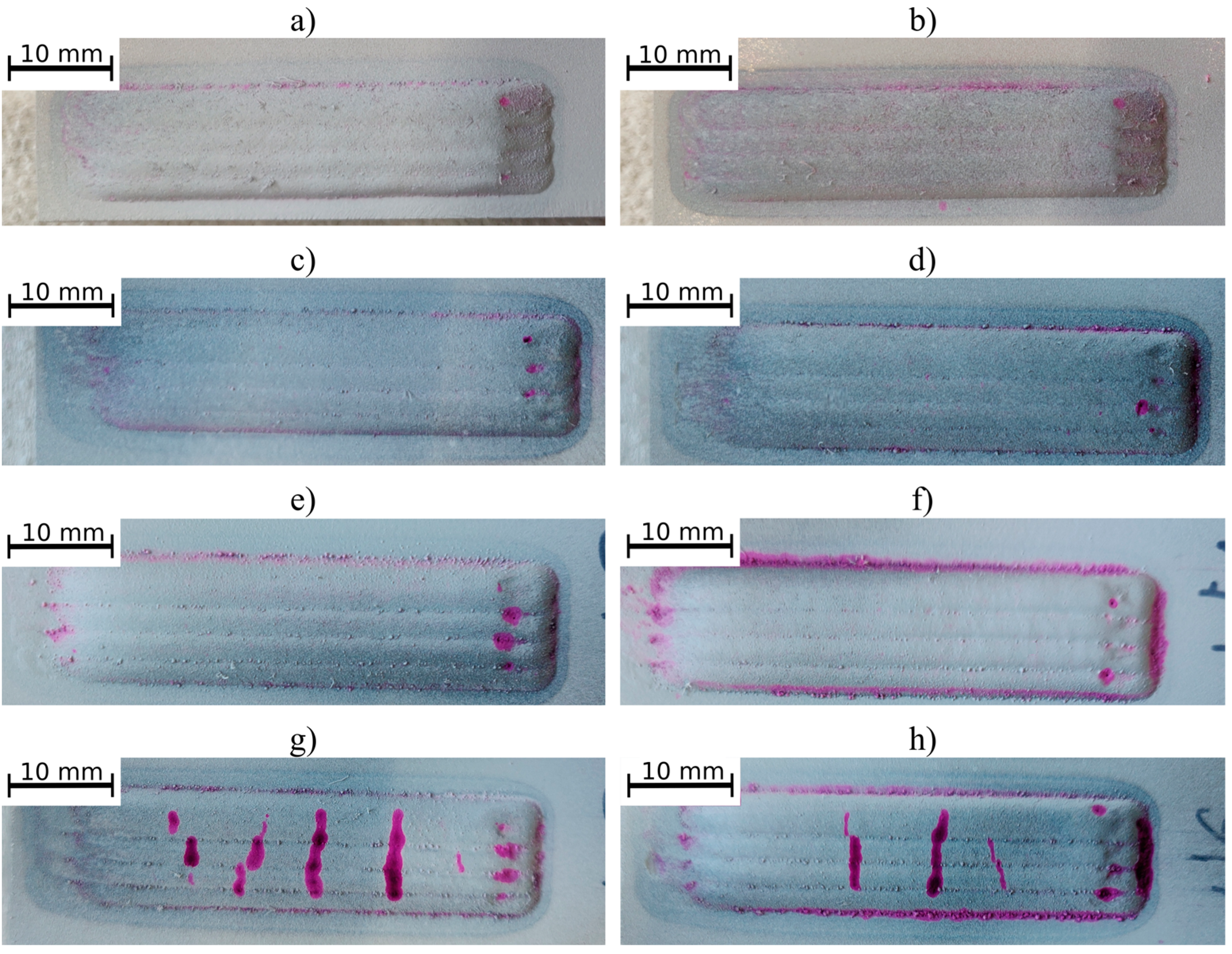
3.1. Penetrant Tests
3.2. Macrostructure
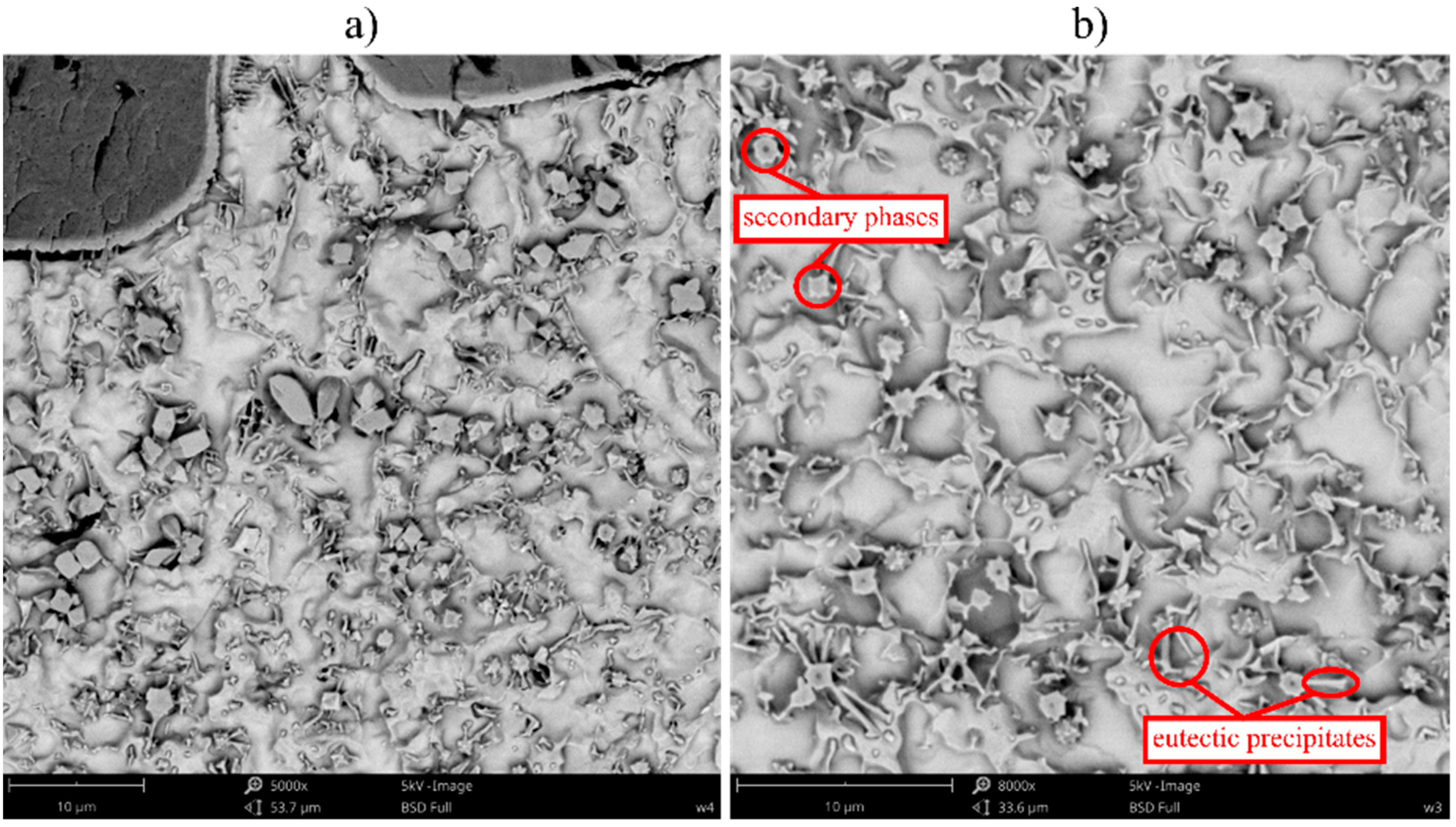
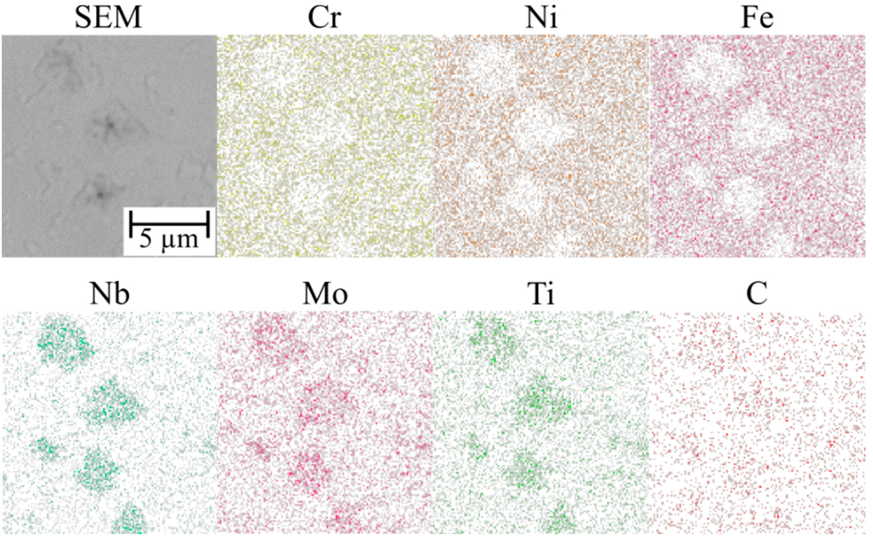
3.3. Microstructure
3.4. Hardness
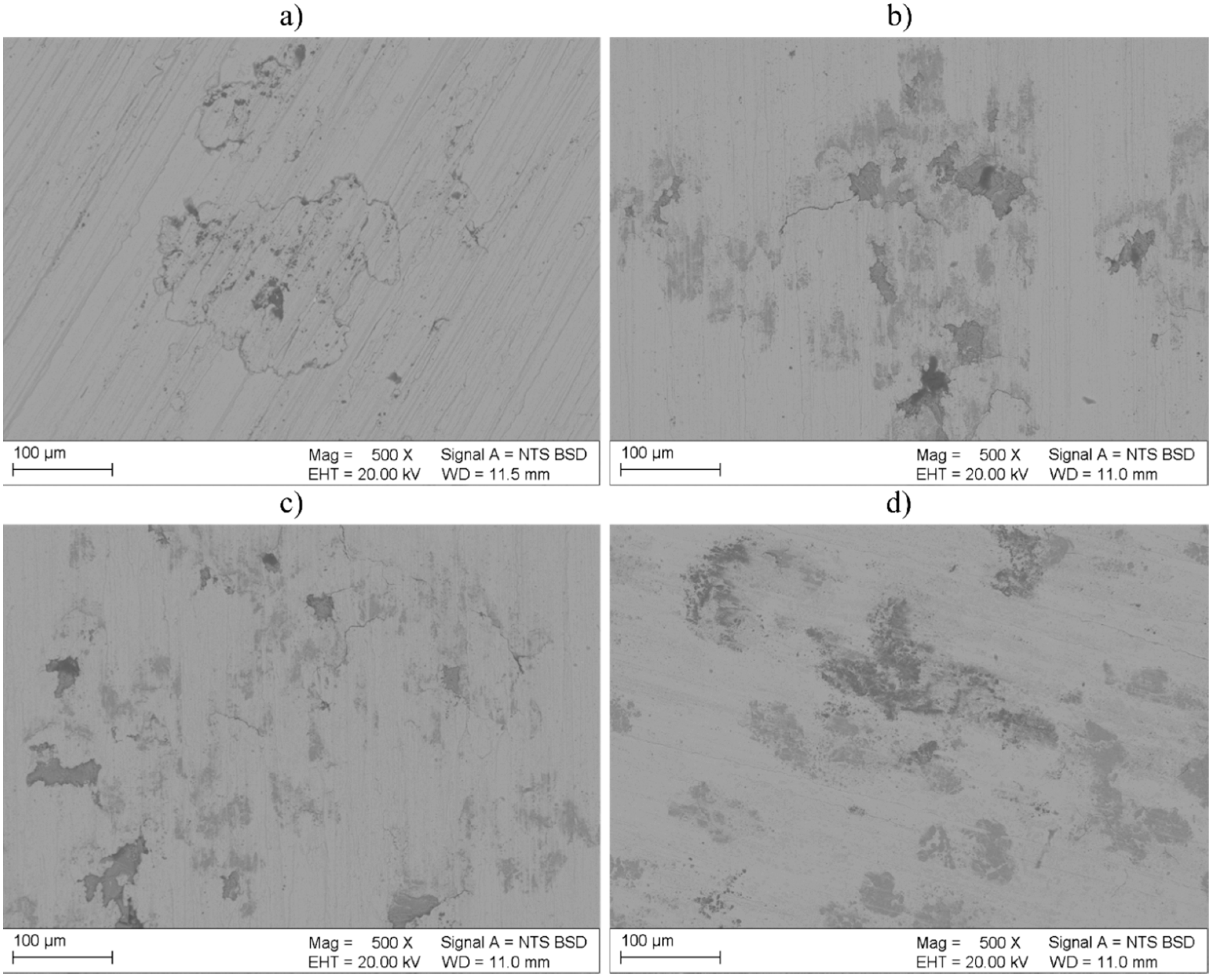
3.5. Corrosion Behavior
4. Conclusions
- The process of laser cladding can be used for the fabrication of homogeneous Inconel 625-based ex situ composite coatings containing up to 40 vol.% of TiC particles. The parameters of the powder feed rate, constant laser beam power and cladding rate influenced the penetration and dilution of coatings; however, it had no significant influence on their homogeneity.
- During the laser-cladding process, the TiC particles partially dissolved in the liquid pool, thus causing enrichment of the matrix with carbon and titanium. The crystallization process was accompanied by the precipitation of minor blocky secondary phases rich in carbon, titanium, niobium and molybdenum. The dissolution of TiC particles was more intense in the overlap area and triggered the additional formation of dendritic precipitates rich in carbon, titanium, niobium and molybdenum.
- The average microhardness of the composite Inconel 625/TiC coatings was higher than that of the metallic Inconel 625 coatings and was restricted within the range of 258 HV0.2 to 342 HV0.2. The average microhardness of the coatings increased along with an increase in the TiC content. The increase in coating dilution, accompanied by a decrease in the powder feed rate resulted in a decrease in average microhardness. In the overlap areas, no significant or repeated microhardness changes were noticed.
- The Inconel 625 coating was characterized by high corrosion resistance in a 3.5% NaCl solution. The corrosion resistance of the composite TiC-reinforced coatings was lower than that of the metallic coating.
Author Contributions
Funding
Institutional Review Board Statement
Informed Consent Statement
Data Availability Statement
Conflicts of Interest
References
- Mehta, J.; Mittal, V.K.; Gupta, P. Role of Thermal Spray Coatings on Wear, Erosion and Corrosion Behavior: A Review. J. Appl. Eng. 2017, 20, 445–452. [Google Scholar]
- Lisiecki, A. Tribology and surface engineering. Coatings 2019, 9, 663. [Google Scholar] [CrossRef]
- Ostovan, F.; Hasanzadeh, E.; Toozanehjani, M.; Shafiei, E.; Jamaluddin, K.R.; Amrin, A. Inconel 625 Super Alloy over A517 Carbon Steel Using ERNiCrMo3 Filler Metal. J. Mater. Eng. Perform 2020, 29, 6919–6930. [Google Scholar] [CrossRef]
- Jamrozik, W.; Górka, J.; Wyględacz, B.; Kiel-Jamrozik, M. FEM-based thermogram correction for Inconel 625 joint hardness clustering. Materials 2022, 15, 1113. [Google Scholar] [CrossRef]
- Scendo, M.; Staszewska-Samson, K.; Danielewski, H. Corrosion Behavior of Inconel 625 Coating Produced by Laser Cladding. Coatings 2021, 11, 759. [Google Scholar] [CrossRef]
- Czupryński, A.; Żuk, M. Matrix composite coatings deposited on AISI 4715 steel by powder plasma-transferred arc welding. Materials 2021, 14, 6066. [Google Scholar] [CrossRef] [PubMed]
- Lont, A.; Górka, J.; Janicki, D.; Matus, K. The Laser Alloying Process of Ductile Cast Iron Surface with Titanium Powder in Nitrogen Atmosphere. Coatings 2021, 12, 227. [Google Scholar] [CrossRef]
- Abioye, T.E.; McCartney, D.G.; Clare, A.T. Laser cladding of Inconel 625 wire for corrosion protection. J. Mater. Process. Technol. 2015, 217, 232–240. [Google Scholar] [CrossRef]
- Janicki, D.; Musztyfaga-Staszuk, M. Direct diode laser cladding of Inconel 625/WC composite coatings. Stroj. Vestn./J. Mech. Eng. 2016, 62, 363–372. [Google Scholar] [CrossRef]
- Janicki, D. Laser cladding of Inconel 625-based composite coatings reinforced by porous chromium carbide particles. Opt. Laser Technol. 2017, 94, 6–14. [Google Scholar] [CrossRef]
- Nurminen, J.; Nakki, J.; Vuoristo, P. Microstructure and properties of hard and wear resistant MMC coatings deposited by laser cladding. Int. J. Refract Hard Met. 2009, 27, 472–478. [Google Scholar] [CrossRef]
- Xu, X.; Mi, G.; Xiong, L.; Jiang, P.; Shao, X.; Wang, C. Morphologies, microstructures and properties of TiC particle reinforced Inconel 625 coatings obtained by laser cladding with wire. J. Alloy. Compd. 2018, 740, 16–27. [Google Scholar] [CrossRef]
- Kim, S.H.; Shin, G.H.; Kim, B.K.; Kim, K.T.; Yang, D.Y.; Aranas, C.; Choi, J.P.; Yu, J.H. Thermo-mechanical improvement of Inconel 718 using ex situ boron nitride-reinforced composites processed by laser powder bed fusion. Sci. Rep. 2017, 7, 14359. [Google Scholar] [CrossRef]
- Shivalingaiah, K.; Sridhar, K.S.; Sethuram, D.; Shivananda Murthy, K.V.; Koppad, P.G.; Ramesh, C.S. HVOF sprayed Inconel 718/cubic boron nitride composite coatings: Microstructure, microhardness and slurry erosive behaviour. Mater. Res. Express 2019, 6, 1265i8. [Google Scholar] [CrossRef]
- Tang, B.; Tan, Y.; Zhang, Z.; Xu, T.; Sun, Z.; Li, X. Effects of process parameters on geometrical characteristics, microstructure and tribological properties of TiB2 reinforced Inconel 718 alloy composite coatings by laser cladding. Coatings 2020, 10, 76. [Google Scholar] [CrossRef]
- Zhou, S.; Xu, T.; Hu, C.; Wu, H.; Liu, H.; Ma, X. A comparative study of tungsten carbide and carbon nanotubes reinforced Inconel 625 composite coatings fabricated by laser cladding. Opt. Laser Technol. 2021, 140, 106967. [Google Scholar] [CrossRef]
- Deng, P.; Yao, C.; Feng, K.; Huang, X.; Li, Z.; Li, Y.; Zhao, H. Enhanced wear resistance of laser cladded graphene nanoplatelets reinforced Inconel 625 superalloy composite coating. Surf. Coat. Technol. 2018, 335, 334–344. [Google Scholar] [CrossRef]
- Kotarska, A.; Poloczek, T.; Janicki, D. Characterization of the Structure, Mechanical Properties and Erosive Resistance of the Laser Cladded Inconel 625-Based Coatings Reinforced by TiC Particles. Materials 2021, 14, 2225. [Google Scholar] [CrossRef]
- Galevsky, G.V.; Rudneva, V.V.; Garbuzova, A.K.; Valuev, D.V. Titanium Carbide: Nanotechnology, Properties, Application. IOP Conf. Ser. Mater. Sci. Eng. 2015, 91, 012017. [Google Scholar] [CrossRef]
- Gopinath, M.; Mullick, S.; Nath, A.K. Development of process maps based on molten pool thermal history during laser cladding of Inconel 718/TiC metal matrix composite coatings. Surf. Coat. Technol. 2020, 399, 126100. [Google Scholar]
- Cao, S.; Gu, D. Laser metal deposition additive manufacturing of TiC/Inconel 625 nanocomposites: Relation of densification, microstructures and performance. J. Mater. Res. 2015, 30, 3616–3628. [Google Scholar] [CrossRef]
- Jiang, D.; Hong, C.; Zhong, M.; Alkhayat, M.; Weisheit, A.; Gasser, A.; Zhang, H.; Kelbassa, I.; Poprawe, R. Fabrication of nano-TiCp reinforced Inconel 625 composite coatings by partial dissolution of micro-TiCp through laser cladding energy input control. Surf. Coat. Technol. 2014, 249, 125–131. [Google Scholar] [CrossRef]
- Lian, G.; Zhang, H.; Zhang, Y.; Yao, M.; Huang, X.; Chen, C. Computational and Experimental Investigation of Micro-Hardness and Wear Resistance of Ni-Based Alloy and TiC Composite Coating Obtained by Laser Cladding. Materials 2019, 12, 793. [Google Scholar] [CrossRef] [PubMed]
- Ge, T.; Chen, L.; Gu, P.; Ren, X.; Chen, X. Microstructure and corrosion resistance of TiC/Inconel 625 composite coatings by extreme high speed laser cladding. Opt. Laser Technol. 2022, 150, 107919. [Google Scholar] [CrossRef]
- Bakkar, A.; Ahmed, M.M.Z.; Alsaleh, N.A.; El-Sayed Seleman, M.M.; Ataya, S. Microstructure, wear, and corrosion characterization of high TiC content Inconel 625 matrix composites. J. Mater. Res. Technol. 2019, 8, 1102–1110. [Google Scholar] [CrossRef]
- Poloczek, T.; Janicki, D.; Górka, J.; Kotarska, A. Effect of Ti and C alloyants on the microstructure of laser cladded cobalt-chromium coatings. IOP Conf. Ser. Mater. Sci. Eng. 2021, 1182, 012063. [Google Scholar] [CrossRef]
- Janicki, D. Shaping the Structure and Properties of Surface Layers of Ductile Cast Iron by Laser Alloying, 1st ed.; Publishing House of the Silesian University of Technology: Gliwice, Poland, 2018; p. 50. [Google Scholar]
- Cieslak, M.J.; Headley, T.J.; Romig, A.D.; Kollie, T. A melting and solidification study of alloy 625. Metall. Mater. Trans. A 1988, 19, 2319–2331. [Google Scholar] [CrossRef]
- Cieslak, M.J. The welding and solidification of Alloy 625. Weld. J. 1991, 51, 430–436. [Google Scholar]
- Kotarska, A. The laser alloying process of ductile cast iron surface with titanium. Metals 2021, 11, 282. [Google Scholar] [CrossRef]
- Łyczkowska, K.; Michalska, J. Studies on the corrosion resistance of laser-welded Inconel 600 and Inconel 625 nickel-based superalloys. Arch. Metall. Mater. 2017, 62, 653–656. [Google Scholar] [CrossRef]
- Shvets, V.A.; Lavrenko, V.A.; Talash, V.N.; Panasyuk, A.D.; Rudenko, Y.B. Anodic polarization of titanium carbide TiCx in 3% NaCl solution in the homogeneity range. Powder Metall. Met. Ceram. 2016, 55, 113–123. [Google Scholar] [CrossRef]


| Authors | Material | Results in Comparison to Material without Reinforcing Phase |
|---|---|---|
| Gopinath et al. [20] | Inconel 718 + 30–70% TiC | higher brittleness |
| Cao and Gu [21] | Inconel 625 + 2.5% nano-TiC | higher hardness, lower coefficient of friction lower wear rate |
| Jiang et al. [22] | Inconel 625 + 5% nano-TiC | higher hardness, higher Young modulus |
| Lian et al. [23] | Ni35A + 20–80% TiC particles | increase in TiC ratio resulted in higher hardness and wear resistance |
| Ge et al. [24] | Inconel 625 + 4% TiC | carbides played a role in precipitation strengthening and enhancing the anti-corrosion properties |
| Bakkar et al. [25] | Inconel 625 + 25%/50%/70% TiC | higher hardness, corrosion behavior comparable to monolithic Inconel 625 |
| Material | C | Mn | Si | P | S | Fe |
|---|---|---|---|---|---|---|
| S355JR (wt.%) | 0.2 | 1.5 | 0.2–0.5 | max 0.04 | max 0.04 | balance |
| Cr | Ni | Mo | Nb | Fe | ||
| Oerlikon Metcoclad 625 (wt.%) | 20.0–23.0 | 58.0–63.0 | 8.0–10.0 | 3.0–5.0 | max 5.0 |
| Designation | TiC Powder Content (vol.%) | Laser Power (W) | Cladding Rate (m/min) | Powder Feed Rate (g/mm) |
|---|---|---|---|---|
| M1 | 0 | 2100 | 0.25 | 0.04 |
| M2 | 0 | 0.05 | ||
| C1 | 10 | 0.04 | ||
| C2 | 10 | 0.05 | ||
| C3 | 20 | 0.04 | ||
| C4 | 20 | 0.05 | ||
| C5 | 40 | 0.04 | ||
| C6 | 40 | 0.05 |
| Designation | Thickness (mm) | Dilution (%) | Measured TiC Volume Fraction (vol.%) |
|---|---|---|---|
| M1 | 1.6 | 3.3 | - |
| M2 | 2.1 | 2.1 | - |
| C1 | 1.7 | 25.5 | 8.8 |
| C2 | 2.1 | 12.6 | 9.8 |
| C3 | 1.8 | 17.5 | 18.3 |
| C4 | 2.2 | 9.8 | 19.6 |
| C5 | 1.9 | 14.6 | 38.6 |
| C6 | 2.3 | 7.5 | 39.7 |
| Designation | Ni | Cr | Mo | Nb | Fe | Ti |
|---|---|---|---|---|---|---|
| M1 | 60.7 ± 1.6 | 19.8 ± 0.5 | 10.2 ± 0.8 | 4.6 ± 0.1 | 4.7 ± 1.1 | - |
| M2 | 63.6 ± 0.6 | 20.7 ± 0.3 | 9.5 ± 0.5 | 4.4 ± 0.6 | 1.8 ± 0.3 | - |
| C1 | 49.1 ± 1.1 | 16.2 ± 0.4 | 8.1 ± 0.6 | 4.7 ± 0.4 | 18.0 ± 1.0 | 2.7 ± 0.5 |
| C2 | 54.1 ± 4.7 | 17.6 ± 1.4 | 9.3 ± 1.1 | 4.2 ± 0.9 | 7.9 ± 2.6 | 3.5 ± 1.1 |
| C3 | 50.3 ± 1.3 | 16.6 ± 0.2 | 9.7 ± 1.4 | 3.9 ± 0.3 | 14.4 ± 0.8 | 5.4 ± 2.1 |
| C4 | 55.1 ± 1.9 | 18.1 ± 0.5 | 10.1 ± 1.3 | 5.1 ± 0.2 | 5.1 ± 1.6 | 6.4 ± 1.3 |
| C5 | 44.1 ± 2.9 | 14.1 ± 2.2 | 7.4 ± 0.9 | 4.3 ± 0.5 | 14.5 ± 3.9 | 14.6 ± 3.8 |
| C6 | 47.0 ± 4.9 | 16.0 ± 1.8 | 8.6 ± 1.4 | 4.8 ± 0.8 | 3.3 ± 1.9 | 19.7 ± 8.5 |
| Designation | cord (µA/cm2) | Ecorr (V) |
|---|---|---|
| M1 | 8.0 | −0.384 |
| C1 | 12.0 | −0.412 |
| C3 | 83.0 | −0.473 |
| C5 | 8.9 | −0.377 |
Disclaimer/Publisher’s Note: The statements, opinions and data contained in all publications are solely those of the individual author(s) and contributor(s) and not of MDPI and/or the editor(s). MDPI and/or the editor(s) disclaim responsibility for any injury to people or property resulting from any ideas, methods, instructions or products referred to in the content. |
© 2023 by the authors. Licensee MDPI, Basel, Switzerland. This article is an open access article distributed under the terms and conditions of the Creative Commons Attribution (CC BY) license (https://creativecommons.org/licenses/by/4.0/).
Share and Cite
Poloczek, T.; Lont, A.; Górka, J. The Structure and Properties of Laser-Cladded Inconel 625/TiC Composite Coatings. Materials 2023, 16, 1265. https://doi.org/10.3390/ma16031265
Poloczek T, Lont A, Górka J. The Structure and Properties of Laser-Cladded Inconel 625/TiC Composite Coatings. Materials. 2023; 16(3):1265. https://doi.org/10.3390/ma16031265
Chicago/Turabian StylePoloczek, Tomasz, Aleksandra Lont, and Jacek Górka. 2023. "The Structure and Properties of Laser-Cladded Inconel 625/TiC Composite Coatings" Materials 16, no. 3: 1265. https://doi.org/10.3390/ma16031265