
Ultra-High-Temperature Ceramic-Doped Inorganic Polymers for Thermo-Structural Fiber-Reinforced Composites
 ,
,
Abstract
: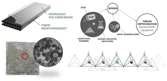
1. Introduction
2. Materials and Methods
Characterization of Materials
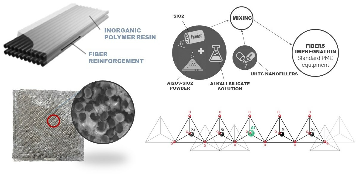
3. Results and Discussion
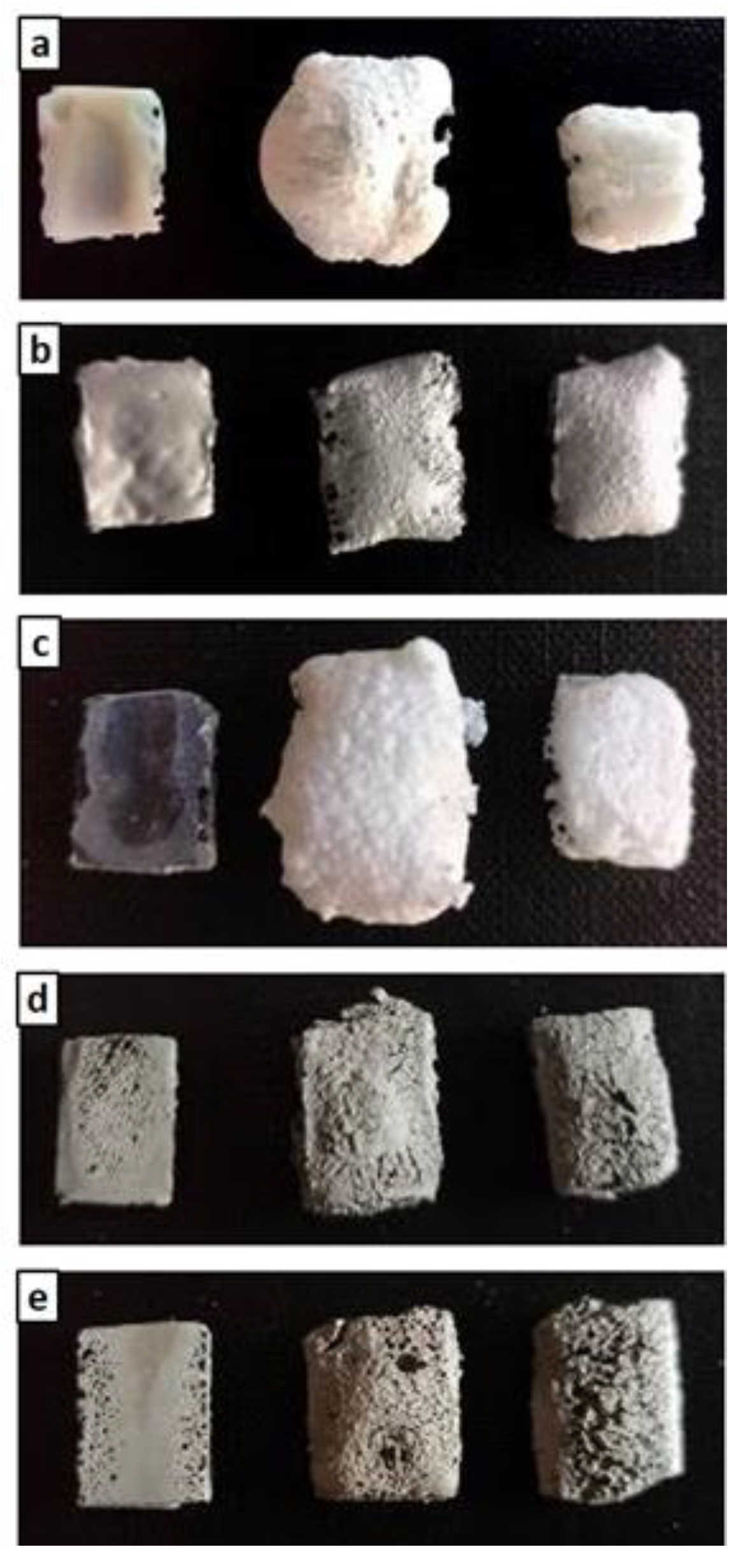
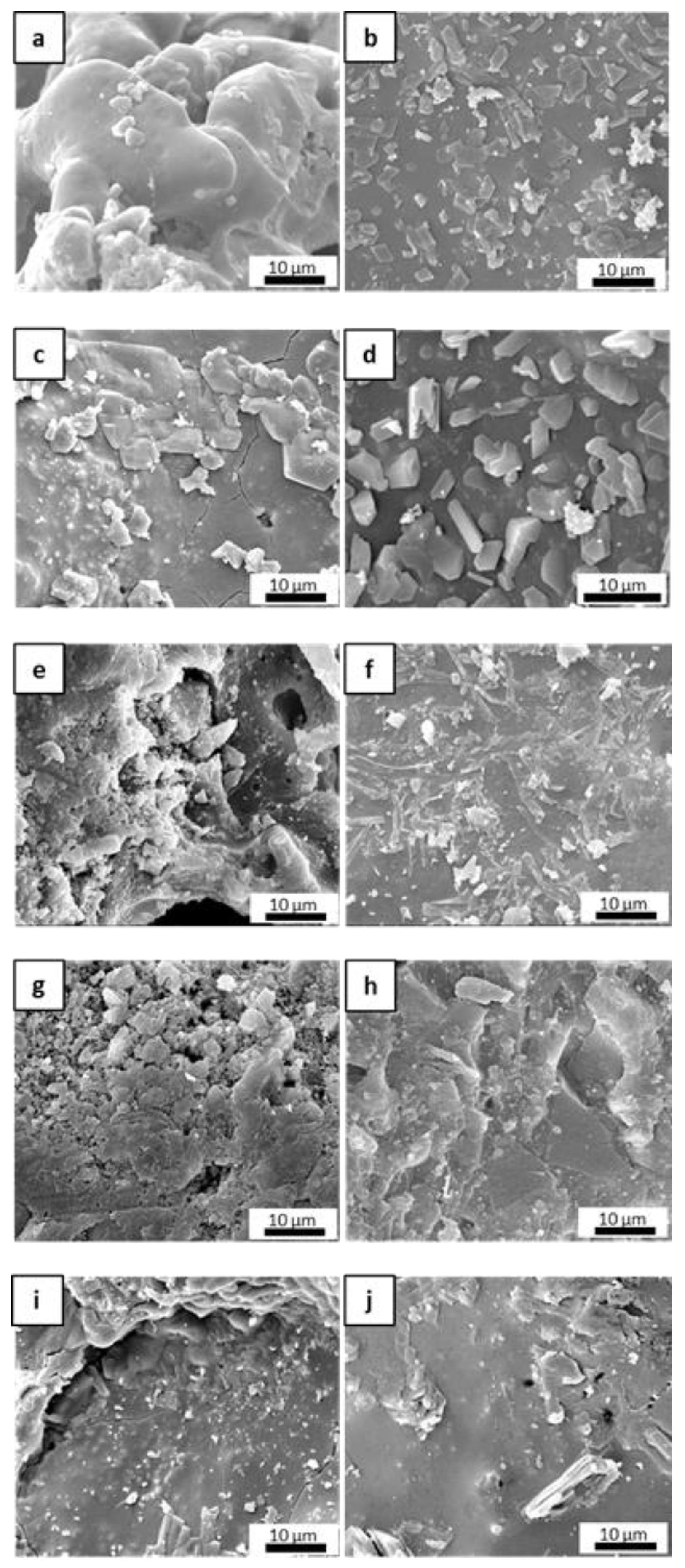
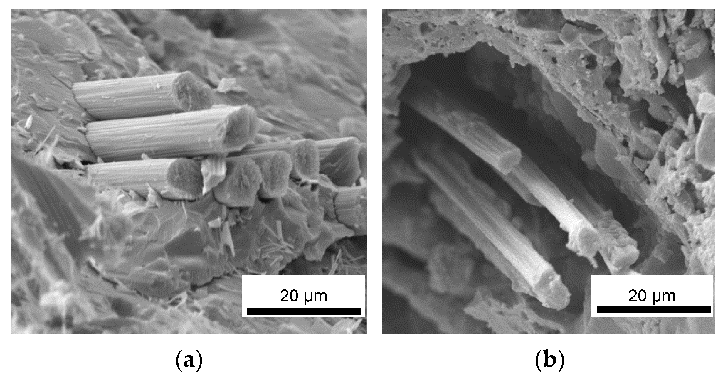
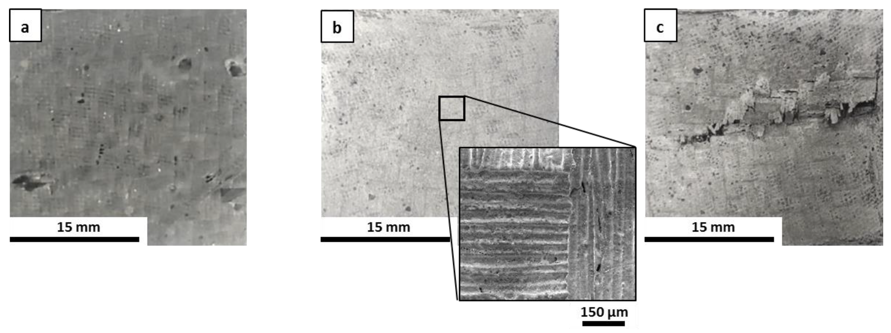
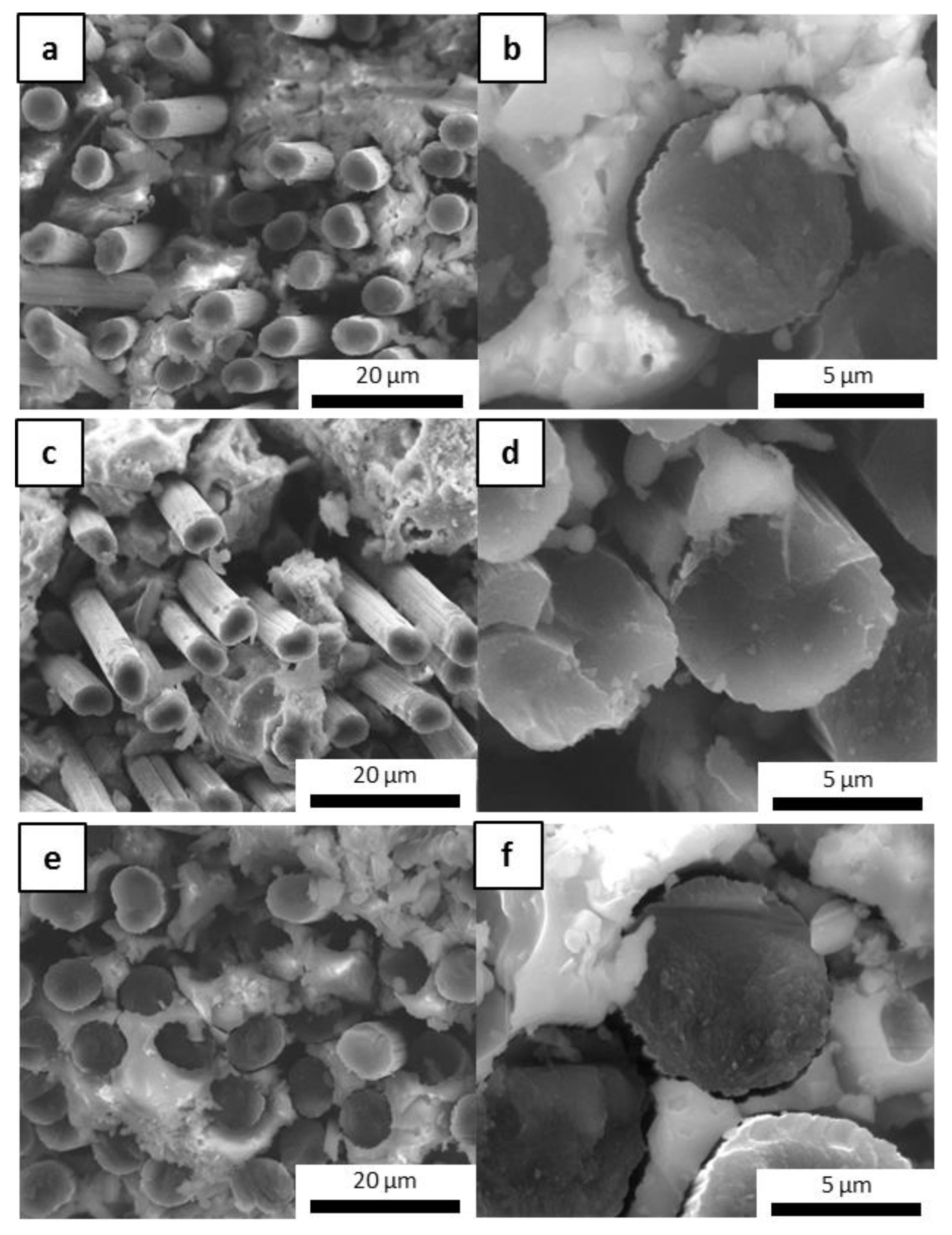
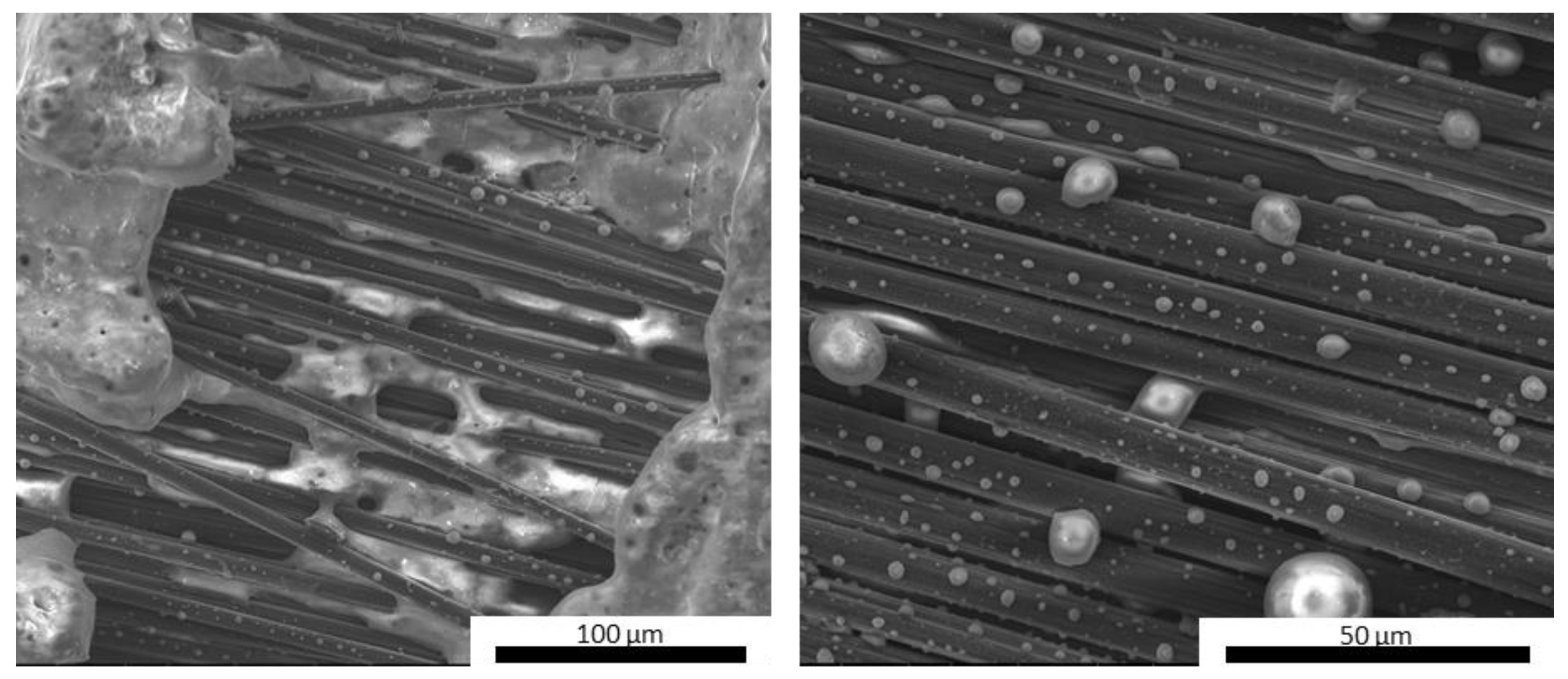
3.1. Microstructural Evaluations
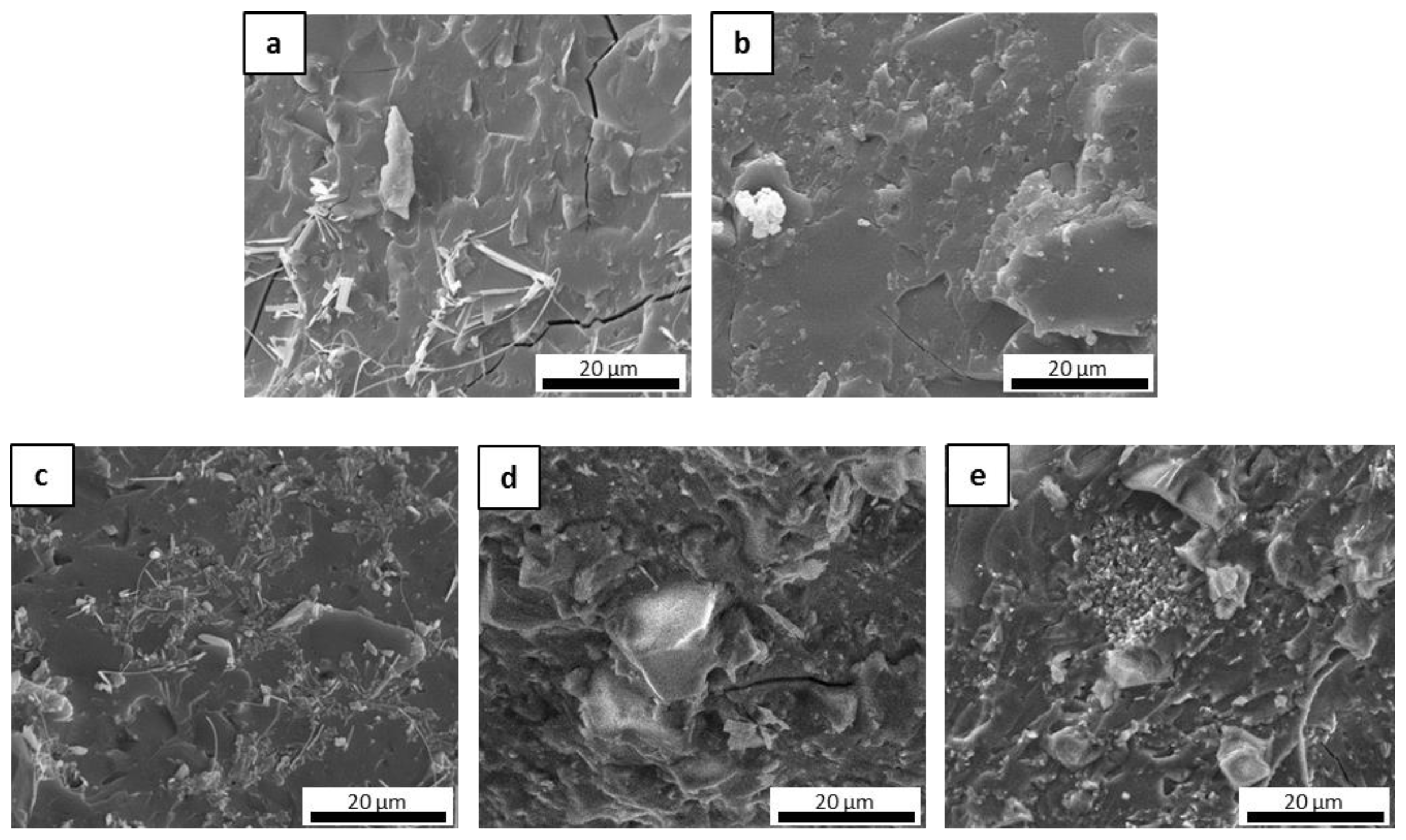
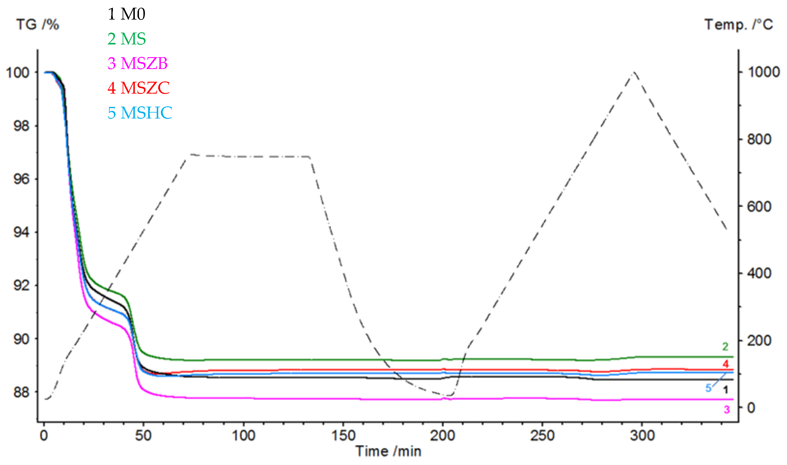
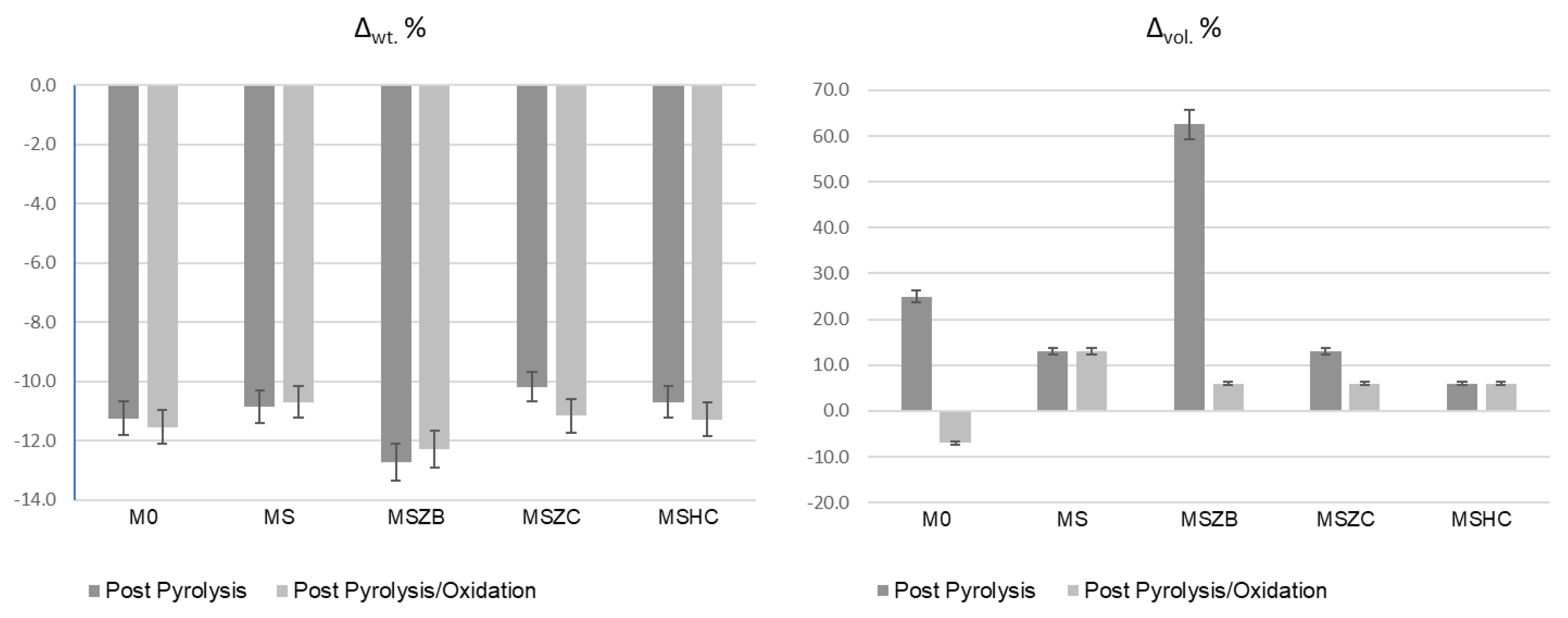
3.2. Thermal Behavior
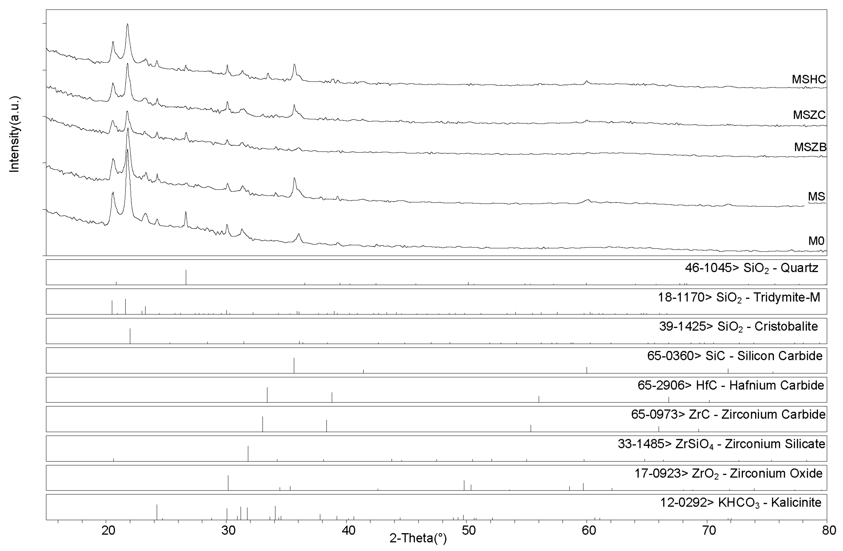
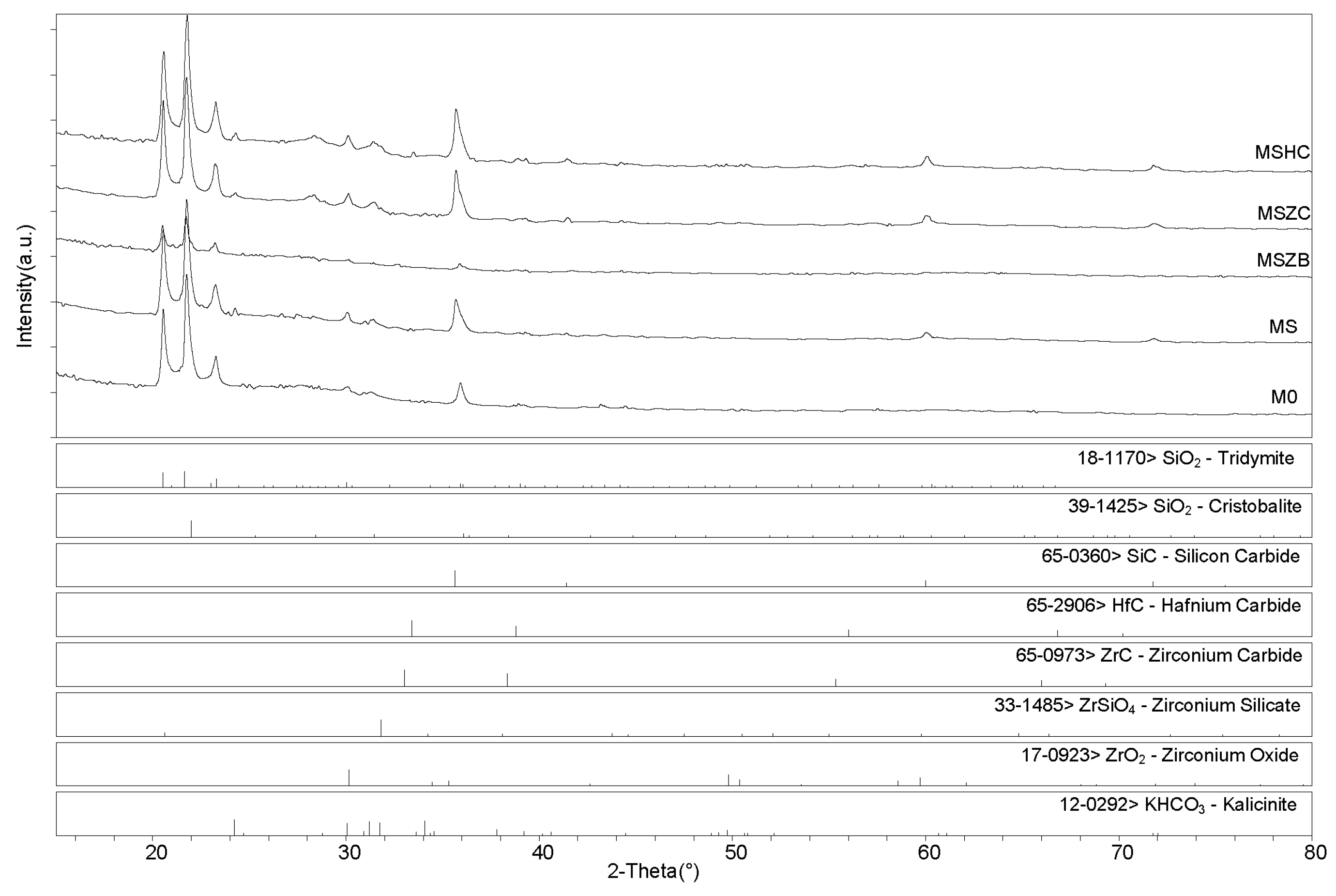
3.3. Phase Composition
3.4. Evaluation of the Fiber–Matrix Interface
3.5. Mechanical Properties

| Matrix | Fibers | Process | Fiber Fraction | Tensile Strength | Ultimate Strain | Young’s Modulus | Reference |
|---|---|---|---|---|---|---|---|
| (vol %) | (Mpa) | (%) | (Gpa) | ||||
| K-polysialate | SiC | HI-VB | 30 | 288 | 1.0 | 32 | [45] |
| K-poly(sialate siloxo) | C | HI-VB | 50 | 343 | - | 79 | [38] |
| K-polysialate | C | HI-VB | 50 | 332 | 0.67 | 76 | [40] |
| SiC | SiC | CVI | 40 | 255 | 0.47 | 230 | [62] |
| SiC | C | CVI | 40 | 204 | 0.35 | 88 | [63] |
| C | C | DPY | 60 | 225 | 0.25 | 100 | [64,65] |
| Mullite-SiOC | Al2O3 | PIP | 50 | 181 | - | 98 | [66] |
| Al2O3 | Al2O3 | SI | 37 | 170 | - | 145 | [66] |
| LAS glass | SiC | HP | 46 | 285 | - | - | [65,67] |
| BMAS glass | SiC | HP | 35 | 236 | 0.84 | 98 | [68] |
| CAS glass | SiC | CVI | 34 | 220 | 0.83 | 110 | [65,69] |
| DGEBA epoxy + 5%SiC | C/Glass/Kev | HI-VB | 60 | 322 | - | 14 | [70] |
| PEK | C | HI-VB | - | 425 | 9.4 | 7.8 | [71] |
| DGEBA epoxy | C | HI-VB | - | 311 | 11.3 | 5.2 | [71] |
| Araldite epoxy | C | HI-VB | 40 | 425 | 5.0 | 8.7 | [72] |
| Araldite epoxy | Glass | HI-VB | 40 | 112 | 4.0 | 2.9 | [72] |
| MS0-Cf K-poly (sialate-multisiloxo) | C | HI-VB | 35 | 136.7 | 1.4 | 37.4 | - |
4. Conclusions
Author Contributions
Funding
Institutional Review Board Statement
Informed Consent Statement
Data Availability Statement
Acknowledgments
Conflicts of Interest
References
- Gabrion, X.; Placet, V.; Trivaudey, F.; Boubakar, L. About the thermomechanical behaviour of a carbon fibre reinforced high-temperature thermoplastic composite. Compos. Part B Eng. 2016, 95, 386–394. [Google Scholar] [CrossRef]
- Volpe, V.; Lanzillo, S.; Affinita, G.; Villacci, B.; Macchiarolo, I.; Pantani, R. Lightweight High-Performance Polymer Composite for Automotive Applications. Polymers 2019, 11, 326. [Google Scholar] [CrossRef] [PubMed]
- Amran, Y.H.M.; Alyousef, R.; Rashid, R.S.M.; Alabduljabbar, H.; Hung, C.-C. Properties and applications of FRP in strengthening RC structures: A review. Structures 2018, 16, 208–238. [Google Scholar] [CrossRef]
- Rajak, D.K.; Pagar, D.D.; Menezes, P.L.; Linul, E. Fiber-reinforced polymer composites: Manufacturing, properties, and applications. Polymers 2019, 11, 1667. [Google Scholar] [CrossRef] [PubMed]
- Das, T.K.; Ghosh, P.; Das, N.C. Preparation, development, outcomes, and application versatility of carbon fiber-based polymer composites: A review. Adv. Compos. Hybrid Mater. 2019, 2, 214–233. [Google Scholar] [CrossRef]
- Asyraf, M.R.M.; Ilyas, R.A.; Sapuan, S.M.; Harussani, M.M.; Hariz, H.M.; Aiman, J.M.; Baitaba, D.M. Advanced Composite in Aerospace Applications: Opportunities, Challenges, and Future Perspective. In Advanced Composites in Aerospace Engineering Applications; Mazlan, N.S., Ed.; Springer: Berlin/Heidelberg, Germany, 2022; pp. 471–498. [Google Scholar]
- Fiore, V.; Valenza, A. Epoxy resins as a matrix material in advanced fiber-reinforced polymer (FRP) composites. In Advanced Fibre-Reinforced Polymer (FRP) Composites for Structural Applications; Woodhead Publishing: Thorston, UK, 2013; pp. 88–121. [Google Scholar]
- Yang, G.; Xian, G.; Li, H.; Su, L. Thermal aging of an anhydride-cured epoxy resin. Polym. Degrad. Stab. 2015, 118, 111–119. [Google Scholar] [CrossRef]
- Guermazi, N.; Tarjem, A.B.; Ksouri, I.; Ayedi, H.F. On the durability of FRP composites for aircraft structures in hygrothermal conditioning. Compos. Part B Eng. 2016, 85, 294–304. [Google Scholar] [CrossRef]
- Cohades, A.; Branfoot, C.; Rae, S.; Bond, I.; Michaud, V. Progress in Self-Healing Fiber-Reinforced Polymer Composite. Adv. Mater. Interfaces 2018, 5, 1800177. [Google Scholar] [CrossRef]
- Goh, G.D.; Toh, W.; Yap, Y.L.; Ng, T.Y.; Yeong, W.Y. Additively manufactured continuous carbon fiber-reinforced thermoplastic for topology optimized unmanned aerial vehicle structures. Compos. Part B Eng. 2021, 216, 108840. [Google Scholar] [CrossRef]
- Liu, Y.L. Flame-retardant epoxy resins from novel phosphorus-containing novolac. Polymer 2001, 42, 3445–3454. [Google Scholar] [CrossRef]
- Mercado, L.A.; Galia, M.; Reina, J.A. Silicon-containing flame retardant epoxy resins: Synthesis, characterization and properties. Polym. Degrad. Stab. 2006, 91, 2588–2594. [Google Scholar] [CrossRef]
- Liu, Q.; Wang, D.; Li, Z.; Peng, X.; Liu, C.; Zhang, Y.; Zheng, P. Recent developments in the flame-retardant system of epoxy resin. Materials 2020, 13, 2145. [Google Scholar] [CrossRef] [PubMed]
- Uthaman, A.; Xian, G.; Thomas, S.; Wang, Y.; Zheng, Q.; Liu, X. Durability of an epoxy resin and its carbon fiber-reinforced polymer composite upon immersion in water, acidic, and alkaline solutions. Polymers 2020, 12, 614. [Google Scholar] [CrossRef]
- Kimura, H.; Ohtsuka, K.; Yonekawa, M. Epoxy resins with high heat resistance and flame retardancy via a new process. Polym. Adv. Technol. 2021, 32, 474–483. [Google Scholar] [CrossRef]
- Liu, W.; Zhao, D.; Pan, Z.; Shen, Y.; Wang, T. Enhanced residue stability and strength of epoxy-based coating for fire protection via ceramifiable strategy. Prog. Org. Coat. 2021, 154, 106211. [Google Scholar] [CrossRef]
- Movahedifar, E.; Vahabi, H.; Saeb, M.R.; Thomas, S. Flame retardant epoxy composites on the road of innovation: An analysis with flame retardancy index for future development. Molecules 2019, 24, 3964. [Google Scholar] [CrossRef] [PubMed]
- Bansal, N.P.; Lamon, J. Ceramic Matrix Composites: Materials, Modeling and Technology; John Wiley & Sons: Hoboken, NJ, USA, 2014. [Google Scholar]
- Diaz, O.G.; Garcia Luna, G.; Liao, Z.; Axinte, D. The new challenges of machining Ceramic Matrix Composites (CMCs): Review of surface integrity. IJMTM 2019, 139, 24–36. [Google Scholar] [CrossRef]
- Heredia, F.E.; McNulty, J.C.; Zok, F.W.; Evans, A.G. Oxidation embrittlement probe for ceramic-matrix composites. J. Am. Ceram. Soc. 1995, 78, 2097–2100. [Google Scholar] [CrossRef]
- Lamouroux, F.; Bertrand, S.; Pailler, R.; Naslain, R.; Cataldi, M. Oxidation-resistant carbon-fiber-reinforced ceramic-matrix composites. Compos. Sci. Technol. 1999, 59, 1073–1085. [Google Scholar] [CrossRef]
- Boccaccini, A.R. Continuous fibre reinforced glass and glass-ceramic matrix composites. In Handbook of Ceramic Composites; Bansal, N.P., Ed.; Springer: Boston, MA, USA, 2005; pp. 461–484. [Google Scholar]
- Boccaccini, A.R.; Kaya, C. Glass and glass-ceramic matrix composite materials. J. Ceram. Soc. Jpn. 2001, 109, S99–S109. [Google Scholar] [CrossRef]
- Kriven, W.M.; Bell, J.L.; Gordon, M. Microstructure and microchemistry of fully-reacted geopolymers and geopolymer matrix composites. Ceram. Trans. 2003, 153, 227–250. [Google Scholar]
- Radford, D.W.; Grabher, A.; Bridge, J. Inorganic polymer matrix composite strength related to interface condition. Materials 2009, 2, 2216–2227. [Google Scholar] [CrossRef]
- Natali, A.; Manzi, S.; Bignozzi, M.C. Novel fiber-reinforced composite materials based on sustainable geopolymer matrix. Procedia Eng. 2011, 21, 1124–1131. [Google Scholar] [CrossRef]
- Rahman, A.S.; Jackson, P.; Radford, D.W. Improved toughness and delamination resistance in continuous fiber reinforced geopolymer composites via incorporation of nano-fillers. Cem. Concr. Compos. 2020, 108, 103496. [Google Scholar] [CrossRef]
- Ma, S.; Yang, H.; Zhao, S.; He, P.; Zhang, Z.; Duan, X.; Yang, Z.; Jia, D.; Zhou, Y. 3D-printing of architectured short carbon fiber-geopolymer composite. Compos. Part B Eng. 2021, 226, 109348. [Google Scholar] [CrossRef]
- Davidovits, J. Geopolymer Green Chemistry and Sustainable Development Solutions; Institut Géopolymère/Geopolymer Institute: Saint-Quentin, France, 2005; Volume 1, pp. 9–17. [Google Scholar]
- Duxson, P.; Fernández-Jiménez, A.; Provis, J.L.; Lukey, G.C.; Palomo, A.; van Deventer, J.S.J. Geopolymer technology: The current state of the art. J. Mater. Sci. 2007, 42, 2917–2933. [Google Scholar] [CrossRef]
- Hardjito, D.; Wallah, S.E.; Sumajouw, D.M.J.; Rangan, B.V. On the development of fly ash-based geopolymer concrete. Mater. J. 2004, 101, 467–472. [Google Scholar]
- Davidovits, J.; Davidovics, M. Geopolymer: Ultra-high temperature tooling material for the manufacture of advanced composites. In Proceedings of the How Concept Becomes Reality, 36th International SAMPE Symposium, San Diego, CA, USA, 15–18 April 1991; Volume 36, pp. 1939–1949. [Google Scholar]
- He, P.; Jia, D.; Lin, T.; Wang, M.; Zhou, Y. Effects of high-temperature heat treatment on the mechanical properties of unidirectional carbon fiber reinforced geopolymer composites. Ceram. Int. 2010, 36, 1447–1453. [Google Scholar] [CrossRef]
- Bernal, S.; Bejarano, J.; Garzón, C.; Mejía de Gutiérrez, R.; Delvasto, S.; Rodríguez, E.D. Performance of refractory aluminosilicate particle/fiber-reinforced geopolymer composites. Compos. Part B Eng. 2012, 43, 1919–1928. [Google Scholar] [CrossRef]
- Alzeer, M.; MacKenzie, K. Synthesis and mechanical properties of novel composites of inorganic polymers (geopolymers) with unidirectional natural flax fibres (phormium tenax). Appl. Clay Sci. 2013, 75–76, 148–152. [Google Scholar] [CrossRef]
- Rickard, W.D.A.; Vickers, L.; van Riessen, A. Performance of fibre reinforced, low density metakaolin geopolymers under simulated fire conditions. Appl. Clay Sci. 2013, 73, 71–77. [Google Scholar] [CrossRef]
- Lyon, R.E.; Balaguru, P.N.; Foden, A.; Sorathia, U.; Davidovits, J.; Davidovics, M. Fire-resistant aluminosilicate composites. Fire Mater. 1997, 21, 67–73. [Google Scholar] [CrossRef]
- Giancaspro, J.W.; Balaguru, P.N.; Lyon, R.E. Fire protection of flammable materials utilizing geopolymer. SAMPE J. 2004, 40, 42–49. [Google Scholar]
- Hammell, J.; Balaguru, P.; Lyon, R.E. Influence of reinforcement types on the flexural properties of geopolymer composites. In Materials and Process Affordability—Keys to the Future, 43rd International SAMPE Symposium, Anaheim, CA, USA, 31 May–4 June 1998; Books on Demand: Hamburg, Germany, 1998; pp. 1600–1608. [Google Scholar]
- Keane, P.F.; Foltz, J.S.; Chadha, V.; Marsh, C.P.; Kriven, W.M. Amorphous self-healed, chopped basalt fiber-reinforced, geopolymer composites. J. Am. Ceram. Soc. 2021, 104, 3443–3451. [Google Scholar] [CrossRef]
- Al-Majidi, M.H.; Lampropoulos, A.; Cundy, A.B. Tensile properties of a novel fibre reinforced geopolymer composite with enhanced strain hardening characteristics. Compos. Struct. 2017, 168, 402–427. [Google Scholar] [CrossRef]
- Davidovits, J. Chemistry of geopolymeric systems terminology. In Second International Conference Geopolymer; Davidovits, J., Davidovits, R., James, C., Eds.; Institut Géopolymère: Saint-Quentin, France, 1999; pp. 9–39. [Google Scholar]
- Farrugia, A.; Dusserre, G.; Cutard, T.; Rollin, M. Processing glass-ceramic matrix composites by liquid moulding: Characterisation of the rheology of a resin derived from a geopolymeric system. In Proceedings of the ECCM 15-15th European Conference on Composite Materials, Venice, Italy, 24–28 June 2012. [Google Scholar]
- Mills-Brown, J.; Potter, K.; Foster, S.; Batho, T. Thermal and tensile properties of polysialate composites. Ceram. Int. 2013, 39, 8917–8924. [Google Scholar] [CrossRef]
- Han, S.; Chung, D.D.L. Strengthening and stiffening carbon fiber epoxy composites by halloysite nanotubes, carbon nanotubes and silicon carbide whiskers. Appl. Clay Sci. 2013, 83–84, 375–382. [Google Scholar] [CrossRef]
- Paul, A.; Venugopal, S.; Binner, J.G.P.; Vaidhyanathan, B.; Heaton, A.C.J.; Brown, P.M. UHTC–carbon fibre composites: Preparation, oxyacetylene torch testing and characterisation. J. Eur. Ceram. Soc. 2013, 33, 423–432. [Google Scholar] [CrossRef]
- Du, F.; Xie, S.; Zhang, F.; Tang, C.; Chen, L.; Law, W.; Tsui, C. Microstructure and compressive properties of silicon carbide reinforced geopolymer. Compos. Part B Eng. 2016, 105, 93–100. [Google Scholar] [CrossRef]
- Fahrenholtz, W.G.; Hilmas, G.E. Ultra-high temperature ceramics: Materials for extreme environments. Scr. Mater. 2017, 129, 94–99. [Google Scholar] [CrossRef]
- Savino, R.; Criscuolo, L.; Di Martino, G.D.; Mungiguerra, S. Aero-thermo-chemical characterization of ultra-high-temperature ceramics for aerospace applications. J. Eur. Ceram. Soc. 2018, 38, 2937–2953. [Google Scholar] [CrossRef]
- Rahman, A.S.; Radford, D.W. Cure cycle optimization of an inorganic polymer matrix material for high temperature fiber reinforced composites. Compos. Part A Appl. Sci. Manuf. 2016, 85, 84–93. [Google Scholar] [CrossRef]
- Servadei, F.; Zoli, L.; Galizia, P.; Vinci, A.; Sciti, D. Development of UHTCMCs via water based ZrB2 powder slurry infiltration and polymer infiltration and pyrolysis. J. Eur. Ceram. Soc. 2020, 40, 5076–5084. [Google Scholar] [CrossRef]
- Cuiyan, L.; Guibiao, L.; Haibo, O.; Jing, L. ZrB2 particles reinforced glass coating for oxidation protection of carbon/carbon composites. J. Adv. Ceram. 2019, 8, 102–111. [Google Scholar]
- Medri, V.; Ruffini, A. Alkali-bonded SiC based foams. J. Eur. Ceram. Soc. 2012, 32, 1907–1913. [Google Scholar] [CrossRef]
- Purwar, A.; Basu, B. Thermo-structural design of ZrB2–SiC based thermal protection system for hypersonic space vehicles. J. Am. Ceram. Soc. 2017, 100, 1618–1633. [Google Scholar] [CrossRef]
- Ortiz, V.; Zamora, F.A. Rodríguez-Rojas. A study of the oxidation of ZrB2 powders during high-energy ball-milling in air. Ceram. Int. 2012, 38, 2857–2863. [Google Scholar] [CrossRef]
- Naraparaju, R.; Maniya, K.; Murchie, A.; Fahrenholtz, W.; Hilmas, G. Effect of moisture on the oxidation behavior of ZrB2. J. Am. Ceram. Soc. 2020, 104, 1058–1066. [Google Scholar] [CrossRef]
- Chadha, V.; Kriven, W.M. Amorphous self-glazed, chopped basalt fiber reinforced, geopolymer-based composites. Int. J. Appl. Ceram. 2021, 18, 1097–1105. [Google Scholar] [CrossRef]
- ASTM D3039; Standard Test Method for Tensile Properties of Polymer Matrix Composite Materials. ASTM International: West Conshohocken, PA, USA, 2017.
- Sadat, M.R.; Bringuier, S.; Muralidharan, K.; Runge, K.; Asaduzzaman, A.; Zhang, L. An atomistic characterization of the interplay between composition, structure and mechanical properties of amorphous geopolymer binders. J. Non-Cryst. Solids 2016, 434, 53–61. [Google Scholar] [CrossRef]
- Ray, S.K.; Singh, K.K.; Ansari, M.T.A. Effect of small ply angle variation in tensile and compressive strength of woven GFRP composite: Application of two parameter Weibull distribution. Mater. Today Proc. 2020, 33, 5295–5300. [Google Scholar] [CrossRef]
- Lehman, R.L.; El-Rahaiby, S.K.; Wachtman, J.B., Jr. Handbook on Continuous Fiber-Reinforced Ceramic Matrix Composites; Purdue University Office Pubns: West Lafayette, IN, USA, 1995; pp. 240–241. [Google Scholar]
- Li, L.B.; Song, Y.D.; Sun, Y.C. Modeling the tensile behavior of cross-ply C/SiC ceramic-matrix composites. Mech. Compos. Mater. 2015, 51, 359–376. [Google Scholar] [CrossRef]
- Hatta, H.; Suzuki, K.; Shigei, T.; Somiya, S.; Sawada, Y. Strength improvement by densification of C/C composites. Carbon 2001, 39, 83–90. [Google Scholar] [CrossRef]
- Papakonstantinou, C.G.; Balaguru, P.; Lyon, R.E. Comparative study of high temperature composites. Compos. Part B Eng. 2001, 32, 637–649. [Google Scholar] [CrossRef]
- Volkmann, E.; Tushtev, K.; Koch, D.; Wilhelmi, C.; Göring, J.; Rezwan, K. Assessment of three oxide/oxide ceramic matrix composites: Mechanical performance and effects of heat treatments. Compos. A Appl. Sci. 2015, 68, 19–28. [Google Scholar] [CrossRef]
- Prewo, K.M. Tension and flexural strength of silicon carbide fibre-reinforced glass ceramics. J. Mater. Sci. 1986, 21, 3590–3600. [Google Scholar] [CrossRef]
- Sun, E.Y.; Nutt, S.R.; Brennan, J.J. High-temperature tensile behavior of a boron nitride-coated silicon carbide-fiber glass-ceramic composite. J. Am. Ceram. Soc. 1996, 79, 1521–1529. [Google Scholar] [CrossRef]
- Blissett, M.J.; Smith, P.A.; Yeomans, J.A. Flexural mechanical properties of thermally treated unidirectional and cross-ply nicalon-reinforced calcium aluminosilicate composites. J. Mater. Sci. 1998, 33, 4181–4190. [Google Scholar] [CrossRef]
- Karthik, K.; Prakash, J.U.; Binoj, J.S.; Mansingh, B.B. Effect of stacking sequence and silicon carbide nanoparticles on properties of carbon/glass/Kevlar fiber reinforced hybrid polymer composites. Polym. Compos. 2022, 43, 6096–6105. [Google Scholar] [CrossRef]
- Sudhin, A.U.; Remanan, M.; Ajeesh, G.; Jayanarayanan, K. Comparison of properties of carbon fiber reinforced thermoplastic and thermosetting composites for aerospace applications. Mater. Today Proc. 2020, 24, 453–462. [Google Scholar] [CrossRef]
- Khan, Z.I.; Arsad, A.; Mohamad, Z.; Habib, U.; Zaini, M.A.A. Comparative study on the enhancement of thermo-mechanical properties of carbon fiber and glass fiber reinforced epoxy composites. Mater. Today Proc. 2021, 39, 956–958. [Google Scholar] [CrossRef]


| Density (g/cm3) | D10 (µm) | D50 (µm) | D90 (µm) | SSA (m2/g) | |
|---|---|---|---|---|---|
| β-SiC | 3.21 | 0.30 * | 1.10 * | 2.07 * | 11.6 * |
| ZrB2 | 6.10 | 1.15 | 2.92 | 4.70 | 1.0 * |
| ZrC | 6.73 | 1.72 | 7.30 | 17.28 | 0.87 |
| HfC | 12.69 | 0.29 | 0.80 | 5.0 | 1.19 |
| Composition (wt %) | |||||
|---|---|---|---|---|---|
| Sample | M0 | SiC | ZrB2 | ZrC | HfC |
| M0 | 100 | 0 | 0 | 0 | 0 |
| MS | 95 | 5 | 0 | 0 | 0 |
| MSZB | 95 | 4 | 1 | 0 | 0 |
| MSZC | 95 | 4 | 0 | 1 | 0 |
| MSHC | 95 | 4 | 0 | 0 | 1 |
Disclaimer/Publisher’s Note: The statements, opinions and data contained in all publications are solely those of the individual author(s) and contributor(s) and not of MDPI and/or the editor(s). MDPI and/or the editor(s) disclaim responsibility for any injury to people or property resulting from any ideas, methods, instructions or products referred to in the content. |
© 2023 by the authors. Licensee MDPI, Basel, Switzerland. This article is an open access article distributed under the terms and conditions of the Creative Commons Attribution (CC BY) license (https://creativecommons.org/licenses/by/4.0/).
Share and Cite
Medri, V.; Natali Murri, A.; Papa, E.; Mingazzini, C.; Scafè, M.; Landi, E. Ultra-High-Temperature Ceramic-Doped Inorganic Polymers for Thermo-Structural Fiber-Reinforced Composites. Materials 2023, 16, 6649. https://doi.org/10.3390/ma16206649
Medri V, Natali Murri A, Papa E, Mingazzini C, Scafè M, Landi E. Ultra-High-Temperature Ceramic-Doped Inorganic Polymers for Thermo-Structural Fiber-Reinforced Composites. Materials. 2023; 16(20):6649. https://doi.org/10.3390/ma16206649
Chicago/Turabian StyleMedri, Valentina, Annalisa Natali Murri, Elettra Papa, Claudio Mingazzini, Matteo Scafè, and Elena Landi. 2023. "Ultra-High-Temperature Ceramic-Doped Inorganic Polymers for Thermo-Structural Fiber-Reinforced Composites" Materials 16, no. 20: 6649. https://doi.org/10.3390/ma16206649