
Investigating Mechanical Properties of Alkali-Activated Slag Cementitious Material for Load-Bearing Layer of Sandwich Panels
 ,
,
Abstract
:1. Introduction
2. Material Proportions and Experimental Design
2.1. Materials
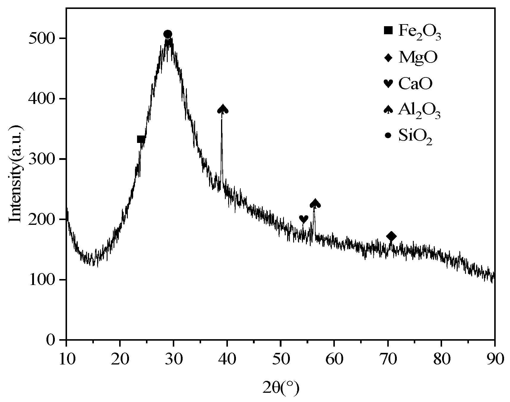
2.1.1. Slag
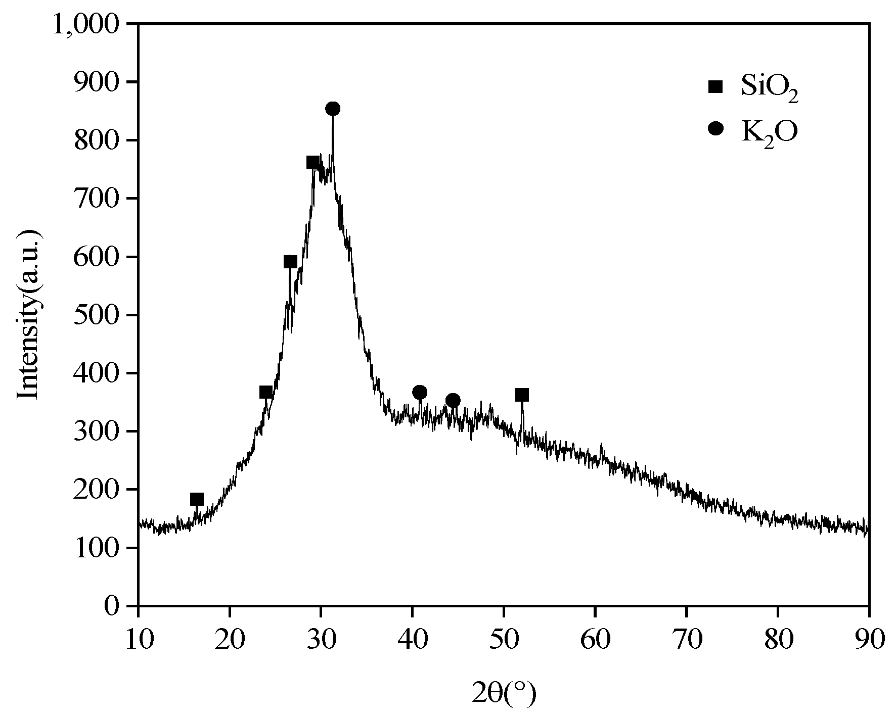
2.1.2. Potassium Silicate
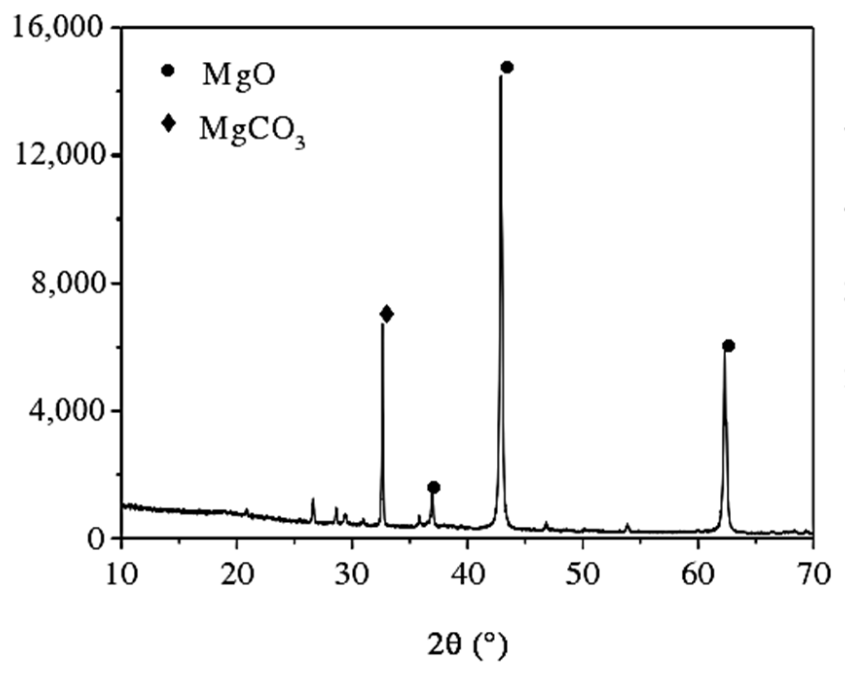
2.1.3. Magnesium Oxide
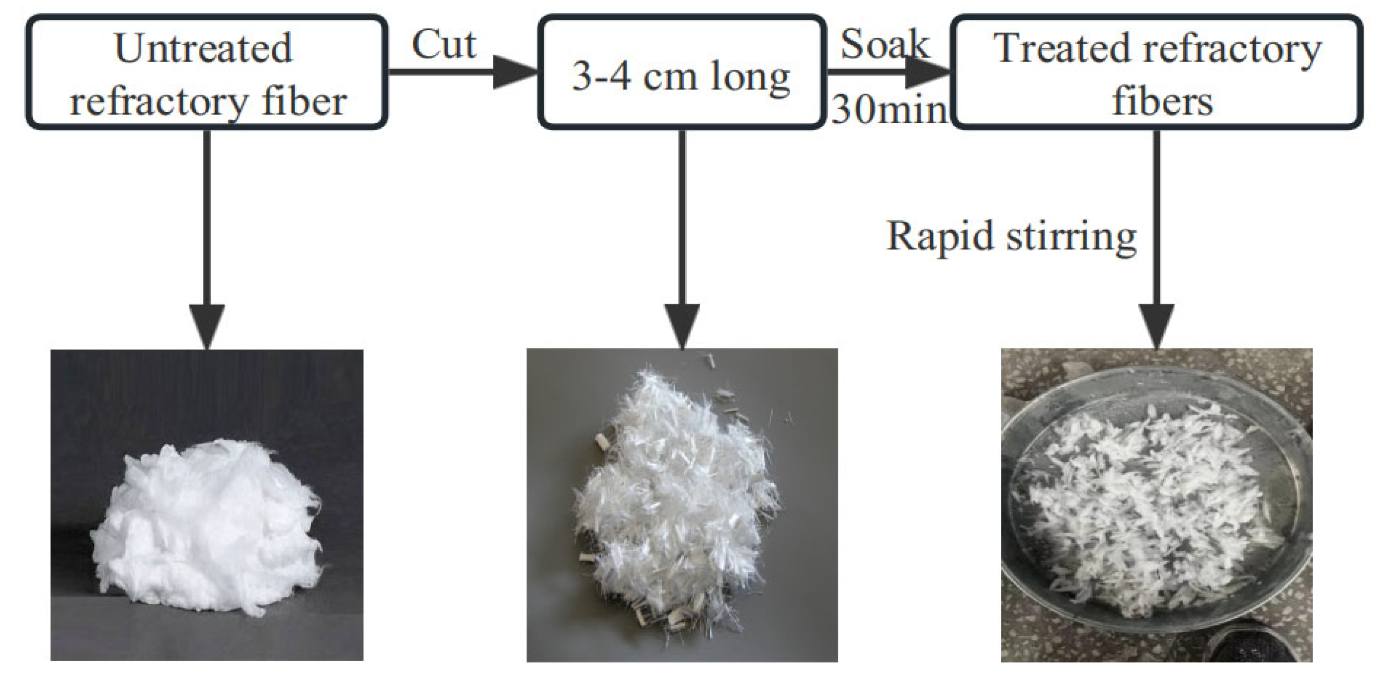
2.1.4. Refractory Fiber
2.1.5. Other Reagents
2.2. Mix Ratio Design
2.2.1. Adjusting the Modulus of Potassium Silicate to 1.0
2.2.2. Treatment of Refractory Fibers
2.2.3. Mix Ratio Design
2.3. Testing Methods
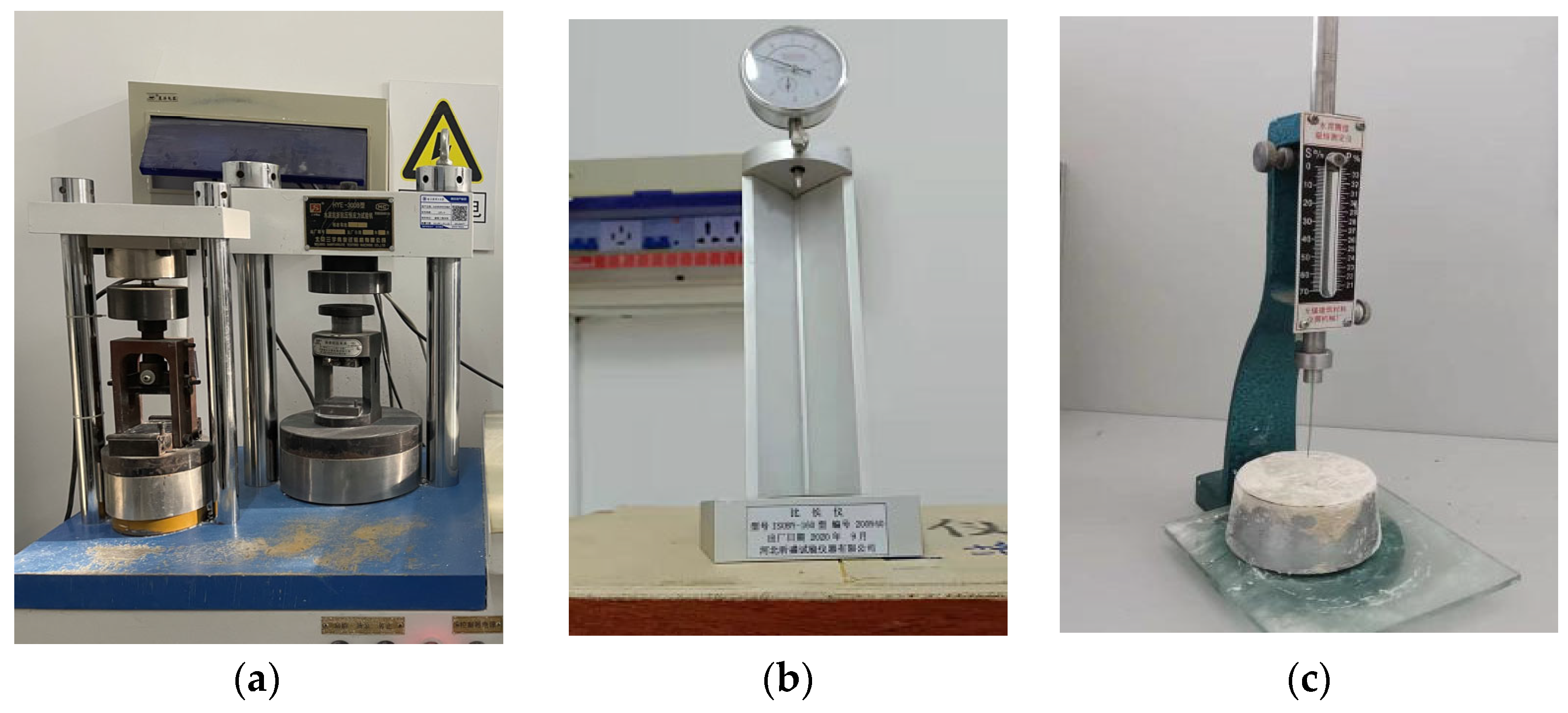
2.3.1. Compressive and Flexural Strength Tests
- Add an appropriate amount of sodium hydroxide to the potassium silicate with a modulus of 2.79 and stir well to adjust the modulus to 1.0.
- Pour slag and MgO into the NJ-160A cement mortar mixer according to the proportion, and mix at low speed for 1 min at a speed of 140 r/min to achieve a uniform powder mixture.
- Pour the potassium silicate, water and refractory fibers into the mixer and mix at low speed for 2 min at a speed of 140 r/min, followed by high-speed mixing for 2 min at a speed of 285 r/min.
- Pour the mixed slurry into 40 × 40 × 160 mm prismatic three-gang molds, ensuring the slurry covers the entire mold to prevent size deficiencies in the specimens due to slurry leakage during compaction, which may lead to incorrect flexural and compressive strength results.
- Compact the slurry on a vibrating table 120 times, and then, place the molds in a curing chamber with a standard temperature of 20 ± 2 °C and a relative humidity of 95% for curing. Demold the specimens after 1 day of curing.
2.3.2. Drying Shrinkage Test
2.3.3. Setting Time Test
2.3.4. Microstructural Analysis Methods
- (1)
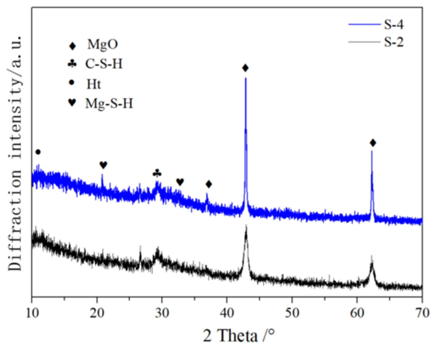
- X-ray Diffractometer (XRD): XRD tests were performed on the samples from the specimens using D8-Advance from Bruker Corporation (Billerica, MA, USA). To prepare the testing samples, the specimens were crushed and grinded into powder and then passed through a 0.075 mm sieve. The powder was dried in a beaker at 40 °C until a constant weight was achieved. The phases were scanned using an XRD instrument with a measurement accuracy of ≤0.010 and the scanning range of 10–70°.
- (2)
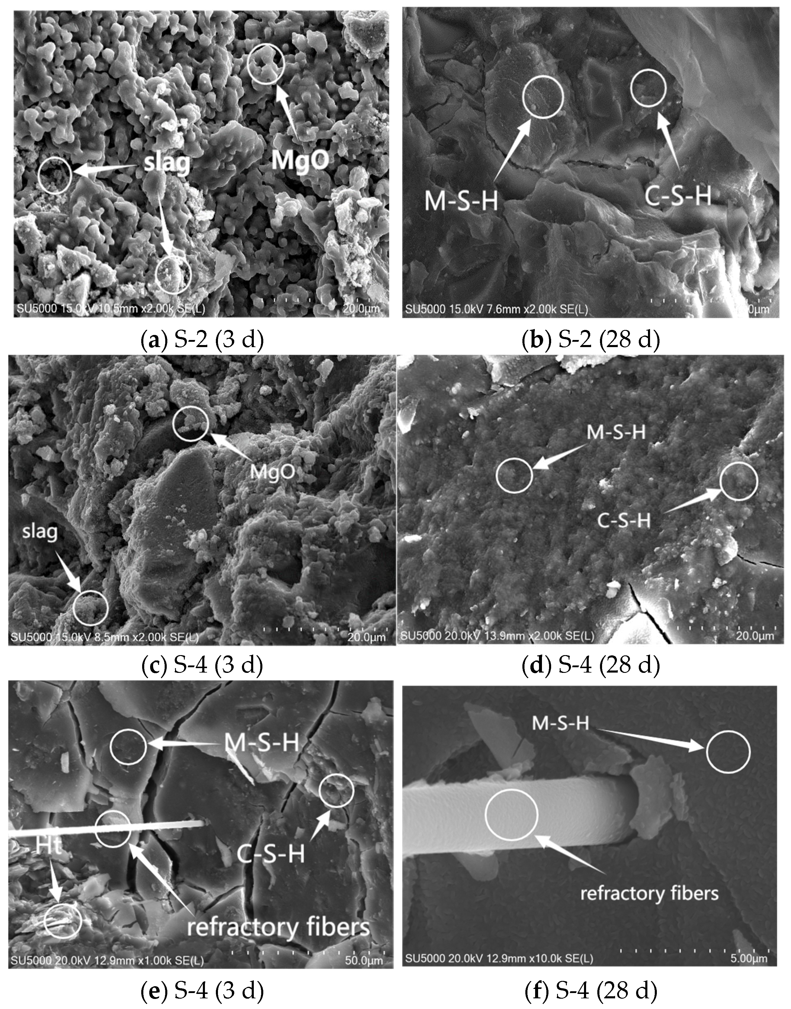
- Scanning Electron Microscope (SEM): SEM analyses were performed on the specimens using SUPERTM 55 from Carl Zeiss AG (Oberkochen, Germany). The testing samples were prepared as follows: (a) the broken center parts of the specimens with a curing age of 3 d and 28 d were placed in anhydrous ethanol to stop hydration; (b) after soaking for 7 days, the samples were dried at 60 °C in an oven until a constant weight was achieved; and (c) the samples were then attached to a tray and coated with gold. After gold coating, the SEM analysis was performed.
3. Results and Discussions
3.1. Effect of Admixture on Mechanical Properties of AASCM
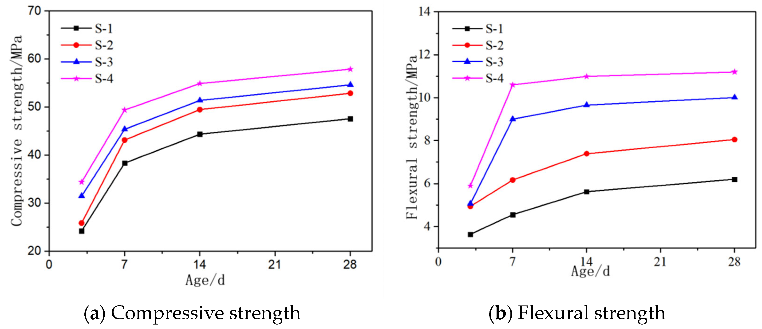
3.1.1. MgO Content
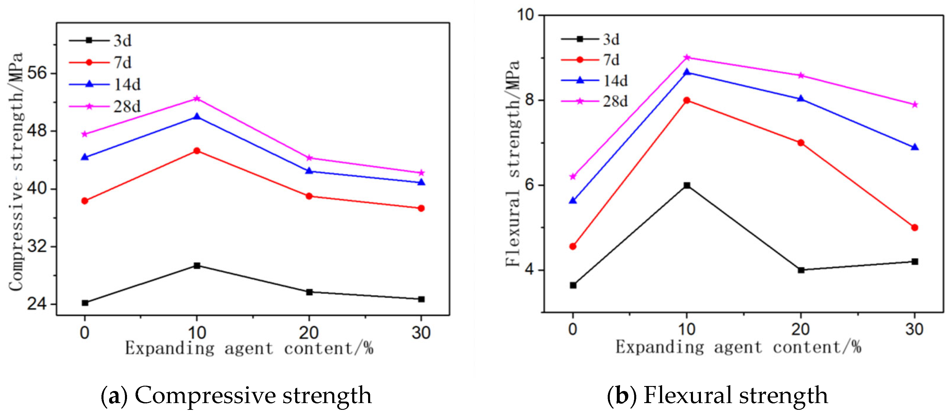
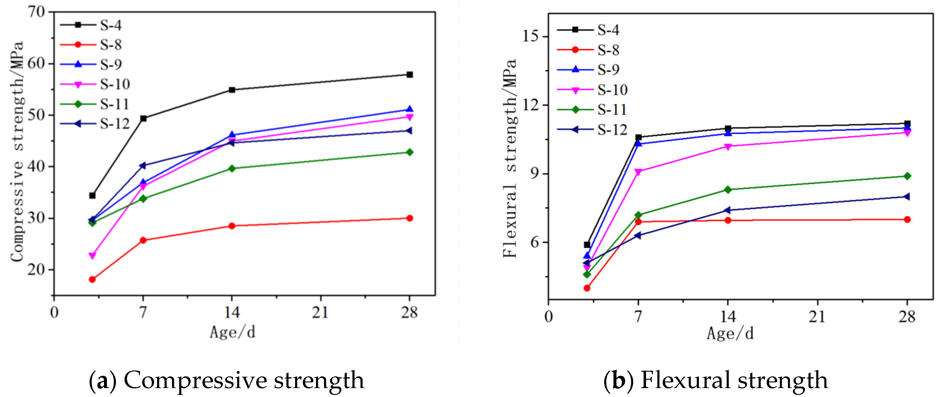
3.1.2. Partial Replacement of MgO with CaO
3.1.3. Other Admixtures
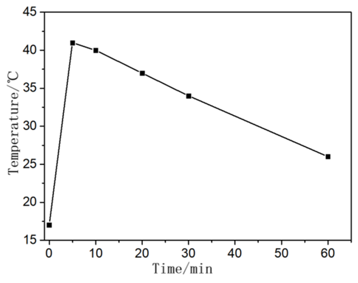
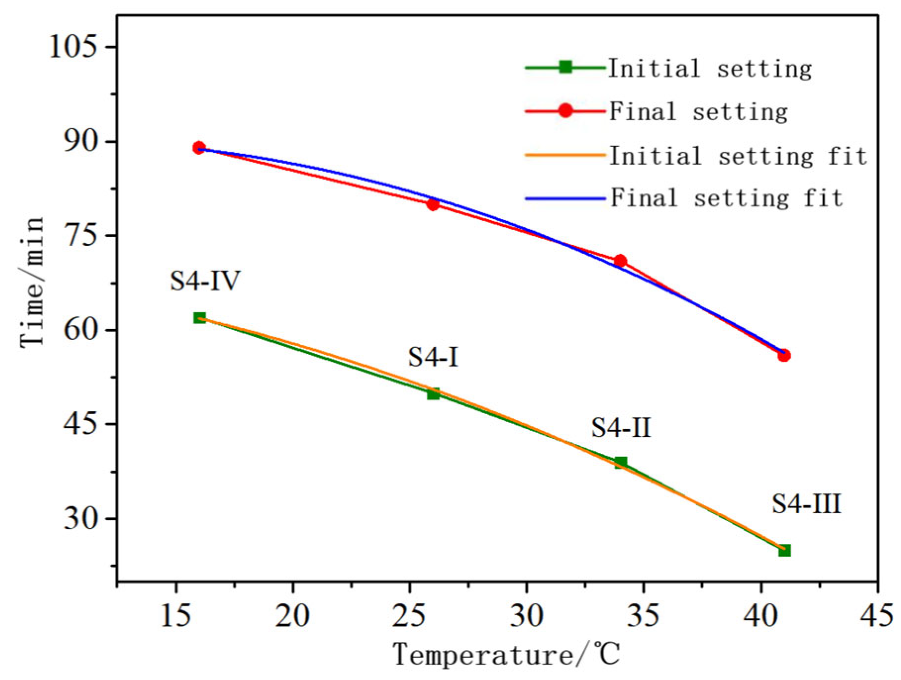
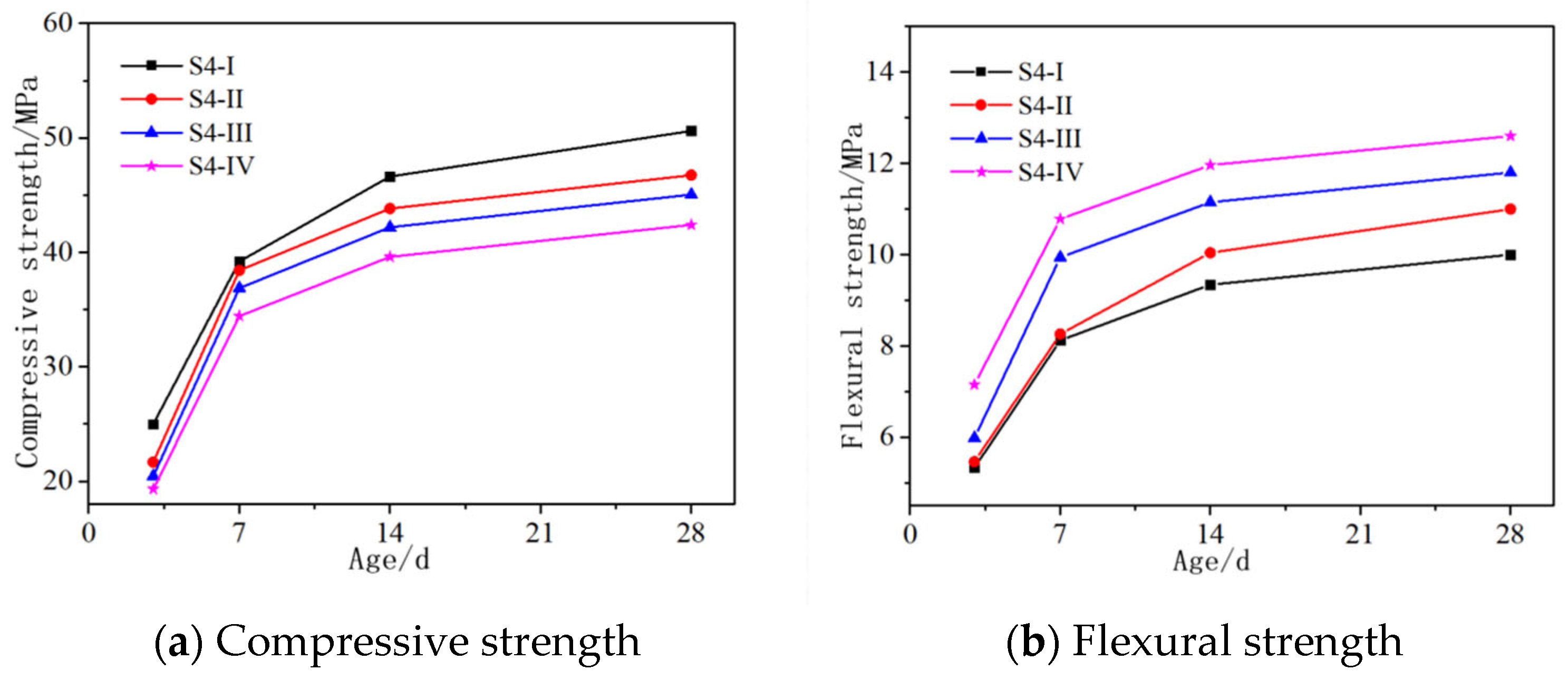
3.2. The Influence of Solution Temperature
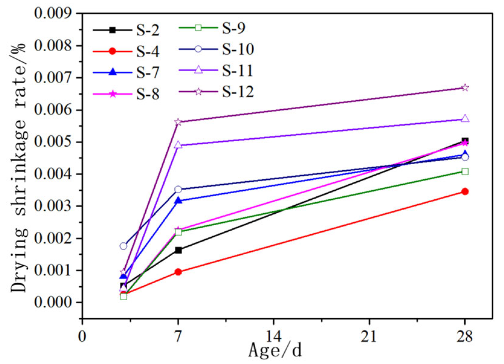
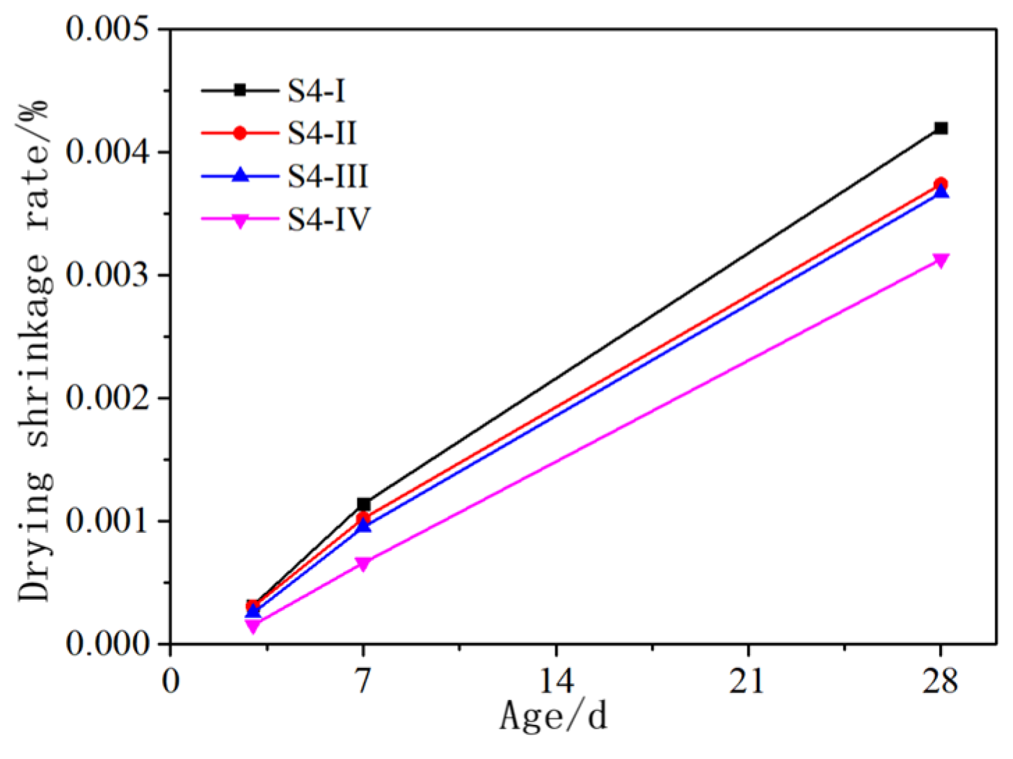
3.3. The Influence of Admixtures and Solution Temperature on the Drying Shrinkage of AASCM
3.4. Microscopic Analysis
3.4.1. X-ray Diffraction Analysis
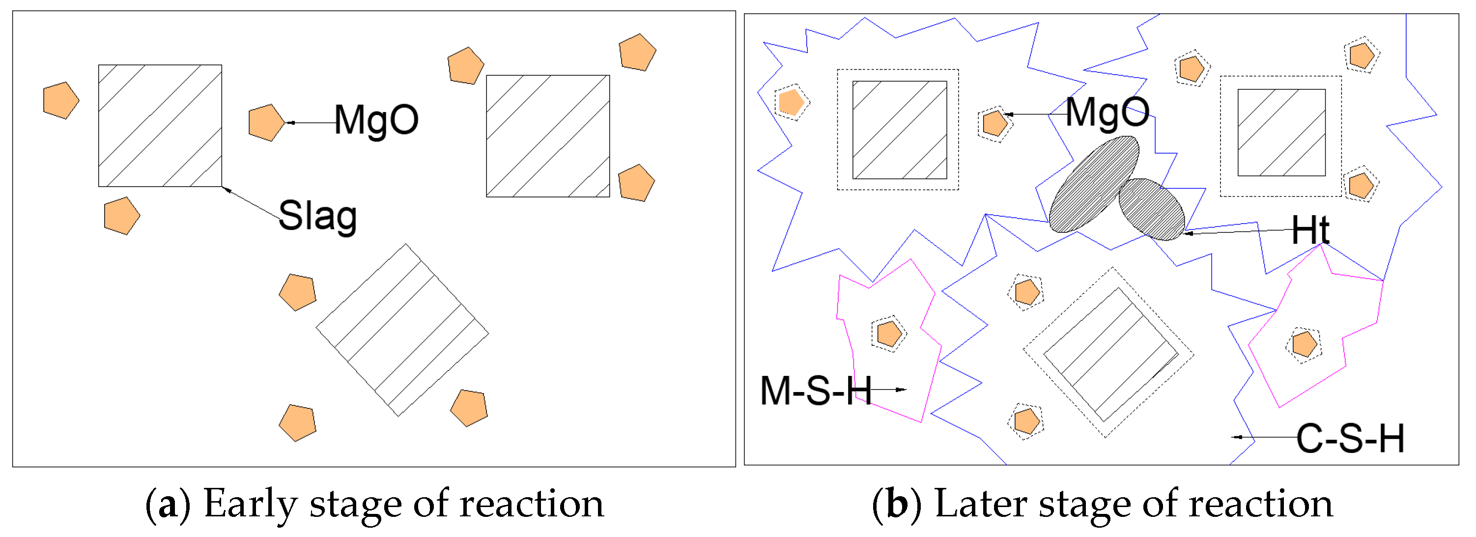
3.4.2. SEM Analysis
4. Conclusions
Author Contributions
Funding
Institutional Review Board Statement
Informed Consent Statement
Data Availability Statement
Conflicts of Interest
References
- Huang, J.; Xu, Y.; Huang, H.; Dai, J. Structural behavior of FRP connector enabled precast geopolymer concrete sandwich panels subjected to one-side fire exposure. Fire Saf. J. 2022, 128, 103524. [Google Scholar] [CrossRef]
- Gaibor, N.; Mateus, R.; Leitao, D.; Cristelo, N.; Miranda, T.; Pereira, E.N.; Cunha, V.M. Sustainability assessment of half-sandwich panels based on alkali-activated ceramic/slag wastes cement versus conventional building solutions. J. Clean. Prod. 2023, 389, 136108. [Google Scholar] [CrossRef]
- Kumar, S.; Das, C.S.; Lao, J.; Alrefaei, Y.; Dai, J.G. Effect of sand content on bond performance of engineered geopolymer composites (EGC) repair material. Constr. Build. Mater. 2022, 328, 127080. [Google Scholar] [CrossRef]
- Glukhovsky, V.D.; Rostovskaja, G.S.; Rumyna, G.V. High Strength Slag-Alkaline Cements. In Proceedings of the 7th International Congress on the Chemistry of Cement, Paris, France, 3–6 September 1980. [Google Scholar]
- Ranjbar, N.; Zhang, M. Fiber-reinforced geopolymer composites: A review. Cem. Concr. Compos. 2020, 107, 103498. [Google Scholar] [CrossRef]
- Choi, J.I.; Park, S.E.; Kim, Y.Y.; Lee, B.Y. Flexural behavior of composite beams of Kagome truss and fiber-reinforced cementitious composites. Constr. Build. Mater. 2022, 361, 129653. [Google Scholar] [CrossRef]
- Cui, Y.; Hao, H.; Li, J.; Chen, W.; Zhang, X. Structural behavior and vibration characteristics of geopolymer composite lightweight sandwich panels for prefabricated buildings. J. Build. Eng. 2022, 57, 104872. [Google Scholar] [CrossRef]
- Mavroulidou, M.; Sanam, I.; Mengasini, L. Mechanical and durability performance of alkali-activated slag cement concretes with carbonate and silicate activators. Sustain. Chem. Pharm. 2023, 31, 100896. [Google Scholar] [CrossRef]
- Manalo, A.C. Recent developments on fibre composite sandwich structures in civil infrastructure. In Proceedings of the 6th International Composites Conference (ACUN 6), Melbourne, Australia, 14–16 November 2012. [Google Scholar]
- Liu, X.; Wang, X.; Yang, T.; Wu, Z. The Shear Behavior of Insulated Precast Concrete Sandwich Panels Reinforced with BFRP. Buildings 2022, 12, 1326. [Google Scholar] [CrossRef]
- Tomlinson, D.; Fam, A. Analysis and parametric study of partially composite precast concrete sandwich panels under axial loads. J. Build. Eng. 2016, 142, 04016086. [Google Scholar] [CrossRef]
- Alchaar, A.; Abed, F. Finite element analysis of a thin-shell concrete sandwich panel under eccentric loading. J. Build. Eng. 2020, 32, 101804. [Google Scholar] [CrossRef]
- Korniejenko, K.; Figiela, B.; Miernik, K.; Ziejewska, C.; Marczyk, J.; Hebda, M.; Lin, W.T. Mechanical and Fracture Properties of Long Fiber Reinforced Geopolymer Composites. Materials 2021, 14, 5183. [Google Scholar] [CrossRef]
- Behfarnia, K.; Shahbaz, M. The effect of elevated temperature on the residual tensile strength and physical properties of the alkali-activated slag concrete. J. Build. Eng. 2018, 20, 442–454. [Google Scholar] [CrossRef]
- Mikhailova, O.; Šimonová, H.; Topolář, L.; Rovnaník, P. Influence of Polymer Additives on Mechanical Fracture Properties and on Shrinkage of Alkali Activated Slag Mortars. Key Eng. Mater. 2018, 761, 39–44. [Google Scholar] [CrossRef]
- Aydın, S. A ternary optimisation of mineral additives of alkali activated cement mortars. Constr. Build. Mater. 2013, 43, 131–138. [Google Scholar] [CrossRef]
- Zhu, J.; Song, L.; Qu, Z.; Wang, X.; Wen, Z.; Liu, X.; Wang, H. Mechanical Strengths of Alkali-Activated Blast Furnace Slag Powder with Different Alkali Activators and Plant Fibers. Coatings 2023, 13, 664. [Google Scholar] [CrossRef]
- Feng, S.; Zhu, J.; Wang, R.; Qu, Z.; Song, L.; Wang, H. The Influence of CaO and MgO on the Mechanical Properties of Alkali-Activated Blast Furnace Slag Powder. Materials 2022, 15, 6128. [Google Scholar] [CrossRef] [PubMed]
- Shen, C.; Fang, X.; Wang, H. Study on the influence of suction, moisture content, and dry density on the shear strength of remolded unsaturated soil. Rock Soil Mech. 2009, 30, 1347–1351. [Google Scholar]
- JGJ/T70-2009; Standard for Test Method of Performance on Building Mortar. Industry Standard—Construction Industry: Beijing, China, 2009.
- Wu, H.; Jin, F.; Zhou, A.; Du, Y. The engineering properties and reaction mechanism of MgO-activated slag cement-clayey sand-bentonite (MSB) cutoff wall backfills. Constr. Build. Mater. 2021, 271, 121890. [Google Scholar] [CrossRef]
- Zhu, J.; Liu, S.; Song, L.; Qu, Z.; Wang, H. Influence of Carbon Dioxide Curing on the Corrosion Resistance of Reinforced Cement Mortar under the External Erosion of NaCl Freeze–Thaw Cycle. Appl. Sci. 2022, 12, 5061. [Google Scholar] [CrossRef]
- Ma, Y.; Zhang, B.; Wang, B.; Lin, X.; Zhu, J.; Huang, P.; Ji, T. Fluidity, mechanical properties, shrinkage of alkali-activated slag/stainless steel slag mortars with composite activators. J. Build. Eng. 2023, 75, 106877. [Google Scholar] [CrossRef]
- He, J.; Zheng, W.; Bai, W.; Hu, T.; He, J.; Song, X. Effect of reactive MgO on hydration and properties of alkali-activated slag pastes with different activators. Constr. Build. Mater. 2021, 271, 121608. [Google Scholar] [CrossRef]
- Coppola, L.; Coffetti, D.; Crotti, E.; Candamano, S.; Crea, F.; Gazzaniga, G.; Pastore, T. The combined use of admixtures for shrinkage reduction in one-part alkali activated slag-based mortars and pastes. Constr. Build. Mater. 2020, 248, 118682. [Google Scholar] [CrossRef]
- Ma, H.; Zhang, S.; Feng, J. Early hydration properties and microstructure evolutions of MgO-activated slag materials at different curing temperatures. Ceram. Int. 2022, 48, 17104–17115. [Google Scholar] [CrossRef]
- Zheng, W.; Zhang, S.; Guo, H.; Chen, X.; Huang, Z.; Jiang, S.; Li, M. Multi-omics analysis of tumor angiogenesis characteristics and potential epigenetic regulation mechanisms in renal clear cell carcinoma. Cell Commun. Signal. 2021, 19, 39. [Google Scholar] [CrossRef] [PubMed]
- Zheng, W.; He, J.; Tong, Y.; He, J.; Song, X.; Sang, G. Investigation of effects of reactive MgO on autogenous and drying shrinkage of near-neutral salt activated slag cement. Ceram. Int. 2022, 48, 5518–5526. [Google Scholar] [CrossRef]
- Yuan, X.; Chen, W.; Lu, Z.; Chen, H. Shrinkage compensation of alkali-activated slag concrete and microstructural analysis. Constr. Build. Mater. 2014, 66, 422–428. [Google Scholar] [CrossRef]
- Abdollahnejad, Z.; Mastali, M.; Woof, B.; Illikainen, M. High strength fiber reinforced one-part alkali activated slag/fly ash binders with ceramic aggregates: Microscopic analysis, mechanical properties, drying shrinkage, and freeze-thaw resistance. Constr. Build. Mater. 2020, 241, 118129. [Google Scholar] [CrossRef]
- Dung, N.T.; Hooper, T.J.N.; Unluer, C. Enhancing the performance of MgO-activated slag-fly ash mixes by accelerated carbonation. J. CO2 Util. 2020, 42, 101356. [Google Scholar] [CrossRef]
- Singh, R.J.; Raut, A.; Murmu, A.L.; Jameel, M. Influence of glass powder incorporated foamed geopolymer blocks on thermal and energy analysis of building envelope. J. Build. Eng. 2021, 43, 102520. [Google Scholar] [CrossRef]


| Component | SiO2 | Al2O3 | CaO | MgO | Fe2O3 | SO2 | Others | Loss on Ignition |
|---|---|---|---|---|---|---|---|---|
| Content (%) | 36.9 | 15.66 | 37.57 | 9.3 | 0.36 | - | 0.57 | - |
| Component | SiO2 | Al2O3 | CaO | MgO | Fe2O3 | SO2 | Others | Loss on Ignition |
|---|---|---|---|---|---|---|---|---|
| Content (%) | 7.32 | 0.13 | 2.02 | 88.36 | 0.28 | - | 0.01 | 1.88 |
| Mix Design Number | Slag (kg) | Magnesium Oxide (kg) | Expanding Agent (kg) | Gypsum (kg) | Fly Ash (kg) | Cement (kg) | Silica Fume (kg) | Fiber (%) |
|---|---|---|---|---|---|---|---|---|
| S-1 | 1953 | / | / | / | / | / | / | 1 |
| S-2 | 1758 | 195 | / | / | / | / | / | 1 |
| S-3 | 1563 | 391 | / | / | / | / | / | 1 |
| S-4 | 1367 | 586 | / | / | / | / | / | 1 |
| S-5 | 1367 | / | 586 | / | / | / | / | 1 |
| S-6 | 1367 | 195 | 391 | / | / | / | / | 1 |
| S-7 | 1367 | 391 | 195 | / | / | / | / | 1 |
| S-8 | 1133 | 586 | / | 234 | / | / | / | 1 |
| S-9 | 1219 | 586 | / | / | 156 | / | / | 1 |
| S-10 | 1719 | / | / | 234 | / | / | / | 1 |
| S-11 | 1563 | / | / | 234 | / | 156 | / | 1 |
| S-12 | 1758 | / | / | / | 156 | / | 39 | 1 |
| Serial Number | S4-I | S4-II | S4-III | S4-IV |
|---|---|---|---|---|
| NaOH Dissolution Time | 5 min | 30 min | 60 min | 1 d |
Disclaimer/Publisher’s Note: The statements, opinions and data contained in all publications are solely those of the individual author(s) and contributor(s) and not of MDPI and/or the editor(s). MDPI and/or the editor(s) disclaim responsibility for any injury to people or property resulting from any ideas, methods, instructions or products referred to in the content. |
© 2023 by the authors. Licensee MDPI, Basel, Switzerland. This article is an open access article distributed under the terms and conditions of the Creative Commons Attribution (CC BY) license (https://creativecommons.org/licenses/by/4.0/).
Share and Cite
Zhu, J.; Qu, Z.; Huang, Y.; Song, L.; Liu, S.; Min, H.; Li, Z. Investigating Mechanical Properties of Alkali-Activated Slag Cementitious Material for Load-Bearing Layer of Sandwich Panels. Materials 2023, 16, 6398. https://doi.org/10.3390/ma16196398
Zhu J, Qu Z, Huang Y, Song L, Liu S, Min H, Li Z. Investigating Mechanical Properties of Alkali-Activated Slag Cementitious Material for Load-Bearing Layer of Sandwich Panels. Materials. 2023; 16(19):6398. https://doi.org/10.3390/ma16196398
Chicago/Turabian StyleZhu, Jing, Zijian Qu, Ying Huang, Lizhuo Song, Shaotong Liu, Hao Min, and Zhiming Li. 2023. "Investigating Mechanical Properties of Alkali-Activated Slag Cementitious Material for Load-Bearing Layer of Sandwich Panels" Materials 16, no. 19: 6398. https://doi.org/10.3390/ma16196398