
A Novel Molecular PCM Wall with Inorganic Composite: Dynamic Thermal Analysis and Optimization in Charge–Discharge Cycles


Abstract
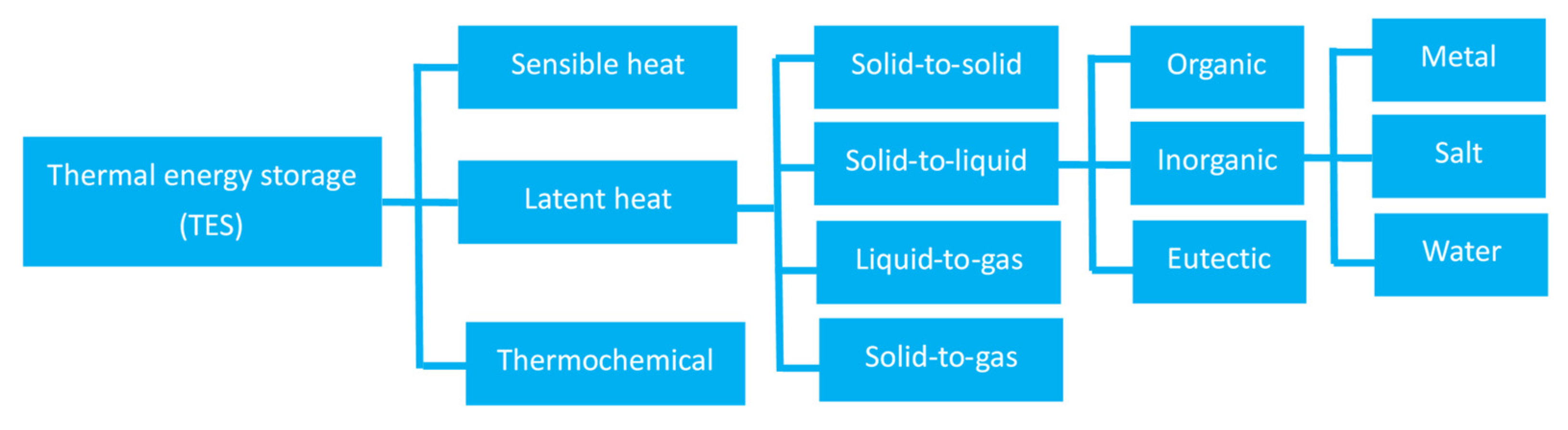
:1. Introduction
1.1. Background
1.2. Literature Review
1.3. Objective and Focus
2. Methods
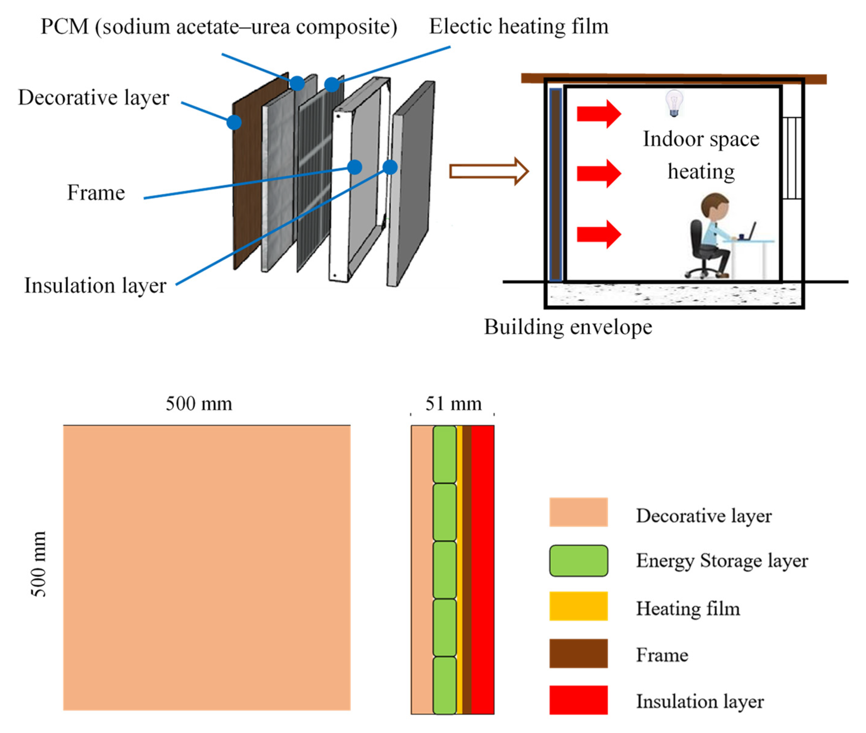
2.1. Molecular PCM Wall unit with Sodium Acetate–Urea Composite
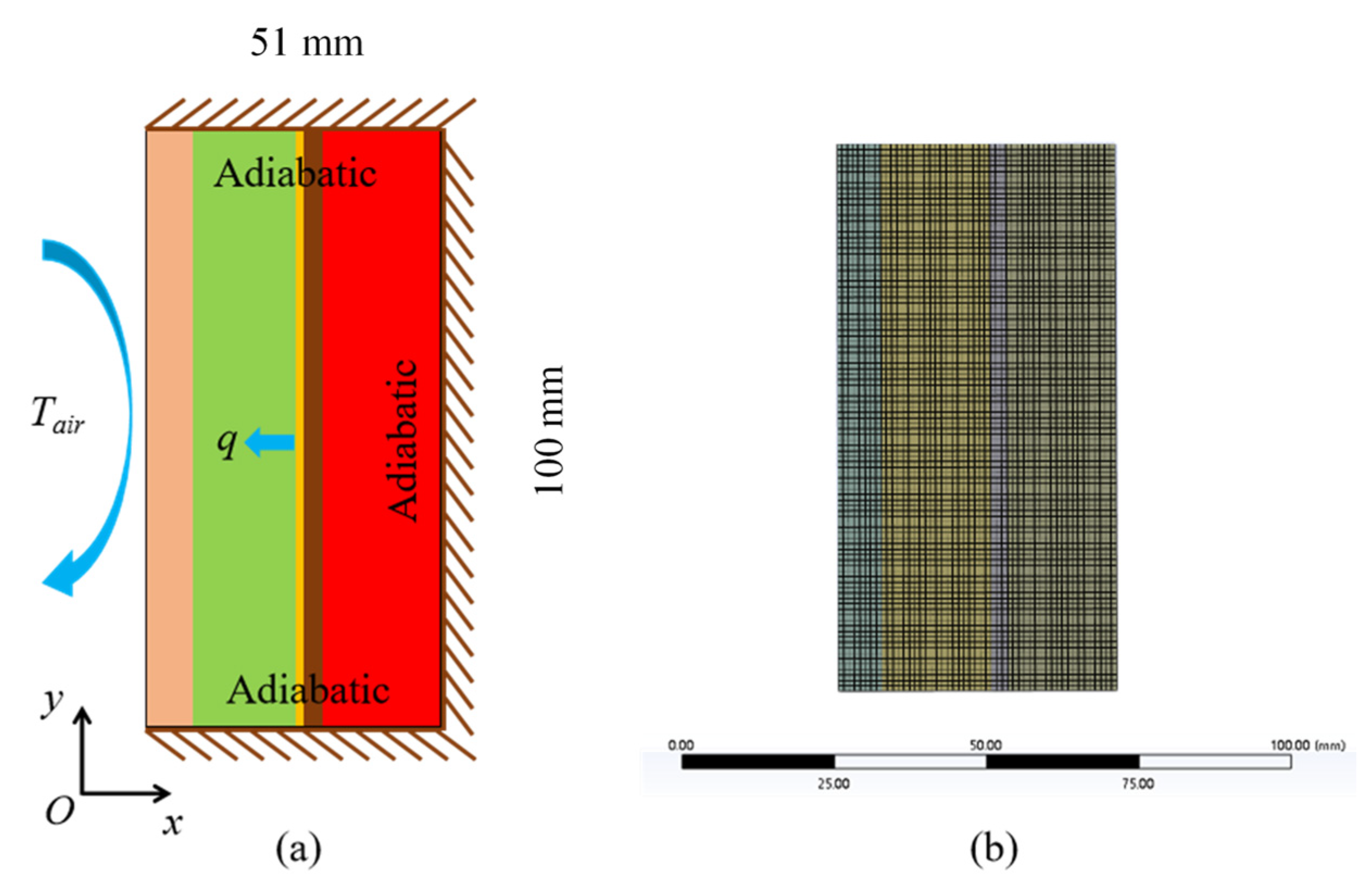
2.2. Dynamic Heat Transfer Modeling
- The motion of melted PCM is considered a Newtonian incompressible laminar flow;
- Thermophysical properties of the PCM are independent of temperature;
- Boussinesq approximation is invoked to model buoyancy-induced natural convection;
- All materials are regarded as homogeneous and isotropic in all directions;
- PCM volume change during the phase transition is negligible;
- Contact surfaces are closely fitted, the contact thermal resistance of the interface is zero, and the temperature and heat flow are continuous;
- The thickness of the electric heating film is zero.
3. Results and Discussion
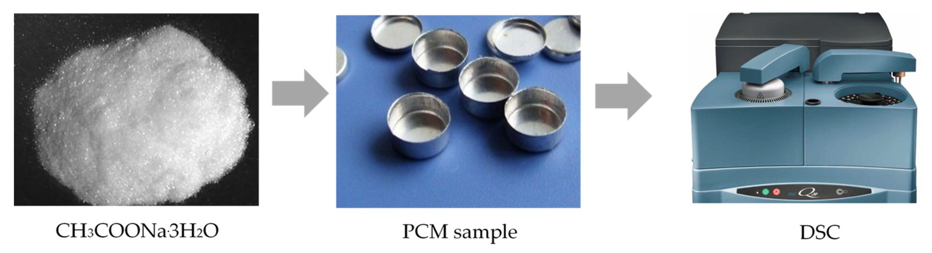
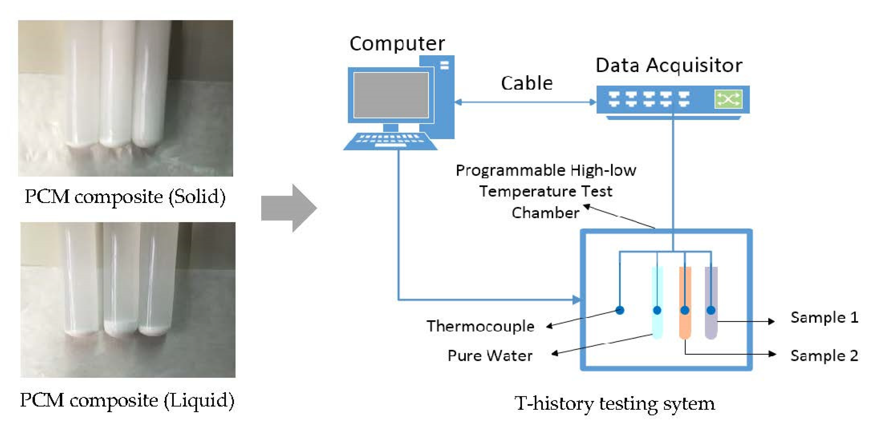
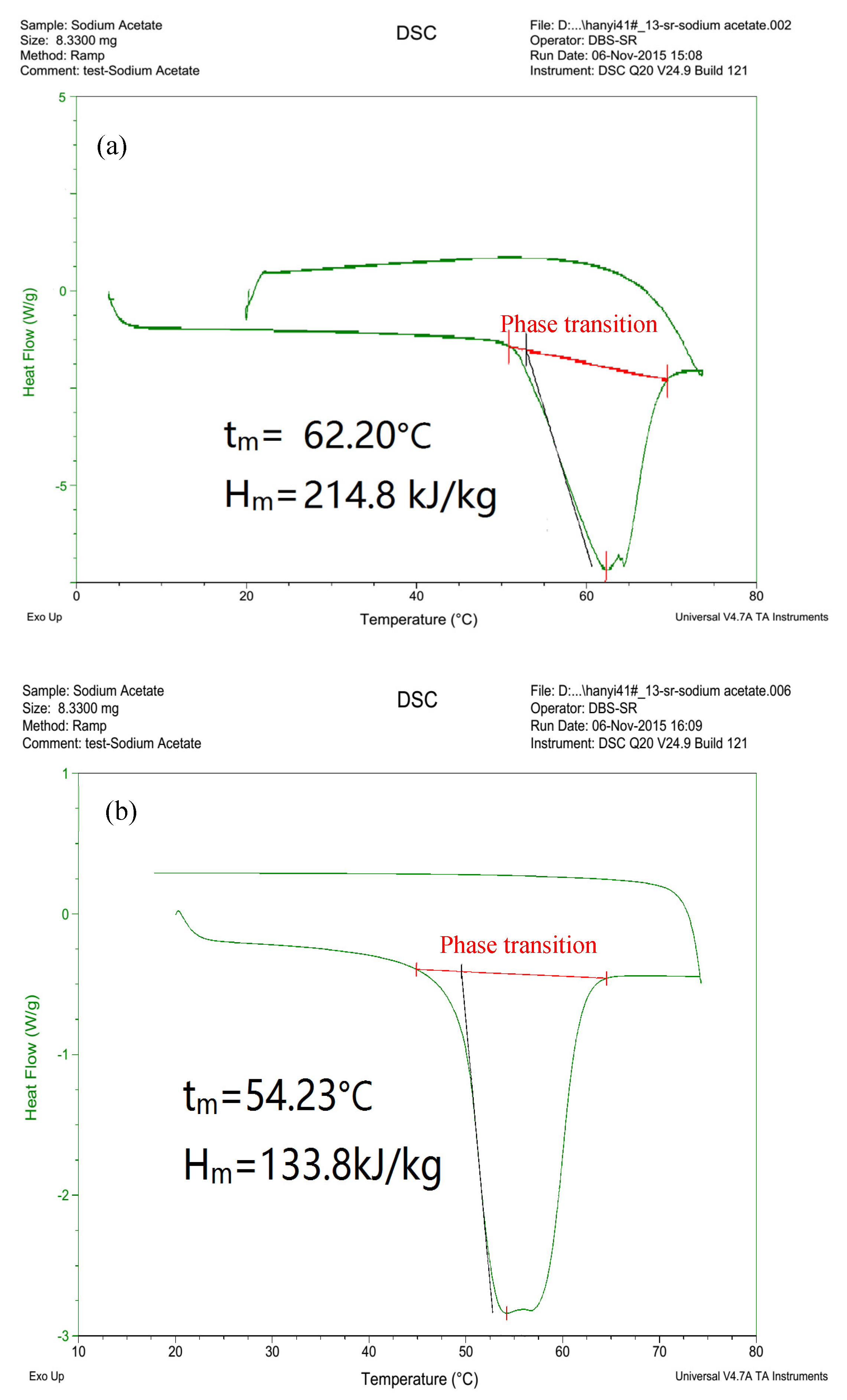
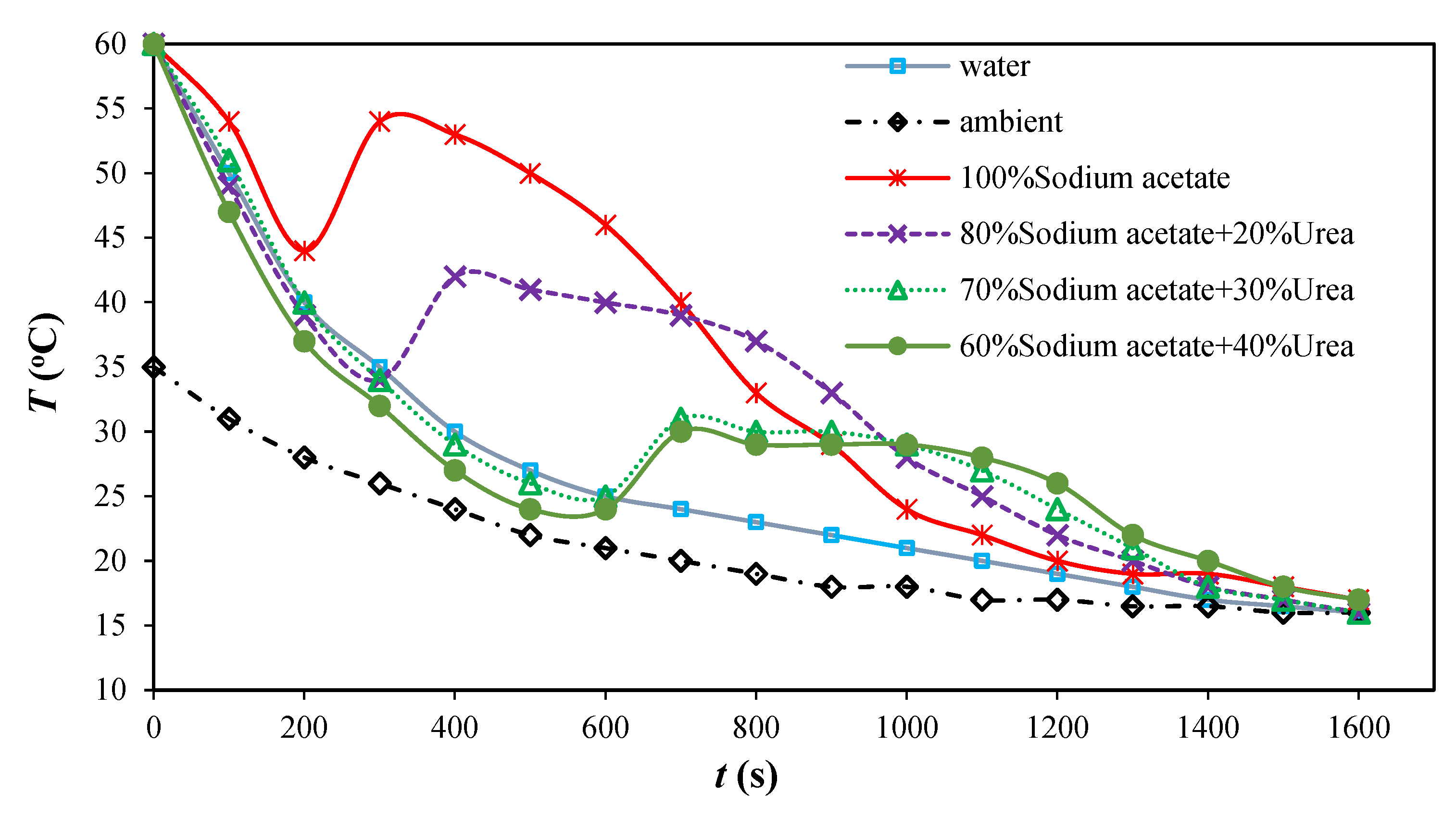
3.1. PCM Thermophysical Property Testing
3.2. Numerical Case Analysis
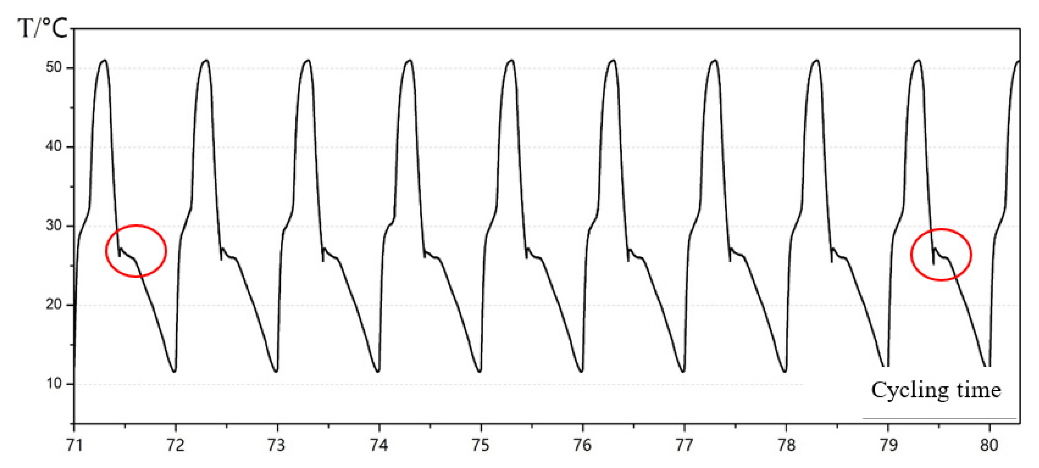
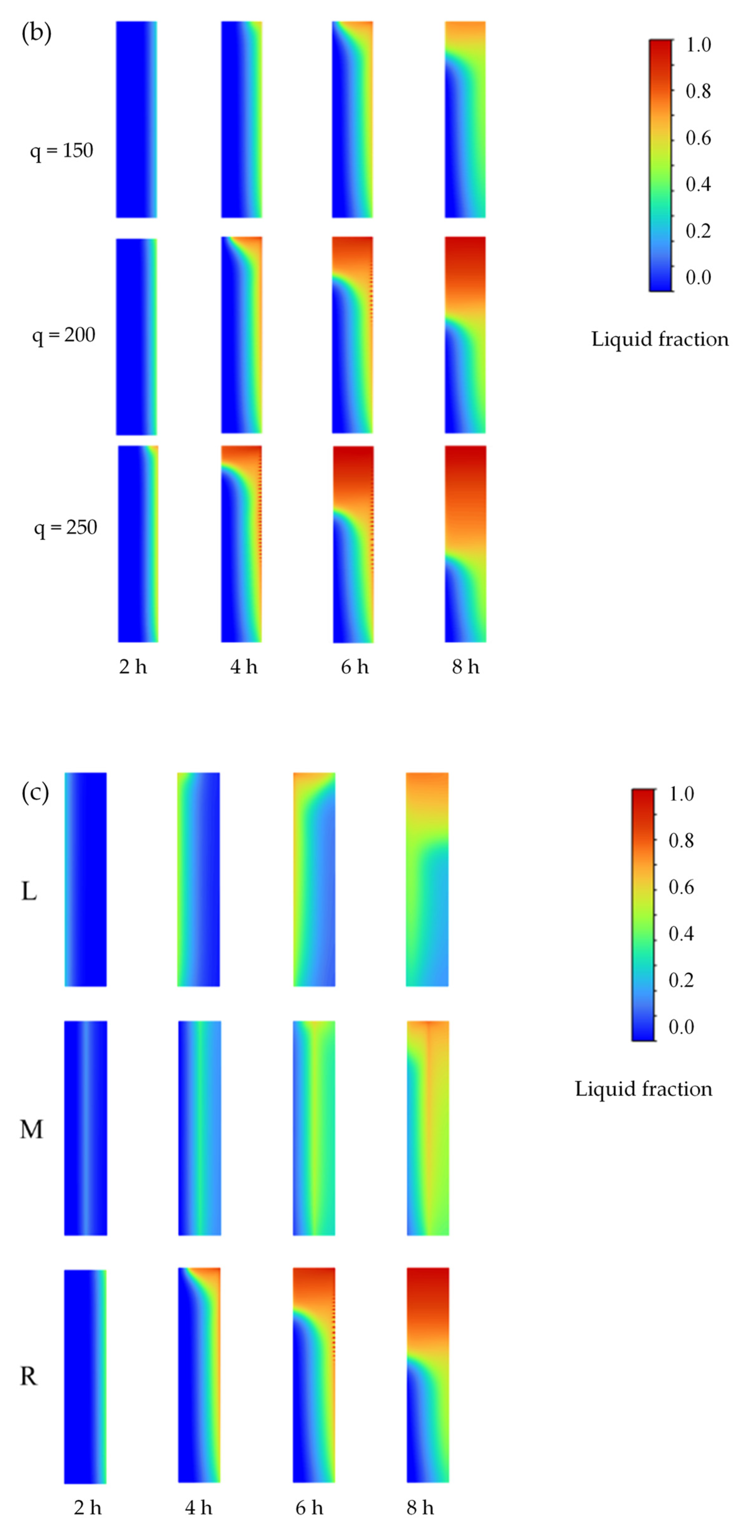
3.3. Dynamic Phase Change Simulation
4. Conclusions and Prospects
- (1)
- An increased urea fraction leads to a reduction in melting temperature. For 30% urea composite, the melting temperature ranges from 28 to 30 °C, approaching the indoor thermal comfort level, with enhanced thermal stability during cycles;
- (2)
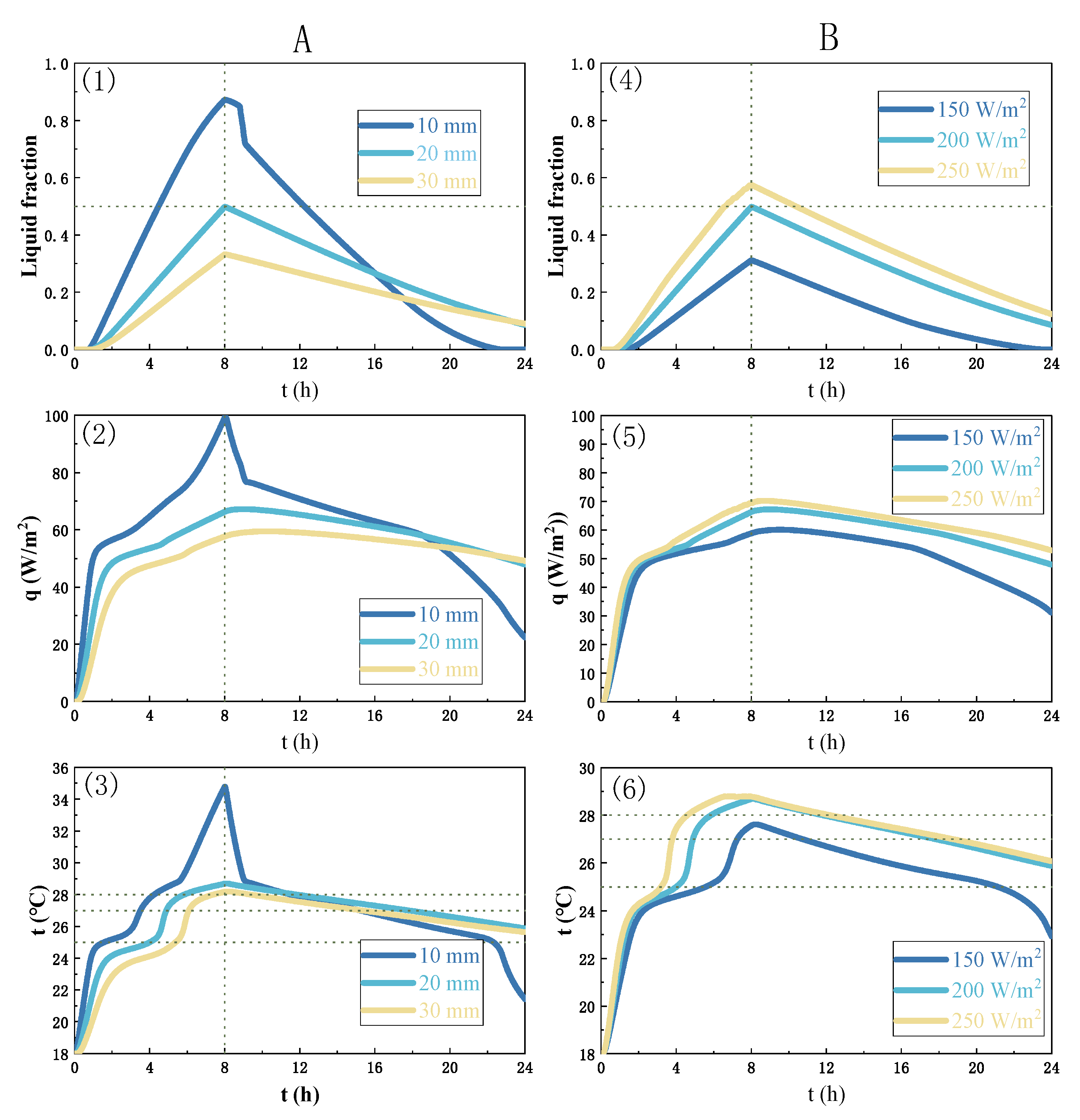
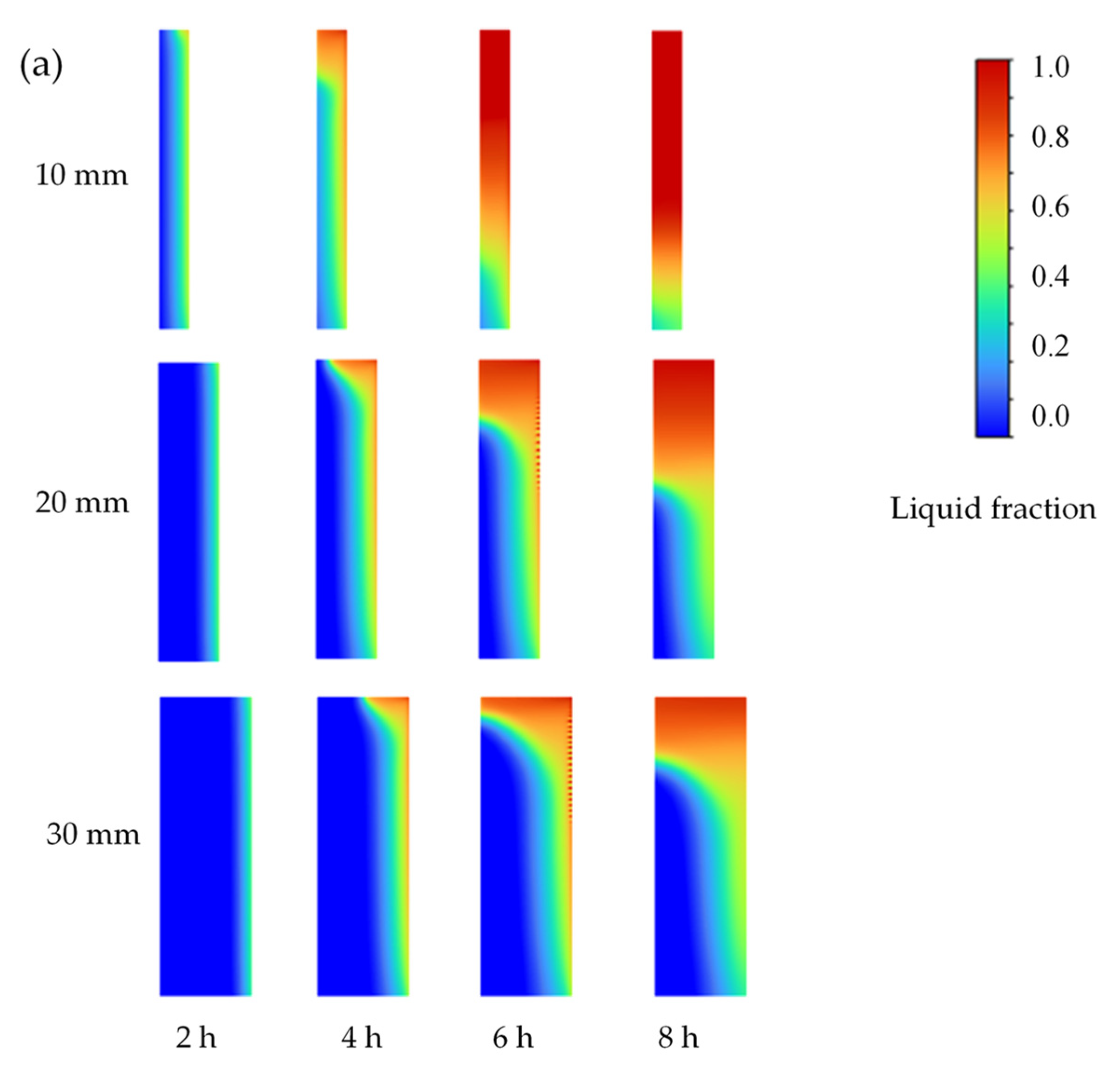
- With decreasing PCM layer thickness, the melting time is reduced, and released heat capacity increases. However, reducing the PCM layer thickness may also increase overheating risk, leading to considerable fluctuation of the heat flow and surface temperature;
- (3)
- Increased heating power contributes to increased PCM melting speed. For the studied case, a 20 mm thick PCM layer with 150 W/m2 heating power can maintain the surface temperature within the comfort range for approximately half the time in a charge–discharge cycle;
- (4)
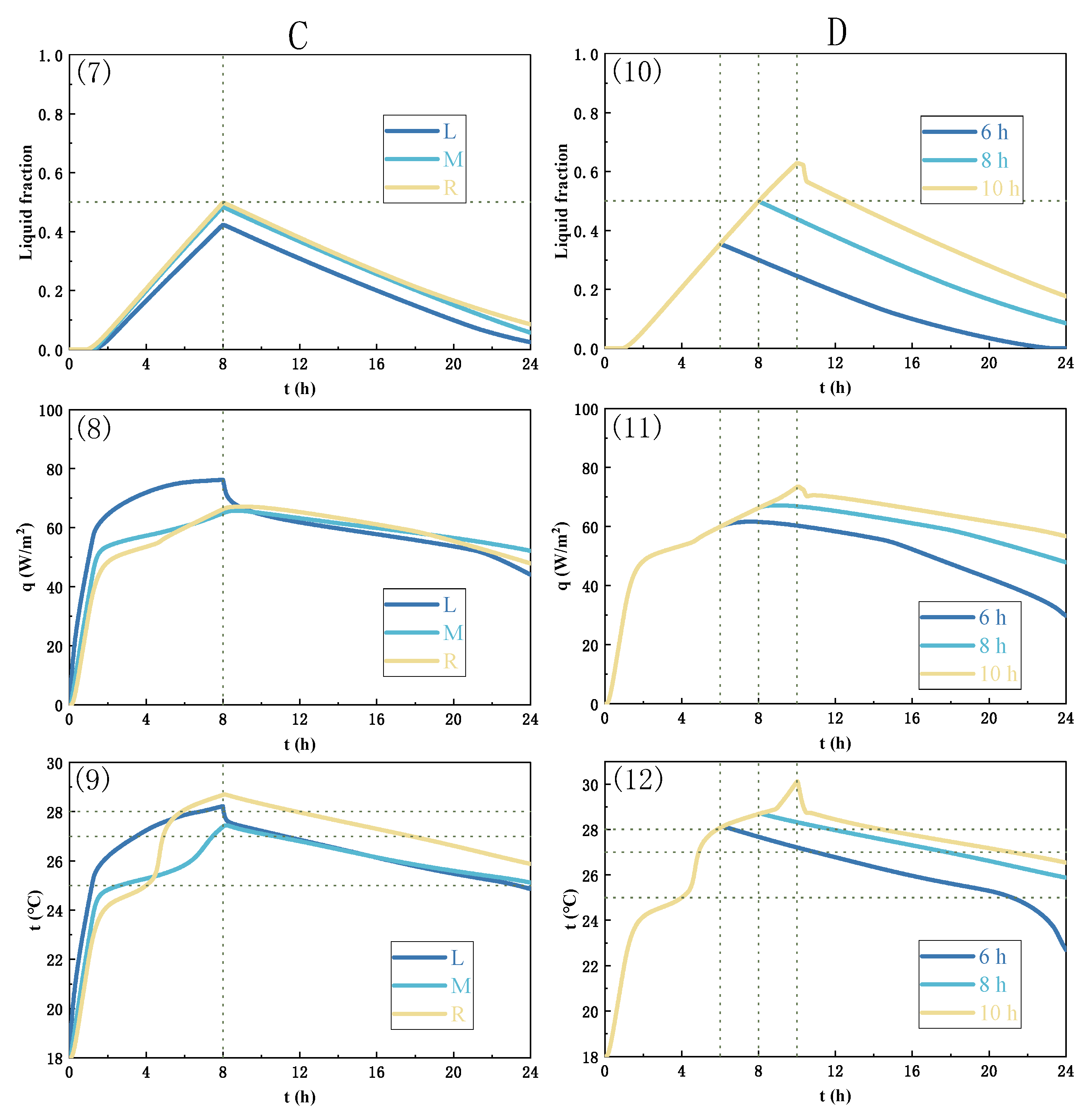
- Placing the heating film in the middle of the PCM wall unit can improve the overall heat efficiency and PCM melting uniformity, shortening the time required to reach the thermal comfort temperature range.
Author Contributions
Funding
Institutional Review Board Statement
Data Availability Statement
Conflicts of Interest
References
- Pokhrel, R.; Gonzalez, J.E.; Ramamurthy, P.; Comarazamy, D. Impact of building energy mitigation measures on future climate. Atmosphere 2023, 14, 463. [Google Scholar] [CrossRef]
- Sibill, M.; Touibi, D.; Abanda, F.H. Rethinking abandoned buildings as positive energy buildings in a former industrial site in Italy. Energies 2023, 16, 4503. [Google Scholar] [CrossRef]
- Zheng, Y.H.; Si, P.F.; Zhang, Y.; Shi, L.J.; Huang, C.J.J.; Huang, D.S.; Jin, Z.N. Study on the effect of radiant insulation panel in cavity on the thermal performance of broken-bridge aluminum window frame. Buildings 2023, 13, 58. [Google Scholar] [CrossRef]
- Xu, Z.W.; Sun, X.Y.; Li, X.F.; Wang, Z.C.; Xu, W.; Shao, S.Q.; Xu, C.; Yang, Q.; Li, H.; Zhao, W.Y. On-off cycling model featured with pattern recognition of air-to-water heat pumps. Appl. Therm. Eng. 2021, 196, 117317. [Google Scholar] [CrossRef]
- Ouyang, H.L.; Tang, X.; Kumar, R.; Zhang, R.H.; Brasseur, G.; Churchill, B.; Alam, M.; Kan, H.D.; Liao, H.; Zhu, T. Toward better and healthier air quality: Implementation of WHO 2021 global air quality guidelines in Asia. Bull. Am. Meteorol. Soc. 2022, 103, 1696–1703. [Google Scholar] [CrossRef]
- Xu, Z.W.; Li, H.; Shao, S.Q.; Xu, W.; Wang, Z.C.; Wang, Y.C.; Sun, X.Y.; Yang, Q.; Xu, C.; Zhao, Y.W. A semi-theoretical model for energy efficiency assessment of air source heat pump systems. Energy Convers. Manag. 2021, 228, 113667. [Google Scholar] [CrossRef]
- Qi, X.Y.; Zhang, Y.; Jin, Z.N. Building energy efficiency for indoor heating temperature set-point: Mechanism and case study of mid-rise apartment. Buildings 2023, 13, 1189. [Google Scholar] [CrossRef]
- Yan, Z.; Zhang, Y.; Liang, R.; Jin, W. An allocative method of hybrid electrical and thermal energy storage capacity for load shifting based on seasonal difference in district energy planning. Energy 2020, 207, 118139. [Google Scholar] [CrossRef]
- Li, Y.R.; Long, E.S.; Jin, Z.H.; Li, J.; Meng, X.; Zhou, J.; Xu, L.T.; Xiao, D.T. Heat storage and release characteristics of composite phase change wall under different intermittent heating conditions. Sci. Technol. Built Environ. 2019, 25, 336–345. [Google Scholar] [CrossRef]
- Ding, P.; Li, J.; Xiang, M.L.; Cheng, Z.; Long, E.S. Dynamic heat transfer calculation for ground-coupled floor in emergency temporary housing. Appl. Sci. 2022, 12, 11844. [Google Scholar] [CrossRef]
- Wi, S.; Yang, S.; Park, J.H.; Chang, S.J.; Kim, S. Climatic cycling assessment of red clay/perlite and vermiculite composite PCM for improving thermal inertia in buildings. Build. Environ. 2020, 167, 106464. [Google Scholar]
- Xu, Z.; Chen, Y.; Lin, P.; Zhu, X. Leakproof phase-change glass window: Characteristics and performance. Build. Environ. 2022, 218, 109088. [Google Scholar] [CrossRef]
- Prabakaran, R.; Dhamodharan, P.; Sathishkumar, A.; Gullo, P.; Vikram, M.P.; Pandiaraj, S.; Alodhayb, A.; Khouqeer, G.A.; Kim, S.C. An overview of the state of the art and challenges in the use of gelling and thickening agents to create stable thermal energy storage materials. Energies 2023, 16, 3306. [Google Scholar] [CrossRef]
- Zeng, R.L.; Wang, X.; Di, H.F.; Zhang, Y.P. New concept and approach for developing energy efficient buildings: Ideal specific heat for building internal thermal mass. Energy Build. 2011, 43, 1081–1090. [Google Scholar] [CrossRef]
- Kitagawa, H.; Asawa, T.; Kubota, T.; Trihamdani, A.R.; Mori, H. Thermal storage effect of radiant floor cooling system using phase change materials in the hot and humid climate of Indonesia. Build. Environ. 2022, 207, 108442. [Google Scholar] [CrossRef]
- Gonzalez, B.; Prieto, M.M. Radiant heating floors with PCM bands for thermal energy storage: A numerical analysis. Int. J. Therm. Sci. 2021, 162, 106803. [Google Scholar] [CrossRef]
- Zhang, Y.; Wang, X.; Wei, Z.Y.; Zhang, Y.P.; Feng, Y. Sodium acetate–urea composite phase change material used in building envelopes for thermal insulation. Build. Serv. Eng. Res. Technol. 2018, 39, 475–491. [Google Scholar] [CrossRef]
- Li, J.; Zhang, Y.; Ding, P.; Long, E.S. Experimental and simulated optimization study on dynamic heat discharge performance of multi-units water tank with PCM. Indoor Built Environ. 2021, 30, 1531–1545. [Google Scholar] [CrossRef]
- Cheng, R.; Pomianowski, M.; Wang, X.; Zhang, Y.P. A new method to determine thermophysical properties of PCM-concrete brick. Appl. Energy 2014, 112, 988–998. [Google Scholar] [CrossRef]
- ANSI/ASHRAE 169-2013; Climatic Data for Building Design Standards. American Society of Heating, Refrigerating, and Air-Conditioning Engineers, Inc.: Atlanta, GA, USA, 2013.
- Guo, J.; Dong, J.; Wang, H.; Jiang, Y.; Tao, J. On-site measurement of the thermal performance of a novel ventilated thermal storage heating floor in a nearly zero energy building. Build. Environ. 2021, 201, 107993. [Google Scholar] [CrossRef]
- Munoz, P.; Dominguez, D.; Morales, M.P.; Munoz, L.; Sanchez-Vazquez, R. The effect of infill walls made by eco materials on mechanical response, energy performance and CO2 print of residential and non-residential low-rise buildings. Energy Build. 2021, 243, 110996. [Google Scholar] [CrossRef]
- Jin, Z.N.; Zheng, Y.H.; Zhang, Y. A novel method for building air conditioning energy saving potential pre-estimation based on thermodynamic perfection index for space cooling. J. Asian Archit. Build. Eng. 2023, 22, 2348–2364. [Google Scholar] [CrossRef]
- Letelier, V.; Bustamante, M.; Munoz, P.; Rivas, S.; Ortega, J.M. Evaluation of mortars with combined use of fine recycled aggregates and waste crumb rubber. J. Build. Eng. 2021, 43, 103226. [Google Scholar] [CrossRef]
- Prabakaran, R.; Salman, M.; Kumar, P.G.; Lee, D.; Kim, S.C. Heat transfer and pressure drop characteristics of R1234yf during evaporation in a plate heat exchanger with offset strip fins: An experimental study. Int. J. Heat Mass Transf. 2022, 194, 123091. [Google Scholar] [CrossRef]
- Kim, S.C.; Prabakaran, R.; Sakthivadivel, D.; Thangapandian, N.; Bhatia, A.; Kumar, P.G. Thermal transport properties of carbon-assisted phase change nanocomposite. Fuller. Nanotub. Carbon Nanostructures 2020, 28, 925–933. [Google Scholar] [CrossRef]
- Kumar, P.G.; Prabakaran, R.; Sakthivadivel, D.; Thangapandian, N.; Velraj, R.; Kim, S.C. Effect of shot blasting on droplet contact angle of carbon aided phase change nanocomposites. Surf. Eng. 2021, 37, 1002–1011. [Google Scholar] [CrossRef]
- Zhang, Y.P.; Jiang, Y.; Jiang, Y. A simple method, the T-history method, of determining the heat of fusion, specific heat and thermal conductivity of phase change materials. Meas. Sci. Technol. 1999, 10, 201–205. [Google Scholar]
- Zhou, Y.K.; Liu, Z.X.; Zheng, S.Q. 15—Influence of novel PCM-based strategies on building cooling performance. In Eco-Efficient Materials for Reducing Cooling Needs in Buildings and Construction; Woodhead Publishing Series in Civil and Structural Engineering; Woodhead Publishing: Sawston, UK, 2021; pp. 329–353. [Google Scholar]
- Munoz, P.; Dominguez, D.; Sanchez-Vazquez, R.; Letelier, V.; Gencel, O. Building decarbonization by means of ancient techniques. Assessment of environmental impact, energy performance and mechanical safety. J. Build. Eng. 2023, 74, 106896. [Google Scholar] [CrossRef]
- Jin, X.; Xiao, Q.K.; Xu, T.; Huang, G.S.; Wu, H.J.; Wang, D.J.; Liu, Y.F.; Zhang, H.G.; Lai, C.K. Thermal conductivity enhancement of a sodium acetate trihydrate-potassium chloride-urea/expanded graphite composite phase-change material for latent heat thermal energy storage. Energy Build. 2021, 231, 110615. [Google Scholar] [CrossRef]
- Sun, W.C.; Liang, G.H.; Feng, F.L.; He, H.M.; Gao, Z.M. Study on sodium acetate trihydrate-expand graphite-carbon nanotubes composite phase change materials with enhanced thermal conductivity for waste heat recovery. J. Energy Storage 2022, 55, 105857. [Google Scholar] [CrossRef]
- Ho, C.J.; Chang, P.C.; Yan, W.M.; Amani, M. Microencapsulated n-eicosane PCM suspensions: Thermophysical properties measurement and modeling. Int. J. Heat Mass Transf. 2018, 125, 792–800. [Google Scholar] [CrossRef]
- ANSI/ASHRAE 55-2020; Thermal Environmental Conditions for Human Occupancy. American Society of Heating, Refrigerating, and Air-Conditioning Engineers, Inc.: Atlanta, GA, USA, 2020.


| PCM | Melting Temperature Tm (°C) | Enthalpy Hm (kJ/kg) | |
|---|---|---|---|
| Organic | Paraffin | 25–30 | 150 |
| Butyl stearate CH3(CH2)16COO(CH2)3CH3 | 18–23 | 140 | |
| N-octadecane CH3(CH2)16CH3 | 22.5–26.2 | 205 | |
| Dodecanol CH3(CH2)11OH | 17.5–23.3 | 188 | |
| Inorganic | Potassium fluoride KF·4H2O | 18.5–19 | 231 |
| Calcium chloride CaCl2· | 29.7 | 171 | |
| Sodium sulphite Na2S2O3· | 40 | 210 | |
| Sodium acetate CH3COONa | 45–55 | 240 |
| Layer | Decoration | PCM | Frame | Insulation |
|---|---|---|---|---|
| Material | Wood fiber | Sodium acetate–urea | Nanomontmorillonite fiber composites | Extruded polystyrene |
| Thickness (mm) | 8 | 20 | 3 | 20 |
| Solid/liquid density, ρ (kg/m3) | 1000 | 1460/1480 | 2000 | 35 |
| Thermal solid/liquid conductivity, k (W/m·K) | 0.34 | 1.2/0.56 | 2002.5 | 1380 |
| Specific solid/liquid heat capacity, cp (J/kg·K) | 2510 | 2410/2720 | 0.45 | 0.03 |
| Thermal expansion coefficient, β (1/K) | 0.00044 | |||
| Dynamic viscosity, μ (Pa·s) | 0.00324 | |||
| Melting point, Tm (K) | 301.15–305.15 | |||
| Latent heat, hsf (kJ/kg) | 200 |
| Group | Case | d (mm) | q (W/m2) | Position | tcharge/tdischarge |
|---|---|---|---|---|---|
| A | 1 | 10 | 200 | R | 8/16 |
| 2 | 20 | 200 | R | 8/16 | |
| 3 | 30 | 200 | R | 8/16 | |
| B | 4 | 20 | 150 | R | 8/16 |
| 5 | 20 | 200 | R | 8/16 | |
| 6 | 20 | 250 | R | 8/16 | |
| C | 7 | 20 | 200 | L | 8/16 |
| 8 | 20 | 200 | M | 8/16 | |
| 9 | 20 | 200 | R | 8/16 | |
| D | 10 | 20 | 200 | L | 6/18 |
| 11 | 20 | 200 | M | 8/16 | |
| 12 | 20 | 200 | R | 10/14 |
Disclaimer/Publisher’s Note: The statements, opinions and data contained in all publications are solely those of the individual author(s) and contributor(s) and not of MDPI and/or the editor(s). MDPI and/or the editor(s) disclaim responsibility for any injury to people or property resulting from any ideas, methods, instructions or products referred to in the content. |
© 2023 by the authors. Licensee MDPI, Basel, Switzerland. This article is an open access article distributed under the terms and conditions of the Creative Commons Attribution (CC BY) license (https://creativecommons.org/licenses/by/4.0/).
Share and Cite
Yang, Q.; Xiong, J.; Mao, G.; Zhang, Y. A Novel Molecular PCM Wall with Inorganic Composite: Dynamic Thermal Analysis and Optimization in Charge–Discharge Cycles. Materials 2023, 16, 5955. https://doi.org/10.3390/ma16175955
Yang Q, Xiong J, Mao G, Zhang Y. A Novel Molecular PCM Wall with Inorganic Composite: Dynamic Thermal Analysis and Optimization in Charge–Discharge Cycles. Materials. 2023; 16(17):5955. https://doi.org/10.3390/ma16175955
Chicago/Turabian StyleYang, Qianru, Jianwu Xiong, Gang Mao, and Yin Zhang. 2023. "A Novel Molecular PCM Wall with Inorganic Composite: Dynamic Thermal Analysis and Optimization in Charge–Discharge Cycles" Materials 16, no. 17: 5955. https://doi.org/10.3390/ma16175955