Article

Effect of C Addition on the Microstructure and Fracture Properties of In Situ Laminated Nb/Nb5Si3 Composites

1
School of Materials Science and Engineering, Central South University, Changsha 410083, China
2
Key Laboratory of Non-Ferrous Metal Materials Science and Engineering, Ministry of Education, Central South University, Changsha 410083, China
3
Powder Metallurgy Research Institute, Central South University, Changsha 410083, China
*
Author to whom correspondence should be addressed.
Materials 2023, 16(16), 5637; https://doi.org/10.3390/ma16165637
Submission received: 8 June 2023 / Revised: 26 July 2023 / Accepted: 1 August 2023 / Published: 15 August 2023
(This article belongs to the Special Issue Phase and Structure Analysis of Alloys and Metal Matrix Composites)

Abstract

:
//Nbss and α-Nb5Si3 phases were detected. Meanwhile, Nb2C was observed, and the crystal forms of Nb5Si3 changed in the C-doped composites. Furthermore, micron-sized and nano-sized Nb2C particles were found in the Nbss layer. The orientation relationship of Nb2C phase and the surrounding Nbss was [001]Nbss//[010]Nb2C, (200) Nbss//(101) Nb2C. Additionally, with the addition of C, the compressive strength of the composites, at 1400 °C, and the fracture toughness increased from 310 MPa and 11.9 MPa·m1/2 to 330 MPa and 14.2 MPa·m1/2, respectively; the addition of C mainly resulted in solid solution strengthening.

1. Introduction

The Nb5Si3 intermetallic compound has been considered as a potential material for high-performance structural application due to its high melting point (2520 °C), low density (7.1 g/cm3), and excellent strength retention at elevated temperatures [1,2,3]. However, due to the relatively low fracture toughness of 1–3 MPa·m1/2 at ambient temperatures [4], a ductile niobium-based solid solution (Nbss) was brought into Nb5Si3 to achieve a balance of low fracture toughness and high temperature strength [5,6,7,8,9,10,11,12]. As for the as-cast Nb-Si alloy, with the increase in Si content, the volume fraction of ductile Nbss phase decreased, thereby significantly lowering the fracture toughness [13,14]. It was reported that the fracture toughness of Nb-10Si and Nb-16Si alloys were 12 MPa·m1/2 and 4.5 MPa·m1/2, respectively [15]. In order to improve the fracture toughness of Nb-Si alloys, a number of reinforcement elements such as Ti, Mo, and B were added as well [16,17]. Wang et al. [18] reported that the fracture toughness of Nb-16Si alloy improved after increasing the Hf content. Furthermore, the addition of B could also enhance the fracture toughness of a Nb-10W-10Si alloy [19].
Preparing unidirectionally solidified alloys and laminated composites has also been shown to be an efficient method of enhancing fracture toughness. Ye et al. [20] found that excellent fracture toughness of 14.5 MPa·m1/2 and 18.7 MPa·m1/2 could be exhibited by unidirectionally solidified Nb-Si and Nb-Si-Ti alloys, respectively. A Nb5Si3/Nb/Nb5Si3 laminate with a relatively high fracture toughness of 7.1–11.5 MPa·m1/2 was fabricated by hot pressing the Nb5Si3 compacts and Nb foil at 1200 °C for 5 h [21]. However, since the thickness of the Nb5Si3 compacts and Nb foil were 4 mm and 0.25 mm, respectively, the fracture toughness apparently changed into the distance changes of notch from the Nb/Nb5Si3 interface. Thus, the thickness of Nbss and Nb5Si3 layers should be decreased, and the in situ laminated Nb/Nb5Si3 composite with micron-sized multi-layer structures was fabricated from the previous work [22].
Furthermore, it was reported that the Nb-16Si-10Mo-15W alloy could be strengthened by addition a solution to B in the Nb5Si3 phases [23,24,25]. Similarly, it was confirmed that a C atom could also dissolve in the Nb3Al phase [26,27,28]. Due to fact that the C atom has a smaller radius than the B atom, the strengthening effect of adding a solid solution to C in the Nb5Si3 would be probably better than that of B. Reports regarding the addition of C to a Nb/Nb5Si3 alloy are scarce in the open literature. It is unclear whether and to what extent the addition of C can improve the fracture toughness of a Nb/Nb5Si3 alloy. Therefore, the aim of this work was to prepare in situ laminated Nb/Nb5Si3 composites supplemented with C via spark plasma sintering, evaluate the effect of C on the microstructure and mechanical properties of the composites, and identify the strengthening and toughening mechanisms.

2. Experimental Procedure

Nb foils (99.99%, 25 μm in thickness), Nb powders (99.99%, 1–3 μm), Si powders (99.99%, 1–3 μm), and C powders (99.99%, 1–3 μm) were the raw materials used. For the experimental work, a three-step procedure was adopted. Firstly, mixtures of molar ratios of Nb-50Si and Nb-40Si-10C were selected to prepare the Nb/Si/(C) slurry via vacuum ball milling for 24 h using ethanol as a milling medium. For convenience of expression, the corresponding prepared materials are called Nb-50Si and Nb-40Si-10C, respectively. Secondly, the Nb foils were covered with mixed Nb/Si/(C) slurry via the dip-coating method and then stacked together and dried at 120 °C for 24 h in a vacuum. Thirdly, the stacked Nb foils were put in a graphite die and sintered at 1750 °C under a pressure of 30 MPa for 30 min in vacuum using a heating rate of 100 °C/min. Finally, the sintered Nb/Nb5Si3 composites were cooled at about a rate of 100 °C/min above 500 °C and then furnace-cooled down to room temperature. A diagram of the preparation process for the niobium-based composites is shown in Figure 1. The sintered material had a porosity of 0.3381% and a density of 8.1621 g/cm3.
The phase and crystallinity were analyzed via X-ray diffraction (XRD) using CuKα radiation at 40 kV and 250 mA. The lattice parameters were calculated by using JADE 5 software. The microstructures of the samples were characterized using scanning electron microscopy (SEM), wavelength-dispersive spectroscopy (WDS), and transmission electron microscopy (TEM). The SEM samples were cut via electrical discharge machining (EDM) and polished to a surface finish using 1 μm diamond paste, and the TEM foils were prepared via ion milling. The volume fractions of phase in the composite were calculated via quantitative image analysis using EPMA micrographs; five EPMA images were used for each composite. Fracture toughness was determined via three-point bending (TPB) tests at room temperature. In the TPB tests, a specimen with a dimension of 2.5 mm × 5 mm × 20 mm and a notch introduced perpendicular to the layer direction was cut via electro-discharge machining (EDM), and the cross-head speed was set at a rate of 0.1 mm/min. Compression tests were conducted at 1400 °C at a strain rate of 10−3 s−1 in a vacuum. The dimension of the compression test specimen was φ4 mm × 6 mm, and the loading direction was parallel to the layer direction. Five specimens were tested for each condition, and the average values were recorded. A computer microhardness tester (200HBVS-30) was used to measure the Vickers hardness of the alloy under a load of 15 N, and the test time was 15 s. The same alloy sample was tested 5 times at random locations; a group of 3 samples were tested, and the average value of each measurement was taken as the Vickers hardness of the alloy.

3. Results and Discussion

Figure 2 shows XRD patterns of the Nb-50Si and Nb-40Si-10C composites. It was found that the obtained Nb-50Si composite exhibited an XRD pattern typical of Nbss and α-Nb5Si3. However, following the addition of C, Nb2C and γ-Nb5Si3 were present in the Nb-40Si-10C composite. This indicated that the addition of C promoted the formation of the metastable γ-Nb5Si3 phase and high temperature β-Nb5Si3 phase. Additionally, it should be pointed out that SiC was not identified in the patterns. The PDF card numbers of the phases involved in the Figure 1 are shown in Table 1.
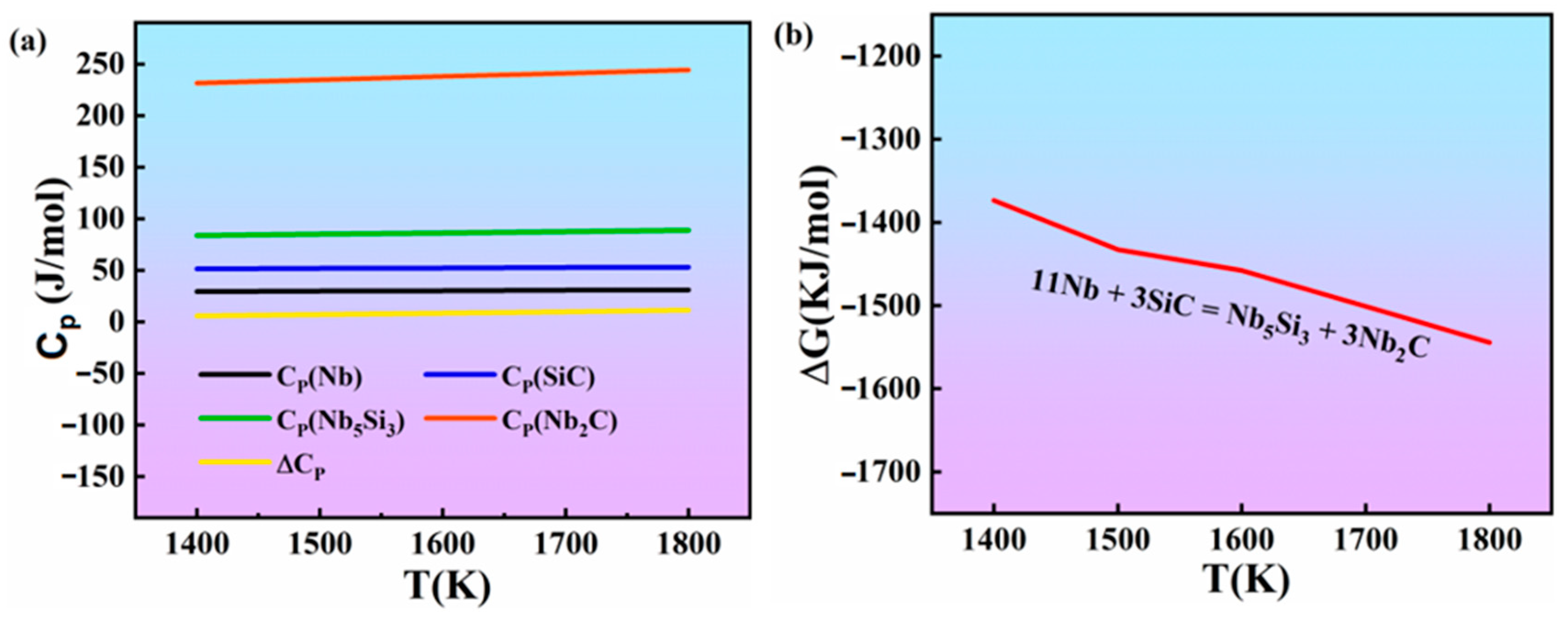
It was assumed that little SiC remained in the material. The following reaction was induced:
11Nb + 3SiC = Nb5Si3 + 3Nb2C
The thermodynamic results of reaction (1) are listed in the following reaction (reaction (2)) according to the thermodynamic data shown in Table 2.
H 298 Θ = 817,134   J             S 298 Θ   =   393.255   J · K 1
The standard Gibbs free energy of reaction (1) can be expressed as (3), according to the calculation of the second approximation equation of thermodynamics:
G T Θ = H 298 Θ S 298 Θ + C P T   ( l n 298 T + 1 298 T )
The molar heat capacities of the various substances in reaction (1) at 1400–1800 K and the standard Gibbs free energy at different temperatures is shown in Figure 3. As shown in Figure 3, with increasing temperature, the standard Gibbs free energy of the reaction (1) decreased, and all the values were negative. Therefore, according to the above results, reaction (1) occurred during the sintering process. Therefore, all of the XRD patterns show the absence of SiC in the Nb/Nb5Si3 composites.
Figure 4 shows the microstructures of the composites. Through WDS, alternately distributed Nbss layers (point 1 in Table 3) and niobium compound layers can be observed. In the Nb-50Si composite, the average thicknesses of the Nbss layers were decreased from 25 μm to 12.7 μm with increasing sintering time, confirm Si element diffusion from the Nb5Si3 layers (point 2 in Table 3) to the Nbss layers during sintering. Interestingly, with the addition of C, we observed that the microstructures of the composites significantly changed. According to the WDS results shown in Table 3, the Nb2C particle (3–5 μm) was present in the Nbss layers and exhibited a morphology different from the carbide in as-cast Nb-20Ti-12.5C-Mo-Hf alloys [29]. In addition, a lot of fine carbide (nano-sized) was also observed in the Nbss layer. The formation mechanism of the carbide will be discussed later. Secondly, both C-rich (point 4) and C-poor (point 3) Nb5Si3 were observed in the compound layers, which can be attributed to the different diffusion rates of the Si and C atoms in Nb. Due to the lighter atomic mass and smaller atomic radius of C compared to Si, the diffusion rate of C should be higher than Si, leading to the longer diffusion distance of the C element. As a result, the C-rich Nb5Si3 is closer to the Nbss layers. A relatively high oxygen content of 1.3 wt% was detected in the Nbss layer of the Nb-50Si composite. This was due to the fact that the dipping and stacking of the Nb foils was preformed in the air. Due to the fine Nb and Si powders, it is very difficult to avoid the physisorption of oxygen during the synthesis of the composites. However, interestingly, we observed that the O content (point 5) in the Nbss layer decreased to 0.3 wt.% in the Nb-40Si-10C composite.
Figure 4. Microstructure of alloys: (a) Nb-50Si alloy; (b) Nb-40Si-10C alloy. Points 1–7 refer to the WDS punctual analysis summarized in Table 4.
Materials 16 05637 g004
The decrease in oxygen content can be explained via thermodynamic calculation. It is assumed that NbO exists in the material, and the following reactions can be assumed:
NbO + C = Nb + CO
According to the relevant thermodynamic constants in Table 4, the thermodynamic calculation of reaction (4) is as follows:
H 298 Θ = 298,236   J           S 298 Θ   = 177.988   J · K 1
Figure 5a shows the molar constant pressure heat capacities of the various substances in reaction (4) in the range of 1400–2000 K, which were calculated according to the second approximate equation of thermodynamics and allows one to obtain the standard Gibbs free energy of reaction (4) at different temperatures.
As can be seen from Figure 5b, with increasing temperature, the standard Gibbs free energy of the reaction decreases. When the temperature reaches 1900 K (~1627 °C), the standard Gibbs free energy is negative. As the sintering temperature of the alloy is higher than 1750 °C, reaction (4) can proceed smoothly with the sintering process, according to the above thermodynamic calculation results.
Figure 6 shows typical SEM micrographs from the fracture surfaces of sintered composites after the TPB tests. It can be seen from Figure 6a that the fracture surface of the Nb-50Si composite basically exhibited an intergranular fracture mode in conjunction with some cleavage fracture features in the Nb5Si3 layer. Meanwhile, transgranular cracking and some ridge-like features were observed in the Nbss layer. However, more transgranular cracking and some ridge-like features were observed due to the presence of the brittle Nb2C phase. This proved that the addition of C changed the fracture mechanisms of the composites. Additionally, regarding the Nb-40Si-10C composite (Figure 6b), partial dimples were observed in the Nbss layer.
In order to investigate the formation mechanisms of the Nb2C phase in the Nbss layer, the order of the reactions in the sintering layer was evaluated via thermodynamic calculation. As can be seen from Figure 4, three elements, namely Nb, Si, and C, were observed in the sintering layers. Furthermore, the C atoms tended to spread throughout the Nbss layers. Hence, what needs to be confirmed is whether the following two reactions occurred during the sintering process:
15Nb2C + 18Si = 6Nb5Si3 + 15C
Nb2C + 4Si = 2NbSi2 + C
According to the thermodynamic constants shown in Table 5, thermodynamic reactions (6) and (7) can be calculated as follows:
H 298 Θ ( 6 ) = 298,236   J           S 298 Θ ( 6 )   =   293.091   J · K 1
H 298 Θ ( 7 )   = 81,170   J           S 298 Θ ( 7 ) = 6.151   J · K 1
The molar heat capacity  C P  of the various substances at 1000–1600 K are shown in Figure 7. Therefore, the standard Gibbs free energy  G T Θ  in reactions (6) and (7) at different temperatures could be obtained by using the second approximation equation of thermodynamics. It can be seen from Table 5 that, when the temperature was above 1000 K, the standard Gibbs free energy in reactions (6) and (7) decreased with increasing temperature. Furthermore, all of the values of the standard Gibbs free energy shown in Figure 7 are negative. This proves that reactions (6) and (7) could occur during the sintering process. In other words, even though Nb2C remained in the compound layers, it can react with Si and enter into C. It was indicated that a part of the carbon in the solid solution of Nb5Si3 and the others diffuses into the Nbss layers and then reacts with Nb, forming Nb2C.
Figure 8 shows TEM micrographs typical of Nb/Nb5Si3 composites. A large number of dislocations and other defects in the Nb foils are noted in Figure 8a. Figure 8b presents the region’s selection in Figure 8a, which is about 500 nm in diameter. The polycrystalline rings can be observed in Figure 8b, which indicates that there are multiple grains in this region. Therefore, it can be suggested that the grain size of raw Nb foil is below 500 nm and that there are many grain boundaries in the raw Nb foil, providing a channel for the diffusion of C atoms. During the sintering process, the C atoms rapidly spread into the Nbss and react with Nb in situ to form micron Nb2C particles in the Nbss layer.
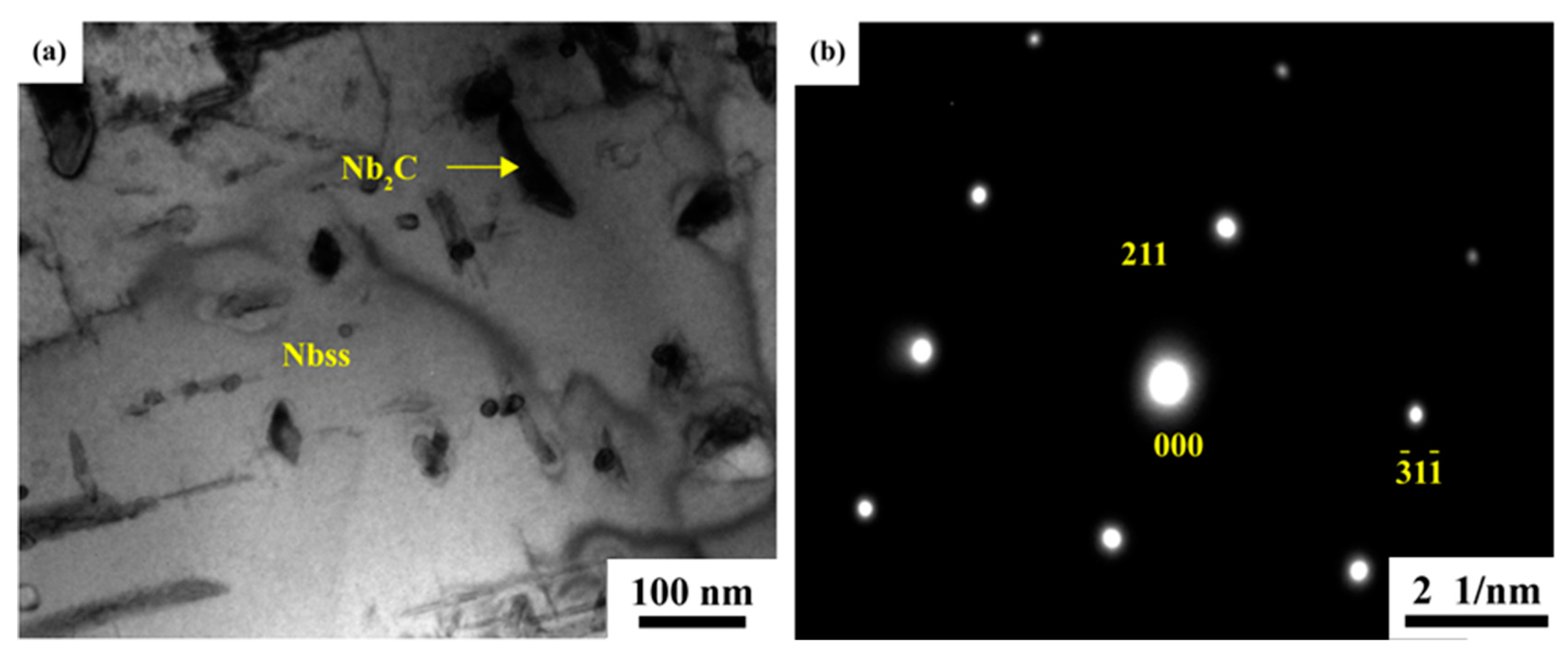
Figure 9 shows TEM images of the micron Nb2C particles in the Nb-40Si-10C alloy and diffraction patterns of Nbss/Nb2C. Nbss and Nb2C were observed in the Nb/Nb5Si3 composites, and the zone axes along [001] and [010] are presented, respectively. Furthermore, the phase relationship is [001]Nbss//[010]Nb2C, (200) Nbss//(101) Nb2C. The appearance of nano-sized Nb2C is mainly due to a change in the solid solubility of C in Nbss. According to the Nb-C binary phase diagram [30], it is clear that when the temperature is above 1500 °C, the solid solubility of C in Nbss decreases considerably with decreasing temperature. Therefore, when the prepared Nb/Nb5Si3 composites are subjected to cooling at a sintering temperature of 1750 °C, a lot of nano-sized Nb2C can be precipitated from Nbss.
Figure 10 shows TEM images and diffraction patterns typical of nanometer Nb2C in the Nb-40Si-10C alloy. Club-shaped nano-sized Nb2C particles can be observed in Figure 10a, the length and width values of which are 100–300 nm and 70–130 nm, respectively. Nb2C was also observed in the Nb-40Si-10C alloy, and the zone axes along [21 5 ¯ ] are presented in Figure 10b.
The lattice constants of each phase can be obtained by analyzing and calculating the XRD patterns of the different components of the alloy using the Jade software (MDI Jade 6.0). Table 6 shows the lattice parameters of Nbss and α-Nb5Si3 in the composites. Regarding the Nb-50Si and Nb-40Si-10C composites, the lattice parameters of Nbss and α-Nb5Si3 decreased with the addition of C. The assumption that C atoms mainly occupy the substitutional sites in Nbss and α-Nb5Si3 can be confirmed by the fact that the atomic radius of C is smaller than that of Nb and/or Si, thereby forming a replacement solid solution.
The average compressive 0.2% flow stress at 1400 °C and fracture toughness at ambient temperature are shown in Table 7. It can be seen that the mechanical properties of the Nb/Nb5Si3 composites were significantly enhanced following the addition of C. This could be attributed to the following three reasons: Firstly, the C in Nbss and Nb5Si3 played a key role in solution strengthening and improving high-temperature strength. The dissolution of carbon atoms in both the Nbss and Nb5Si3 lattices was predominantly located at substitutional sites and decreased the lattice parameters, increasing the deformation resistance. As a result, the compressive strength is influenced by the content of the strengthened phase, i.e., Nb2C. As mentioned in Table 7, with the addition of C, the volume fraction of the plastic phase decreased, while that of the strengthened phase increased. Lastly, the precipitated fine carbide played a role in enhancing the compressive strength. Allameh et al. [31] reported that, with the addition of TiC particles, some dislocations in the TiC particles were observed, and it was also reported that their interactions played a significant role in strengthening the 44Nb-35Ti-6Al-5Cr-8V-1W-0.5Mo-0.5Hf (at.%) alloy. Therefore, it can be inferred that nanoscale Nb2C in the Nb/Nb5Si3 composites will produce similar strengthening effects.
It also can be seen from Table 7 that the fracture toughness of the composites improved with the addition of C. This can be attributed to the following reasons. First, as mentioned in Figure 4, the O content in the Nbss layer can be reduced or eliminated with the addition of C. This observation also corresponded well to the fracture morphology results shown in Figure 6. It is known that a large amount of energy could be absorbed from the plastic deformation of the Nbss. When the plasticity of Nbss increased, more energy could be consumed, resulting in an increase in the fracture toughness of the composites. The ductility of Nbss can exhibit a strong resistance to crack initiation during the plastic deformation of 44Nb-35Ti-6Al-5Cr-8V-1W-0.5Mo-0.3Hf (at.%), as reported by Sikka and Loria [32].
Second, the fracture toughness can be affected by some physical properties. According to the Ashby model [33], the toughness increment ΔKC can be expressed as Equation (10):
ΔKC = (C·Vf ·E·σ0·a0)1/2
where E, Vf, σ0, and a0 are the Young’s modulus (GPa), volume fraction, yield strength at ambient temperature (MPa), and radius of the Nbss phase (m), respectively, and C is the material constant representing the degree of constraint imposed upon a ductile particle from the brittle matrix. In the current work, since the Nbss phase became deformed without interface decohesion (Figure 3), the parameter C is taken to be 1.6 [34]. The volume fraction and average radius of the Nbss can be obtained from Figure 3. The Young’s modulus and Vickers hardness were measured, and the yield strength σ0 (MPa) of Nbss phase can be estimated from the Vickers hardness of the Nbss phase using the following equation [35]:
σ0 = 2.4Hv
The mechanical and physical properties of the composites are presented in Table 8. Clearly, due to the existence of nano-sized carbide, all of the Young’s modulus, Vickers hardness, and yield strength values were increased in the C-doped composites. It has been reported that, the hardness and Young’s modulus of Nb2C is higher than that of Nbss [36]. With the addition of C, Nbss was transformed to Nb2C. Based on the rule of mixtures [32], the hardness and Young’s modulus of the Nbss layer would increase, leading to an increase in yield strength, according to Equation (11).

4. Conclusions

Laminated Nb/Nb5Si3 composites supplemented with C were prepared via spark plasma sintering. Nbss and γ-Nb5Si3 were found In the Nb-Si-C composites, and micron-sized Nb2C particles and nano-sized Nb2C were observed in the Nbss layer. The formation of Nb2C particles might be attributable to the rapid diffusion of C into the Nb foil during sintering, and the formation of nano-sized Nb2C could be attributable to C’s solid solubility change in Nbss. Additionally, with the addition of C, the compressive strength of composites at 1400 °C and the fracture toughness increased from 310 MPa and 11.9 MPa·m1/2 to 330 MPa and 14.2 MPa·m1/2, respectively; the addition of C mainly resulted in solid solution strengthening.

Author Contributions

Writing—original draft, D.Z.; Writing—review & editing, L.X., S.X., H.Y., Y.Z., C.Y., X.Z., Z.C. and W.L. All authors have read and agreed to the published version of the manuscript.

Funding

This study was supported financially by the National Natural Science Foundation of China (under Grant No. 52104285), the National Defense Supporting Project (under Grant No. 2022-027), the Natural Science Foundation of Hunan Province (under Grant No. 2020JJ5713), and the Natural Science Foundation of Hunan, China (under Grant No. 2023JJ30684).

Institutional Review Board Statement

Not applicable.

Informed Consent Statement

Not applicable.

Data Availability Statement

Not applicable.

Conflicts of Interest

The authors declare no conflict of interest.

References

  1. Hong, D.; Zeng, W.; Zhong, M.; Xu, X.; Liu, F.S.; Tang, B.; Liu, Q.J. Structural, electronic properties and boron stability of (001) surface of Nb5Si3 intermetallic by first-principles calculations. Vacuum 2020, 179, 109558. [Google Scholar] [CrossRef]
  2. Yan, J.J.; Guo, X.P. Effect of heat-treatment on microstructure and mechanical behavior of directionally solidified Nb-Ti-Si based alloy. Rare Met. Mater. Eng. 2017, 46, 1–6. [Google Scholar]
  3. Liu, W.; Huang, S.; Ye, C.T.; Kang, Y.W.; Sha, J.B.; Chen, B.Q.; Wu, Y.; Xiong, H.P. Progress in Nb-Si ultra-high temperature structural materials: A review. J. Mater. Sci. Technol. 2023, 149, 127–153. [Google Scholar] [CrossRef]
  4. Xiong, B.; Peng, F.; Wang, C.W.; Liu, K.; Wang, Z.J. Strengthening mechanisms in short carbon fiber reinforced Nb/Nb5Si3 composites with interfacial reaction. Mater. Sci. Eng. A 2021, 825, 141884. [Google Scholar] [CrossRef]
  5. Liao, J.; Fei, T.; Li, Y.; Yu, Y.X.; Sha, J.B. A comparison study on microstructures and fracture behaviours of a single NbSS solid solution alloy and a two-phase NbSS/Nb5Si3 alloy prepared by spark plasma sintering and arc melting. Mater. Charact. 2021, 178, 111259. [Google Scholar] [CrossRef]
  6. Ren, X.; Liu, W.; Ren, H.; Jing, Y.J.; Mao, W.; Xiong, H.P. Microstructures and joining characteristics of NbSS/Nb5Si3 composite joints by newly-developed Ti66-Ni22-Nb12 filler alloy. J. Mater. Sci. Technol. 2020, 58, 95–99. [Google Scholar] [CrossRef]
  7. Sun, G.; Jia, L.; Ye, C.; Jin, Z.H.; Wang, Y.; Li, H.; Zhang, H. Balancing the fracture toughness and tensile strength by multiple additions of Zr and Y in Nb–Si based alloys. Intermetallics 2021, 133, 107172. [Google Scholar] [CrossRef]
  8. Goncharov, I.; Hisamova, L.; Mustafaeva, L.; Razumov, N.; Makhmutov, T.; Kim, A.; Wang, Q.S.; Shamshurin, A.; Popovich, A. Microstructure and phase composition of the Nb-Si based in-situ composite from plasma spheroidized powder. Mater. Today Proc. 2020, 30, 545–548. [Google Scholar] [CrossRef]
  9. Wang, Y.; Jia, L.N.; Ye, C.T.; Sun, G.X.; Zhang, H. Behaviors and interactions of strengthening and constraint for ductile Nbss matrix in Nb–Si based alloys. Prog. Nat. Sci. Mater. Int. 2022, 32, 215–225. [Google Scholar] [CrossRef]
  10. Jin, Z.H.; Jia, L.N.; Ye, C.T.; Wang, W.B.; Zhang, H. Orientation dependence of microcosmic plasticity and toughness in Nb–Si alloys. J. Alloys Compd. 2023, 934, 167549. [Google Scholar] [CrossRef]
  11. Zhao, T.Y.; Wang, Q.; Chen, R.R.; Zhou, Z.C.; Su, Y.Q.; Fu, H.Z. Microstructure and mechanical properties of Nb–Si alloy with addition of Mn. J. Mater. Res. Technol. 2022, 20, 708–719. [Google Scholar] [CrossRef]
  12. Li, M.X.; Wang, H.P.; Lin, M.J.; Zheng, C.H.; Wei, B. Rapid Eutectic Growth Kinetics of Undercooled Nb–Si Alloys at Electrostatic Levitation State. Acta Mater. 2022, 237, 118157. [Google Scholar] [CrossRef]
  13. Wang, F.; Zheng, X.; Bai, R.; Cai, X.M.; Zhang, X.M.; Wang, D.H.; Li, Z.K. Microstructure and Mechanical Properties of Low-Density NbTiAlVZr Alloy. Rare Met. Mater. Eng. 2011, 40, 1972–1975. [Google Scholar]
  14. Fan, Z.J.; Niu, B.; Wang, Q.; Sha, J.J.; Dong, C. Effects of Si variation and Zr addition on the microstructure, oxidation resistance and mechanical property at 1523 K of Nb-Si-Ti/Zr/Hf-Cr/Al high-entropy superalloys. J. Alloys Compd. 2023, 945, 169304. [Google Scholar] [CrossRef]
  15. Chen, D.; Wang, Q.; Chen, R.; Zhou, Z.C.; Su, Y.Q.; Guo, J.J.; Fu, H.Z. Microstructure evolution and mechanical properties of ZrC-added Nb–16Si–20Ti alloys. Mater. Sci. Eng. A 2022, 829, 142159. [Google Scholar] [CrossRef]
  16. Li, L.F.; Guo, X.P. Microstructure and oxidation resistance of Ti modified Si–Mo coating on Nb–Si based ultrahigh temperature alloy. Corros. Sci. 2023, 220, 111293. [Google Scholar] [CrossRef]
  17. Ma, R.; Guo, X.P. Cooperative effects of Mo, V and Zr additions on the microstructure and properties of multi-elemental Nb–Si based alloys. J. Mater. Sci. Technol. 2023, 132, 27–41. [Google Scholar] [CrossRef]
  18. Wang, Q.; Zhou, C.; Wang, S.; Chen, R.R. Effect of Zr and Hf additions on microstructure and mechanical properties of Nb–Si based ultrahigh temperature alloys. J. Mater. Res. Technol. 2020, 9, 15585–15592. [Google Scholar] [CrossRef]
  19. Sun, G.; Jia, L.; Hong, Z.; Liu, G.X.; Zhang, H. Improvement of oxidation resistance of Nb–Ti–Si based alloys with additions of Al, Cr and B at different temperatures. Prog. Nat. Sci. Mater. Int. 2021, 31, 442–453. [Google Scholar] [CrossRef]
  20. Ye, C.; Jia, L.; Jin, Z.; Wang, Y.; Zhang, H. Directional solidification of hypereutectic Nb–Si–Ti alloy: Influence of drawing velocity change on microstructures. J. Alloys Compd. 2020, 844, 156123. [Google Scholar] [CrossRef]
  21. Kajuch, J.; Short, J.; Lewandowski, J.J. Deformation and fracture behavior of Nb in Nb5Si3/Nb laminates and its effect on laminate toughness. Acta Metall. Mater. 1995, 43, 1955–1967. [Google Scholar] [CrossRef]
  22. Yu, C.X.; Zhao, X.J.; Xiao, L.R.; Cai, Z.Y.; Zhang, B.; Guo, L. Microstructure and mechanical properties of in-situ laminated Nb/Nb5Si3 composites. Mater. Lett. 2017, 209, 606–608. [Google Scholar] [CrossRef]
  23. Tsakiropoulos, P. On the Alloying and Properties of Tetragonal Nb5Si3 in Nb-Silicide Based Alloys. Materials 2018, 11, 69. [Google Scholar] [CrossRef] [PubMed] [Green Version]
  24. Sun, Z.P.; Guo, X.P.; Tian, X.D.; Zhou, L. Microhardness and Macrohardness of as-Cast Nb-Ti-Si-B Alloys. Rare Met. Mater. Eng. 2015, 44, 2148–2151. [Google Scholar]
  25. Xiong, B.W.; Peng, F.; Chen, W.H.; Li, C.; Zhu, Q.Z.; Niu, Z.H.; Zheng, F.Z.; Cheng, D.Q. Outstanding strength and toughness in graphene reinforced Nb/Nb5Si3 composites with interfacial nano-phases. J. Mater. Res. Technol. 2023, 25, 2238–7854. [Google Scholar] [CrossRef]
  26. Wei, W.; Sun, J.; Zhang, S.; Liu, B.Q.; Yan, K.; Qi, J.Q.; Zhang, H. Phase precipitation behavior and mechanical properties of multi-phase Nb–Ti–C and Nb–Ti–Al–C alloys. Mater. Sci. Eng. A 2021, 815, 141218. [Google Scholar] [CrossRef]
  27. Wei, W.Q.; Lu, S.T. Effect of heat treatment on microstructure and mechanical behavior of Nb-35Ti-4C alloy. Rare Met. Mater. Eng. 2017, 46, 777–782. [Google Scholar]
  28. Wang, Q.; Zhao, T.; Chen, R.; Zhou, Z.C.; Su, Y.Q.; Fu, H.Z. Effect of C addition on microstructure and mechanical properties of Nb–Si–Ti based alloys. Mater. Sci. Eng. A 2021, 804, 140789. [Google Scholar] [CrossRef]
  29. Ding, R.G.; Jones, I.P.; Jiao, H.S. Effect of Mo and Hf on the mechanical properties and microstructure of Nb–Ti–C alloys. Mater. Sci. Eng. A 2007, 458, 126–135. [Google Scholar] [CrossRef]
  30. Woydt, M.; Huang, S.; Vleugels, J.; Mohrbacher, H.; Cannizza, E. Potentials of niobium carbide (NbC) as cutting tools and for wear protection. Int. J. Refract. Met. Hard Mater. 2018, 72, 380–387. [Google Scholar] [CrossRef]
  31. Allameh, S.M.; Hayes, R.W.; Loria, E.A.; Soboyejo, W.O. Creep behavior in an extruded β solid solution Nb–Ti base alloy. Mater. Sci. Eng. A 2002, 329, 856–862. [Google Scholar] [CrossRef]
  32. Kommineni, G.; Golla, B.R.; Alam, M.Z.; Sarkar, R.; Prasad, S. Structure-property correlation and deformation mechanisms in ductile phase (Nbss) toughened cast Nb–Si alloys. J. Alloys Compd. 2021, 873, 159832. [Google Scholar] [CrossRef]
  33. Ashby, M.F.; Blunt, F.J.; Bannister, M. Flow characteristics of highly constrained metal wires. Acta Metall. 1989, 37, 1847–1857. [Google Scholar] [CrossRef]
  34. Fang, X.; Guo, X.; Qiao, Y. Effect of Ti addition on microstructure and crystalline orientations of directionally solidified Nb–Si based alloys. Intermetallics 2020, 122, 106798. [Google Scholar] [CrossRef]
  35. Tabor, D. The Hardness of Metals; Clarendon Press: Oxford, UK, 1951. [Google Scholar]
  36. Vishwanadh, B.; Murthy, T.S.R.C.; Arya, A.; Tewari, R.; Dey, G.K. Synthesis and phase transformation mechanism of Nb2C carbide phases. J. Alloys Compd. 2016, 671, 424–434. [Google Scholar] [CrossRef]
Figure 1. Diagram of the preparation process for the niobium-based composites.
Materials 16 05637 g001
Figure 2. XRD patterns of alloys after sintering.
Materials 16 05637 g002
Figure 3. Thermodynamic data of the materials in reaction (1). (a) Molar heat capacity at constant pressure; (b) standard Gibbs free energy of the materials.
Materials 16 05637 g003
Figure 5. Thermodynamic data of the materials in reaction (4). (a) Molar heat capacity at constant pressure; (b) standard Gibbs free energy of the material.
Materials 16 05637 g005
Figure 6. SEM images taken from the fracture surface of the alloys after the three-point bending tests: (a,b) Nb-50Si alloy; (c,d) Nb-40Si-10C alloy.
Materials 16 05637 g006
Figure 7. Thermodynamic data of the materials in reactions (6) and (7): (a) Molar heat capacity at constant pressure; (b) standard Gibbs free energy of materials.
Materials 16 05637 g007
Figure 8. TEM images of Nb foil: (a) bright field image; (b) SADP of the region circled in Figure 8a.
Materials 16 05637 g008
Figure 9. TEM images of Nb2C in Nb-40Si-10C alloy: (a) the Nb2C particle in Nbss; (b) composite [010] SADP from Nb2C and [001] SADP from Nbss.
Materials 16 05637 g009
Figure 10. TEM images of nano-sized Nb2C in the Nb-40Si-10C alloy: (a) the nano-sized Nb2C precipitates in Nbss; (b) [21 5 ¯ ] SADP from carbide in the precipitated Nb2C.
Materials 16 05637 g010
Table 1. PDF card number of each XRD phase.
PhasePDF Card Number
α-Nb5Si300-009-0272
Nb2C00-015-0127
Nbss00-001-1183
γ-Nb5C303-065-2781
Table 2. Thermodynamic data of material in reaction (1).
Materials   H 298 Θ / J   S 298 Θ / J · K 1
Nb036.401
SiC−73,22016.610
Nb5Si3−451,872251.040
Nb2C−194,97464.015
Table 3. WDS composition analysis of the micro-areas in Figure 3.
PositionComposition (at%) Possible Phase
NbSiCO
197.80.90.01.3Nbss
262.837.20.00.0Nb5Si3
362.432.15.50.0C-poor Nb5Si3
462.724.612.70.0C-rich Nb5Si3
598.80.90.00.3Nbss
671.10.028.90.0Nb2C
769.90.030.10.0Nb2C
Table 4. Thermodynamic data of the materials in reaction (4).
Materials   H 298 Θ / J   S 298 Θ / J · K 1
NbO−408,77750.208
C05.732
Nb036.401
CO−110,541197.527
Table 5. Thermodynamic data of the materials in reactions (6) and (7).
Materials   H 298 Θ / J   S 298 Θ / J · K 1
Nb2C−194,97464.015
Si018.828
Nb5Si3−451,872251.040
NbSi2−138,07269.873
C05.732
Table 6. Lattice parameters of Nbss and α-Nb5Si3 in the composites.
Compositesa (Nbss)a (α-Nb5Si3)c (α-Nb5Si3)
Nb-50Si3.315196.5697111.89522
Nb-40Si-10C3.310266.5341011.86043
Table 7. Volume fractions of each phase and mechanical properties of alloys.
CompositesActual Compositions (at.%)Volume Fraction of Nbss/%Volume Fraction of Nb5Si3/%Volume Fraction of Nb2C/%Compressive Strength at 1400 °C/MPaFracture Toughness/MPa·m1/2
Nb-50SiNb-22.1Si-0.5O41.358.7031011.9
Nb-40Si-10CNb-19.2Si-4.9C-0.1O39.756.73.633014.2
Table 8. Mechanical and physical properties of alloys.
Nb-50SiNb-40Si-10C
Volume fraction of Nbss, Vf41.3 ± 0.139.7 ± 0.1
Radius of Nbss, a0 (μm)6.3 ± 0.16.1 ± 0.1
Young’s modulus, E (GPa)105.0 ± 2.1116.0 ± 2.2
Vickers hardness, Hv (MPa)279.0 ± 3.1307.0 ± 3.1
Yield strength of Nbss, σ0 (MPa)670.0 ± 4.1737.0 ± 4.5
Calculated, ΔK (MPa·m1/2)16.8 ± 0.917.9 ± 0.8
Fracture toughness, KQ (MPa·m1/2)11.9 ± 2.914.2 ± 3.2
Disclaimer/Publisher’s Note: The statements, opinions and data contained in all publications are solely those of the individual author(s) and contributor(s) and not of MDPI and/or the editor(s). MDPI and/or the editor(s) disclaim responsibility for any injury to people or property resulting from any ideas, methods, instructions or products referred to in the content.

