
The Influence of Geometry, Surface Texture, and Cooling Method on the Efficiency of Heat Dissipation through the Heat Sink—A Review

 , ,
, ,
Abstract
:1. Introduction
1.1. Heat Sinks in Engineering
1.2. Surface Asperities and Heat Sink Performance
- The density of the bubble nucleation site increases with increasing surface roughness from Ra = 0.6 µm to 1.0 µm for a larger microgap heat sink;
- Ra = 1.0 µm and 1.6 µm implies a similar boiling behavior of microgaps;
- The increment of the surface roughness implies the increment of the local heat transfer coefficients;
- During the experiment, there was no observed significant adverse effect of surface roughness on the pressure drop curve;
- Ra = 1.0 µm and above provides a more uniform wall temperature over the heat sink compared to Ra = 0.6 µm, due to the uniform distribution of the boiling process over the heating surface;
- Ra = 1.0 µm and 1.6 µm do appear to harm the inlet pressure instability compared to Ra = 0.6 µm at a larger microgap heat sink, and Ra = 1.0 µm and 1.6 µm surfaces have between 20% and 40% higher inlet pressure instability than Ra = 0.6 µm surface;
- Wall temperature fluctuations are independent of surface roughness for the microgap at various imposed heat flux and mass flux.
2. Methodology
- Conduction—at the interface between the source and the heat sink and in the volume of the heat sink itself;
- Radiation—on the surface of the heat sink;
- Convection—in the volume of the environment surrounding the heat sink.
- The heat source—a processor system of known power and dimensions;
- The heat removal element—a heat sink;
- Workspace or flow channel.
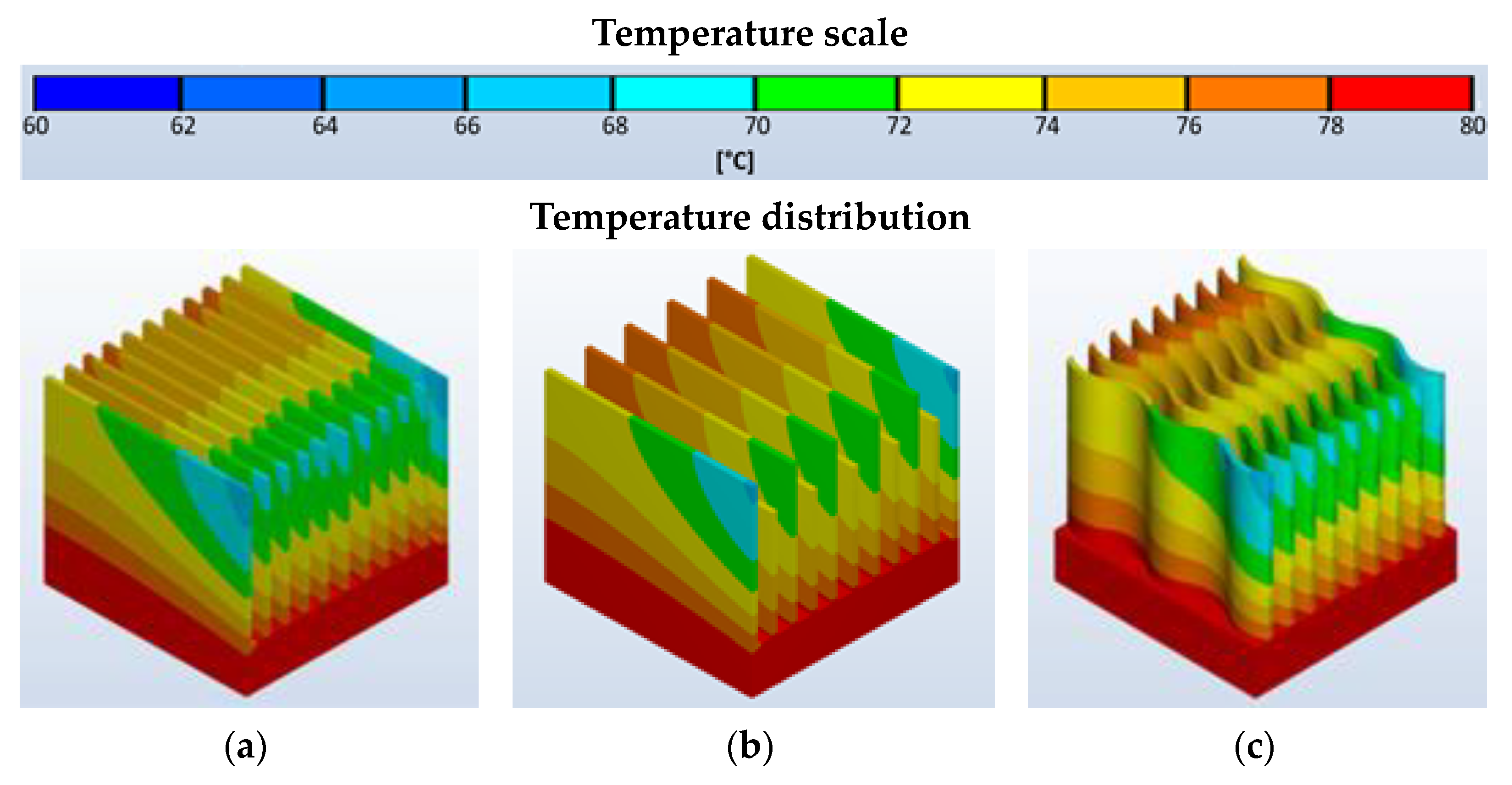
- Temperature distribution on the surface of the heat sinks;
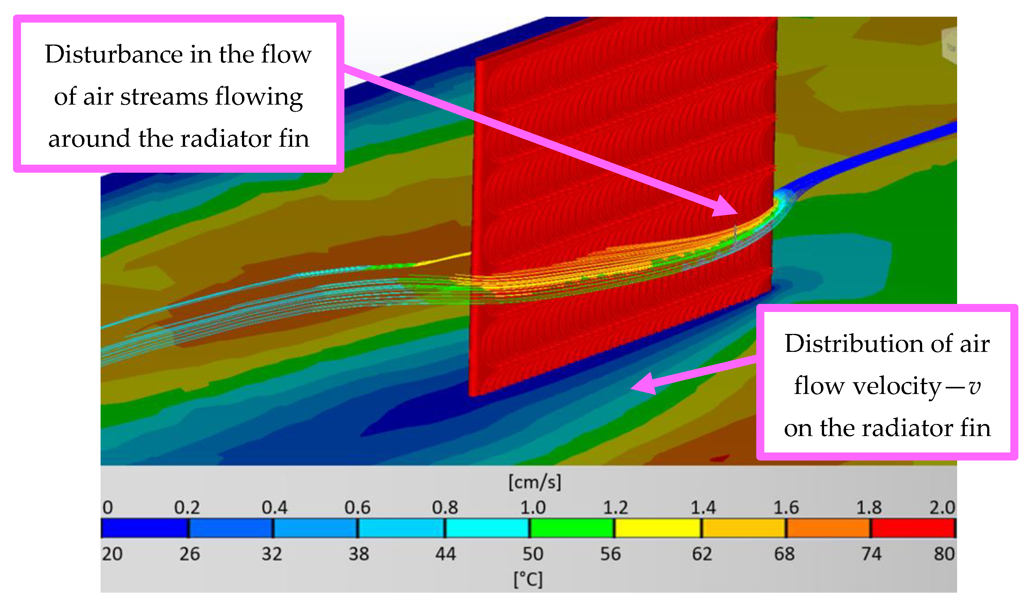
- Distribution of velocity vector fields and airflow directionality in the heatsink surroundings;
- Effective heat dissipation efficiency.
3. Results
4. Conclusions
Author Contributions
Funding
Institutional Review Board Statement
Informed Consent Statement
Data Availability Statement
Conflicts of Interest
References
- Savchuk, O.A.; Carvajal, J.J.; Brites, C.D.S.; Carlos, L.D.; Aguilo, M.; Diaz, F. Upconversion Thermometry: A New Tool to Measure the Thermal Resistance of Nanoparticles. Nanoscale 2018, 10, 6602–6610. [Google Scholar] [CrossRef] [Green Version]
- Ruan, K.; Shi, X.; Guo, Y.; Gu, J. Interfacial Thermal Resistance in Thermally Conductive Polymer Composites: A Review. Compos. Commun. 2020, 22, 100518. [Google Scholar] [CrossRef]
- Muthukumar, K.; Sabariraj, R.V.; Dinesh Kumar, S.; Sathish, T. Investigation of Thermal Conductivity and Thermal Resistance Analysis on Different Combination of Natural Fiber Composites of Banana, Pineapple and Jute. Mater. Today Proc. 2020, 21, 976–980. [Google Scholar] [CrossRef]
- Lu, H.; Xu, M.; Gong, L.; Duan, X.; Chai, J.C. Effects of Surface Roughness in Microchannel with Passive Heat Transfer Enhancement Structures. Int. J. Heat Mass Transf. 2020, 148, 119070. [Google Scholar] [CrossRef]
- Pakrouh, R.; Hosseini, M.J.; Ranjbar, A.A.; Bahrampoury, R. A Numerical Method for PCM-Based Pin Fin Heat Sinks Optimization. Energy Convers. Manag. 2015, 103, 542–552. [Google Scholar] [CrossRef]
- Mokheimer, E.M.A. Heat Transfer from Extended Surfaces Subject to Variable Heat Transfer Coefficient. Heat Mass Transf. 2003, 39, 131–138. [Google Scholar] [CrossRef]
- Abbas, A.; Qasrawi, F.; Wang, C.C. Investigation of Performance Augmentation for Natural Convective Heatsink with the Help of Chimney. Appl. Therm. Eng. 2020, 178, 115586. [Google Scholar] [CrossRef]
- Sun, L.; Zhu, J.; Wong, H. Simulation and Evaluation of the Peak Temperature in LED Light Bulb Heatsink. Microelectron. Reliab. 2016, 61, 140–144. [Google Scholar] [CrossRef]
- Shen, G.; Yang, S.; Sun, J.; Xu, S.; Pommerenke, D.J.; Khilkevich, V.V. Maximum Radiated Emissions Evaluation for the Heatsink/IC Structure Using the Measured near Electrical Field. IEEE Trans. Electromagn. Compat. 2017, 59, 1408–1414. [Google Scholar] [CrossRef]
- Covert, L.; Lin, J.; Janning, D.; Dalrymple, T. 5.8 GHz Orientation-Specific Extruded-Fin Heatsink Antennas for 3D RF System Integration. Microw. Opt. Technol. Lett. 2008, 50, 1826–1831. [Google Scholar] [CrossRef]
- Al-Omari, A.; Lear, K. VCSELs with a self-aligned contact and copper-plated heatsink. IEEE Photonics Technol. Lett. 2005, 17, 1767–1769. [Google Scholar] [CrossRef]
- Lee, G.; Kim, C.S.; Kim, S.; Kim, Y.J.; Choi, H.; Cho, B.J. Flexible Heatsink Based on a Phase-Change Material for a Wearable Thermoelectric Generator. Energy 2019, 179, 12–18. [Google Scholar] [CrossRef]
- Veismoradi, A.; Modir, A.; Ghalambaz, M.; Chamkha, A. A Phase Change/Metal Foam Heatsink for Thermal Management of Battery Packs. Int. J. Therm. Sci. 2020, 157, 106514. [Google Scholar] [CrossRef]
- Hajjar, A.; Jamesahar, E.; Shirivand, H.; Ghalambaz, M.; Babaei Mahani, R. Transient Phase Change Heat Transfer in a Metal Foam-Phase Change Material Heatsink Subject to a Pulse Heat Flux. J. Energy Storage 2020, 31, 101701. [Google Scholar] [CrossRef]
- He, X.; Hubing, T.H. A Closed-Form Expression for Estimating the Maximum Radiated Emissions from a Heatsink on a Printed Circuit Board. IEEE Trans. Electromagn. Compat. 2012, 54, 205–211. [Google Scholar] [CrossRef]
- Hernandez-Perez, J.G.; Carrillo, J.G.; Bassam, A.; Flota-Banuelos, M.; Patino-Lopez, L.D. A New Passive PV Heatsink Design to Reduce Efficiency Losses: A Computational and Experimental Evaluation. Renew. Energy 2020, 147, 1209–1220. [Google Scholar] [CrossRef]
- Huang, H.; Wang, H.; Gu, J.; Wu, Y. High-dimensional model representation-based global sensitivity analysis and the design of a novel thermal management system for lithium-ion batteries. Energy Convers. Manag. 2019, 190, 54–72. [Google Scholar] [CrossRef]
- Luo, X.; Li, E. A surrogate-assisted thermal optimization framework for design of pin-fin heat sink for the platform inertial navigation system. Eng. Optim. 2020, 53, 145–164. [Google Scholar] [CrossRef]
- Boccardi, S.; Ciampa, F.; Meo, M. Design and Development of a Heatsink for Thermo-Electric Power Harvesting in Aerospace Applications. Smart Mater. Struct. 2019, 28, 105057. [Google Scholar] [CrossRef]
- Abbas, A.; Muneeshwaran, M.; Wang, C.C. Performance of Displaced Fin Heatsink in Natural Convection Subject to Upward and Downward Arrangement. Int. J. Therm. Sci. 2021, 162, 106797. [Google Scholar] [CrossRef]
- Brench, C.E. Heatsink Radiation as a Function of Geometry. In Proceedings of the IEEE Symposium on Electromagnetic Compatibility, Chicago, IL, USA, 22–26 August 1994; pp. 105–109. [Google Scholar] [CrossRef]
- Ong, K.S.; Tan, C.F.; Lai, K.C.; Tan, K.H. Heat Spreading and Heat Transfer Coefficient with Fin Heat Sink. Appl. Therm. Eng. 2017, 112, 1638–1647. [Google Scholar] [CrossRef]
- Duda, P.; Mazurkiewicz, G. Numerical Modeling of Heat and Mass Transfer in Cylindrical Ducts. Arch. Thermodyn. 2010, 31, 33–43. [Google Scholar] [CrossRef]
- Liu, X.; Zhang, M.; Wang, Z.; Chen, J.; Sun, H.; Sun, H. Numerical Analysis of Fluid Flow and Heat Transfer in Micro-Channel Heat Sinks with Double-Layered Complex Structure. Micromachines 2020, 11, 146. [Google Scholar] [CrossRef] [PubMed] [Green Version]
- Shahsavar, A.; Baseri, M.M.; Al-Rashed, A.A.A.A.; Afrand, M. Numerical Investigation of Forced Convection Heat Transfer and Flow Irreversibility in a Novel Heatsink with Helical Microchannels Working with Biologically Synthesized Water-Silver Nano-Fluid. Int. Commun. Heat Mass Transf. 2019, 108, 104324. [Google Scholar] [CrossRef]
- Im, D.H.; Kwon, H.C.; Kim, K.J.; Kim, K.H. Study on the Design of a New Heatsink Cooling System for Thermoelectric Dehumidifier. Int. J. Precis. Eng. Manuf. 2020, 21, 75–80. [Google Scholar] [CrossRef]
- Ho, C.J.; Liu, Y.-C.; Yang, T.-F.; Ghalambaz, M.; Yan, W.-M. Convective Heat Transfer of Nano-Encapsulated Phase Change Material Suspension in a Divergent Minichannel Heatsink. Int. J. Heat Mass Transf. 2021, 165, 120717. [Google Scholar] [CrossRef]
- Li, H.Y.; Chao, S.M. Measurement of Performance of Plate-Fin Heat Sinks with Cross Flow Cooling. Int. J. Heat Mass Transf. 2009, 52, 2949–2955. [Google Scholar] [CrossRef]
- Kumar, S.; Sarkar, M.; Singh, P.K.; Lee, P.S. Study of Thermal and Hydraulic Performance of Air Cooled Minichannel Heatsink with Novel Geometries. Int. Commun. Heat Mass Transf. 2019, 103, 31–42. [Google Scholar] [CrossRef]
- Chiu, H.C.; Jang, J.H.; Yeh, H.W.; Wu, M.S. The Heat Transfer Characteristics of Liquid Cooling Heatsink Containing Microchannels. Int. J. Heat Mass Transf. 2011, 54, 34–42. [Google Scholar] [CrossRef]
- Ning, P.; Lei, G.; Wang, F.; Ngo, K.D.T. Selection of Heatsink and Fan for High-Temperature Power Modules under Weight Constraint. In Proceedings of the 2008 Twenty-Third Annual IEEE Applied Power Electronics Conference and Exposition, Austin, TX, USA, 24–28 February 2008; IEEE: Washington, DC, USA, 2008; pp. 192–198. [Google Scholar]
- Hoang, C.H.; Fallahtafti, N.; Rangarajan, S.; Gharaibeh, A.; Hadad, Y.; Arvin, C.; Sikka, K.; Schiffres, S.N.; Sammakia, B. Impact of Fin Geometry and Surface Roughness on Performance of an Impingement Two-Phase Cooling Heat Sink. Appl. Therm. Eng. 2021, 198, 117453. [Google Scholar] [CrossRef]
- Sterr, B.; Mahravan, E.; Kim, D. Uncertainty Quantification of Heat Transfer in a Microchannel Heat Sink with Random Surface Roughness. Int. J. Heat Mass Transf. 2021, 174, 121307. [Google Scholar] [CrossRef]
- Alam, T.; Lee, P.S.; Yap, C.R. Effects of Surface Roughness on Flow Boiling in Silicon Microgap Heat Sinks. Int. J. Heat Mass Transf. 2013, 64, 28–41. [Google Scholar] [CrossRef]
- Oguntala, G.; Sobamowo, G.; Ahmed, Y.; Abd-Alhameed, R. Thermal Prediction of Convective-Radiative Porous Fin Heatsink of Functionally Graded Material Using Adomian Decomposition Method. Computation 2019, 7, 19. [Google Scholar] [CrossRef] [Green Version]
- Ma, Y.; Shahsavar, A.; Talebizadehsardari, P. Two-Phase Mixture Simulation of the Effect of Fin Arrangement on First and Second Law Performance of a Bifurcation Microchannels Heatsink Operated with Biologically Prepared Water-Ag Nanofluid. Int. Commun. Heat Mass Transf. 2020, 114, 104554. [Google Scholar] [CrossRef]
- Chamkha, A.; Veismoradi, A.; Ghalambaz, M.; Talebizadehsardari, P. Phase Change Heat Transfer in an L-Shape Heatsink Occupied with Paraffin-Copper Metal Foam. Appl. Therm. Eng. 2020, 177, 115493. [Google Scholar] [CrossRef]
- Ho, C.J.; Liu, Y.-C.; Ghalambaz, M.; Yan, W.-M. Forced Convection Heat Transfer of Nano-Encapsulated Phase Change Material (NEPCM) Suspension in a Mini-Channel Heatsink. Int. J. Heat Mass Transf. 2020, 155, 119858. [Google Scholar] [CrossRef]
- Ventola, L.; Chiavazzo, E.; Calignano, F.; Manfredi, D.; Asinari, P. Heat Transfer Enhancement by Finned Heat Sinks with Micro-Structured Roughness. J. Phys. Conf. Ser. 2014, 494, 012009. [Google Scholar] [CrossRef]
- Wu, T.; Wang, Z.; Ozpineci, B.; Chinthavali, M.; Campbell, S. Automated Heatsink Optimization for Air-Cooled Power Semiconductor Modules. IEEE Trans. Power Electron. 2019, 34, 5027–5031. [Google Scholar] [CrossRef]
- You, Y.; Zhang, B.; Tao, S.; Liang, Z.; Tang, B.; Zhou, R.; Yuan, D. Effect of Surface Microstructure on the Heat Dissipation Performance of Heat Sinks Used in Electronic Devices. Micromachines 2021, 12, 265. [Google Scholar] [CrossRef]
- Bornoff, R.; Parry, J. An Additive Design Heatsink Geometry Topology Identification and Optimisation Algorithm. Annu. IEEE Semicond. Therm. Meas. Manag. Symp. 2015, 2015, 303–308. [Google Scholar] [CrossRef]
- Guo, L.; Xu, H.; Gong, L. Influence of Wall Roughness Models on Fluid Flow and Heat Transfer in Microchannels. Appl. Therm. Eng. 2015, 84, 399–408. [Google Scholar] [CrossRef]
- Ghani, I.A.; Che Sidik, N.A.; Kamaruzzaman, N.; Jazair Yahya, W.; Mahian, O. The Effect of Manifold Zone Parameters on Hydrothermal Performance of Micro-Channel HeatSink: A Review. Int. J. Heat Mass Transf. 2017, 109, 1143–1161. [Google Scholar] [CrossRef]
- Moradikazerouni, A.; Afrand, M.; Alsarraf, J.; Wongwises, S.; Asadi, A.; Nguyen, T.K. Investigation of a Computer CPU Heat Sink under Laminar Forced Convection Using a Structural Stability Method. Int. J. Heat Mass Transf. 2019, 134, 1218–1226. [Google Scholar] [CrossRef]
- Rajabifar, B. Enhancement of the Performance of a Double Layered Microchannel Heatsink Using PCM Slurry and Nanofluid Coolants. Int. J. Heat Mass Transf. 2015, 88, 627–635. [Google Scholar] [CrossRef]
- Rubio-Jimenez, C.A.; Hernandez-Guerrero, A.; Cervantes, J.G.; Lorenzini-Gutierrez, D.; Gonzalez-Valle, C.U. CFD Study of Constructal Microchannel Networks for Liquid-Cooling of Electronic Devices. Appl. Therm. Eng. 2016, 95, 374–381. [Google Scholar] [CrossRef]
- Choi, J.; Jeong, M.; Yoo, J.; Seo, M. A New CPU Cooler Design Based on an Active Cooling Heatsink Combined with Heat Pipes. Appl. Therm. Eng. 2012, 44, 50–56. [Google Scholar] [CrossRef]
- Deng, D.; Pi, G.; Zhang, W.; Wang, P.; Fu, T. Numerical Study of Double-Layered Microchannel Heat Sinks with Different Cross-Sectional Shapes. Entropy 2019, 21, 16. [Google Scholar] [CrossRef]
- Annuar, K.A.M.; Ismail, F.S. Optimal Pin Fin Arrangement of Heat Sink Design and Thermal Analysis for Central Processing Unit. In Proceedings of the 2014 5th International Conference on Intelligent and Advanced Systems: Technological Convergence for Sustainable Future, ICIAS 2014—Proceedings 2014, Kuala Lumpur, Malaysia, 3–5 June 2014. [Google Scholar] [CrossRef]
- Dammak, K.; ELHami, A. Thermal reliability-based design optimization using Kriging model of PCM based pin fin heat sink. Int. J. Heat Mass Transf. 2021, 166, 120745. [Google Scholar] [CrossRef]
- Ekpu, M.; Bhatii, R.; Ekere, N.; Mallik, S. Advanced Thermal Management Materials for Heat Sinks Used in Microelectronics. In Proceedings of the EMPC-2011—18th European Microelectronics and Packaging Conference, Brighton, UK, 12–15 September 2011. [Google Scholar]
- Ghalambaz, M.; Zhang, J. Conjugate Solid-Liquid Phase Change Heat Transfer in Heatsink Filled with Phase Change Material-Metal Foam. Int. J. Heat Mass Transf. 2020, 146, 118832. [Google Scholar] [CrossRef]
- Yamada, Y.; Yanase, M.; Miura, D.; Chikuba, K. Novel Heatsink for Power Semiconductor Module Using High Thermal Conductivity Graphite. Microelectron. Reliab. 2016, 64, 484–488. [Google Scholar] [CrossRef]
- Dai, B.; Li, M.; Ma, Y. Effect of Surface Roughness on Liquid Friction and Transition Characteristics in Micro- and Mini-Channels. Appl. Therm. Eng. 2014, 67, 283–293. [Google Scholar] [CrossRef]
- Oguntala, G.; Abd-Alhameed, R.; Sobamowo, G.; Abdullahi, H.S. Improved thermal management of computer microprocessors using cylindrical-coordinate micro-fin heat sink with artificial surface roughness. Eng. Sci. Technol. Int. J. 2018, 21, 736–744. [Google Scholar] [CrossRef]
- Koo, J.; Kleinstreuer, C. Analysis of Surface Roughness Effects on Heat Transfer in Micro-Conduits. Int. J. Heat Mass Transf. 2005, 48, 2625–2634. [Google Scholar] [CrossRef]
- Basyigit, I.B.; Genc, A.; Dogan, H.; Senel, F.A.; Helhel, S. Deep Learning for Both Broadband Prediction of the Radiated Emission from Heatsinks and Heatsink Optimization. Eng. Sci. Technol. Int. J. 2021, 24, 706–714. [Google Scholar] [CrossRef]
- Li, Y.; Wang, H.; Deng, X. Image-based reconstruction for a 3D-PFHS heat transfer problem by ReConNN. Int. J. Heat Mass Transf. 2019, 134, 656–667. [Google Scholar] [CrossRef] [Green Version]
- Samake, A.; Kocanda, P.; Kos, A. Effective Approach of Microprocessor Throughput Enhancement. Microelectron. Int. 2019, 36, 14–21. [Google Scholar] [CrossRef]
- De Mey, G.; Kos, A. The Influence of an Additional Sensor on the Microprocessor Temperature. Energies 2020, 13, 3156. [Google Scholar] [CrossRef]
- Casanova, J.J.; Taylor, J.A.; Lin, J. Design of a 3-D Fractal Heatsink Antenna. IEEE Antennas Wirel. Propag. Lett. 2010, 9, 1061–1064. [Google Scholar] [CrossRef]
- Ramesh, K.N.; Sharma, T.K.; Rao, G.A.P. Latest Advancements in Heat Transfer Enhancement in the Micro-Channel Heat Sinks: A Review; Springer: Dordrecht, The Netherlands, 2021; Volume 28, ISBN 0123456789. [Google Scholar]
- Elghool, A.; Basrawi, F.; Ibrahim, T.K.; Habib, K.; Ibrahim, H.; Idris, D.M.N.D. A Review on Heat Sink for Thermo-Electric Power Generation: Classifications and Parameters Affecting Performance. Energy Convers. Manag. 2017, 134, 260–277. [Google Scholar] [CrossRef]
- Zhang, J.; Zhu, X.; Mondejar, M.E.; Haglind, F. A Review of Heat Transfer Enhancement Techniques in Plate Heat Exchangers. Renew. Sustain. Energy Rev. 2019, 101, 305–328. [Google Scholar] [CrossRef]
- Wang, C.C. A Quick Overview of Compact Air-Cooled Heat Sinks Applicable for Electronic Cooling—Recent Progress. Inventions 2017, 2, 5. [Google Scholar] [CrossRef] [Green Version]
- Husain, A.; Kim, K. Design of Microchannel Heat Sink with Numerical Optimization Techniques. In Proceedings of the 9th Asian International Conference on Fluid Machinery, Jeju, Republic of Korea, 16–19 October 2007. [Google Scholar]
- Kinal, G.; Gęstwa, W. The influence of surface roughness on microstructure and some properties of steel elements hardened in nanofluids. Inżynieria Mater. 2015, 208, 428–432. [Google Scholar] [CrossRef]
- Maisuria, M. Effect of Surface Roughness on Heat Transfer. In Proceedings of the 3rd International Conference on Mechanical, Automotive and Materials Engineering (ICMAME’ 2013), Singapore, 29 April–3 May 2013. [Google Scholar]
- Alias, B.A.; Kuwagi, K.; Mokhtar, B.M.A.; Takami, T.; Horio, M. Numerical Experiment on Effect of Surface Roughness for Heat and Flow around Two Contacting Particles. In Proceedings of the 13th International Conference on Fluidization—New Paradigm in Fluidization Engineering, Gyeong-ju, Republic of Korea, 16–21 May 2010. [Google Scholar]
- Subramanian, A.; Gamannossi, A.; Mazzei, L.; Andreini, A. Numerical Investigation of Surface Roughness Effects on Heat Transfer in a Turbine Cascade. In AIP Conference Proceedings 2191; AIP Publishing: New York, NY, USA, 2019; p. 020143-2. [Google Scholar] [CrossRef]
- Bai, T.; Liu, J.; Zhang, W.; Zou, Z. Effect of surface roughness on the aerodynamic performance of turbine blade cascade. Propuls. Power Res. 2014, 3, 82–89. [Google Scholar] [CrossRef] [Green Version]
- Chhanwal, N.; Anishaparvin, A.; Indrani, D.; Raghavarao, K.S.M.S.; Anandharamakrishnan, C. Computational fluid dynamics (CFD) modeling of an electrical heating oven for bread-baking process. J. Food Eng. 2010, 100, 452–460. [Google Scholar] [CrossRef]
- Adamczyk, W.P.; Białecki, R.A.; Kruczek, T. Retrieving thermal conductivities of isotropic and orthotropic materials. Appl. Math. Model. 2016, 40, 3410–3421. [Google Scholar] [CrossRef]
- Li, X.; Yan, Y.; Tu, J. Evaluation of models and methods to simulate thermal radiation in indoor spaces. Build. Environ. 2018, 144, 259–267. [Google Scholar] [CrossRef]
- Urielli, I. Thermodynamic Properties Tables and Charts, Engineering Thermodynamics—A Graphical Approach; Ohio University Mechanical Engineering Department: Athens, OH, USA, 2010. [Google Scholar]
- Lide, D.R. Standard Thermodynamic Quantities: Standard Thermodynamic Quantities for Chemical Substances at 25 °C. In CRC Handbook of Chemistry and Physics, 84th ed.; CRC Press: Boca Raton, FL, USA, 2004. [Google Scholar]
- Jakubek, B.; Barczewski, R. The Influence of Kinematic Viscosity of a Lubricant on Broadband Rolling Bearing Vibrations in Amplitude Terms. Diagnostyka 2018, 20, 93–102. [Google Scholar] [CrossRef]
- Jakubek, B.; Barczewski, R.; Rukat, W.; Rozanski, L.; Wrobel, M. Stabilization of Vibro-Thermal Processes during Post-Production Testing of Rolling Bearings. Diagnostyka 2019, 20, 53–62. [Google Scholar] [CrossRef]


| Material Density —ρ [kg/m3] | Specific Heat Capacity—c [J/(kg*K)] | Conductivity Type | Thermal Conductivity —k [W/(m*K)] | Emissivity —ε |
|---|---|---|---|---|
| 2707 | 896 | Isotropic | 2.04 | 0.2 |
| Passive Cooling | Active Cooling | |
|---|---|---|
| Atmospheric pressure—p [Pa] | 101,325 | 101,325 |
| Air temperature—t [°C] | 20.00 | 20.00 |
| Source temperature—t [°C] | 80.00 | 80.00 |
| Cooling fan revolution speed—ω [rad/s] | - | 628 |
| Volumetric air flow rate—Q [l/min] | - | 90 |
| Maximum airflow velocity—v [m/s] | - | 0.02 |
| Mesh size—[mm] | 0.18 | 0.18 |
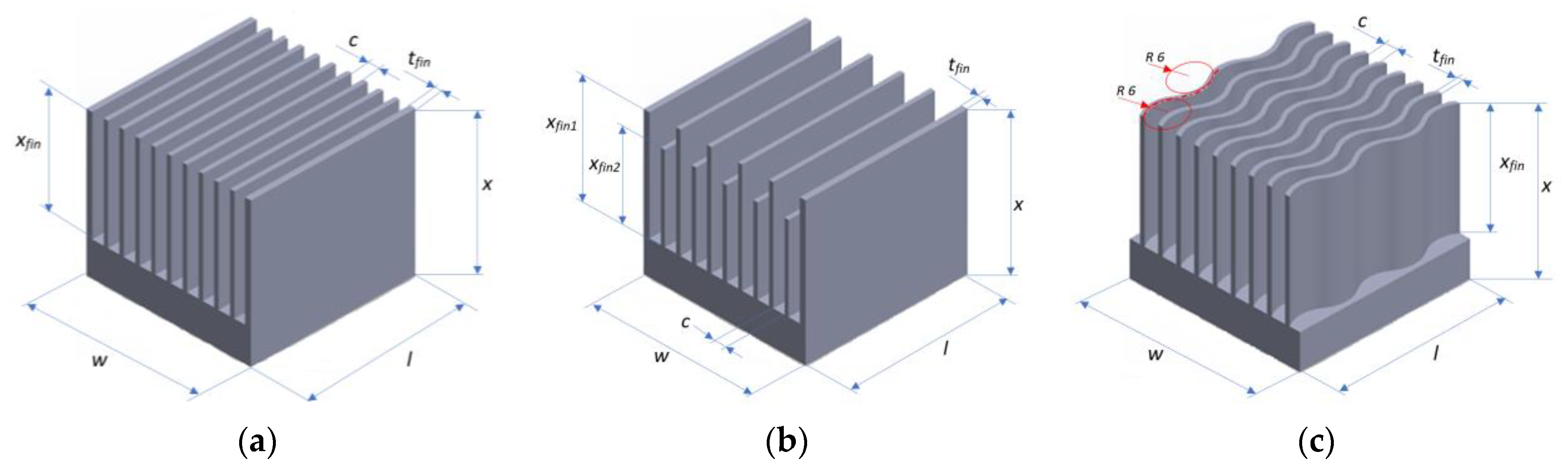
| Heat Sink with Straight Fins of Equal Height | ||||||
|---|---|---|---|---|---|---|
| x [mm] | w [mm] | l [mm] | c [mm] | tfin [mm] | xfin [mm] | |
| 34 | 37.5 | 37.5 | 2.6 | 1 | 26 | |
| Heat sink with straight ribs with two alternating heights | ||||||
| x [mm] | w [mm] | l [mm] | c [mm] | tfin [mm] | xfin 1 [mm] | xfin 2 [mm] |
| 34 | 37.5 | 37.5 | 2.6 | 1 | 26 | 20 |
| Heat sink with wave-shaped fins of equal height | ||||||
| x [mm] | w [mm] | l [mm] | c [mm] | tfin [mm] | xfin [mm] | r [mm] |
| 34 | 37.5 | 37.5 | 3 | 1 | 26 | 6.5 |
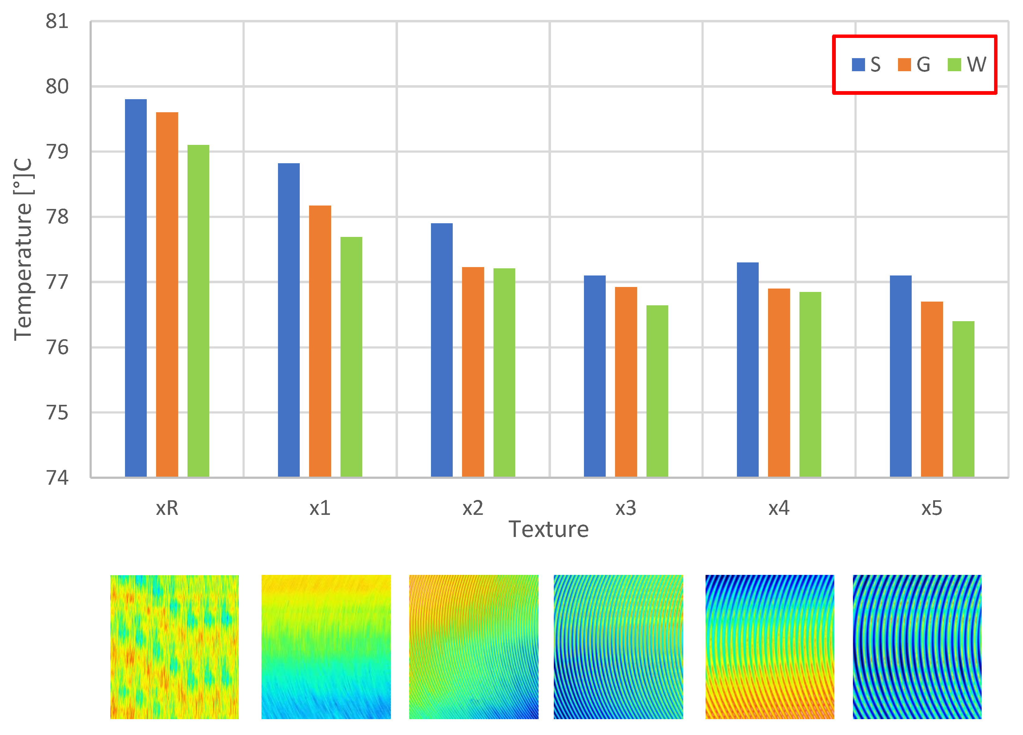
| Surface Texture | |||||||
|---|---|---|---|---|---|---|---|
| Reference—Polished xR | x1 | x2 | x3 | x4 | x5 | ||
| Geometry | Straight (S) | SR | S1 | S2 | S3 | S4 | S5 |
| Graduated (G) | GR | G1 | G2 | G3 | G4 | G5 | |
| Wave (W) | WR | W1 | W2 | W3 | W4 | W5 | |
| Sq | Sp | Sv | Sz | Sa | |
|---|---|---|---|---|---|
| [µm] | [µm] | [µm] | [µm] | [µm] | |
| xR | 0.87 | 4.03 | 4.47 | 8.50 | 0.69 |
| x1 | 3.18 | 13.78 | 10.12 | 23.90 | 2.69 |
| x2 | 6.08 | 19.00 | 16.37 | 35.36 | 4.98 |
| x3 | 9.35 | 36.62 | 19.14 | 55.76 | 7.66 |
| x4 | 13.21 | 65.00 | 22.62 | 87.62 | 10.51 |
| x5 | 23.88 | 66.40 | 57.23 | 123.63 | 19.91 |
Disclaimer/Publisher’s Note: The statements, opinions and data contained in all publications are solely those of the individual author(s) and contributor(s) and not of MDPI and/or the editor(s). MDPI and/or the editor(s) disclaim responsibility for any injury to people or property resulting from any ideas, methods, instructions or products referred to in the content. |
© 2023 by the authors. Licensee MDPI, Basel, Switzerland. This article is an open access article distributed under the terms and conditions of the Creative Commons Attribution (CC BY) license (https://creativecommons.org/licenses/by/4.0/).
Share and Cite
Grochalski, K.; Rukat, W.; Jakubek, B.; Wieczorowski, M.; Słowiński, M.; Sarbinowska, K.; Graboń, W. The Influence of Geometry, Surface Texture, and Cooling Method on the Efficiency of Heat Dissipation through the Heat Sink—A Review. Materials 2023, 16, 5348. https://doi.org/10.3390/ma16155348
Grochalski K, Rukat W, Jakubek B, Wieczorowski M, Słowiński M, Sarbinowska K, Graboń W. The Influence of Geometry, Surface Texture, and Cooling Method on the Efficiency of Heat Dissipation through the Heat Sink—A Review. Materials. 2023; 16(15):5348. https://doi.org/10.3390/ma16155348
Chicago/Turabian StyleGrochalski, Karol, Wojciech Rukat, Bartosz Jakubek, Michał Wieczorowski, Marcin Słowiński, Karolina Sarbinowska, and Wiesław Graboń. 2023. "The Influence of Geometry, Surface Texture, and Cooling Method on the Efficiency of Heat Dissipation through the Heat Sink—A Review" Materials 16, no. 15: 5348. https://doi.org/10.3390/ma16155348