
Effect of Shielding Gas Arc Welding Process on Cavitation Resistance of Welded Joints of AlMg4.5Mn Alloy

Abstract
:1. Introduction
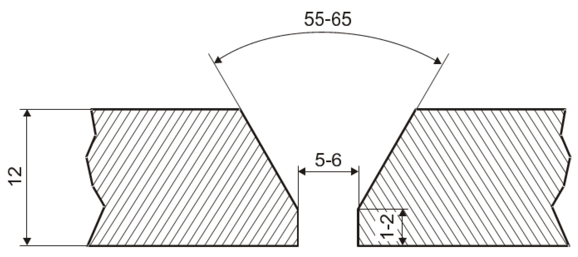
2. Materials
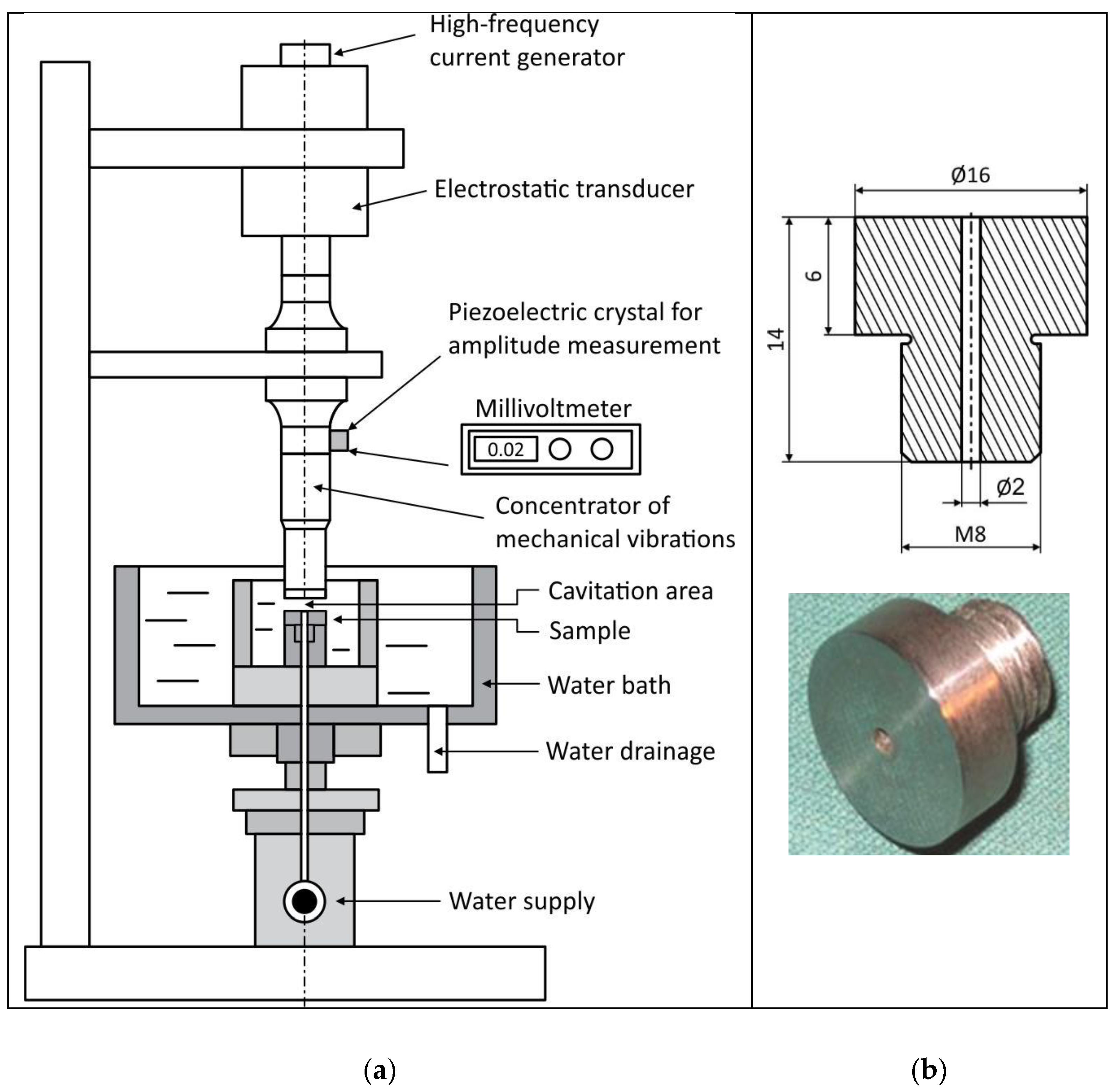
3. Testing Methods
4. Results and Discussion
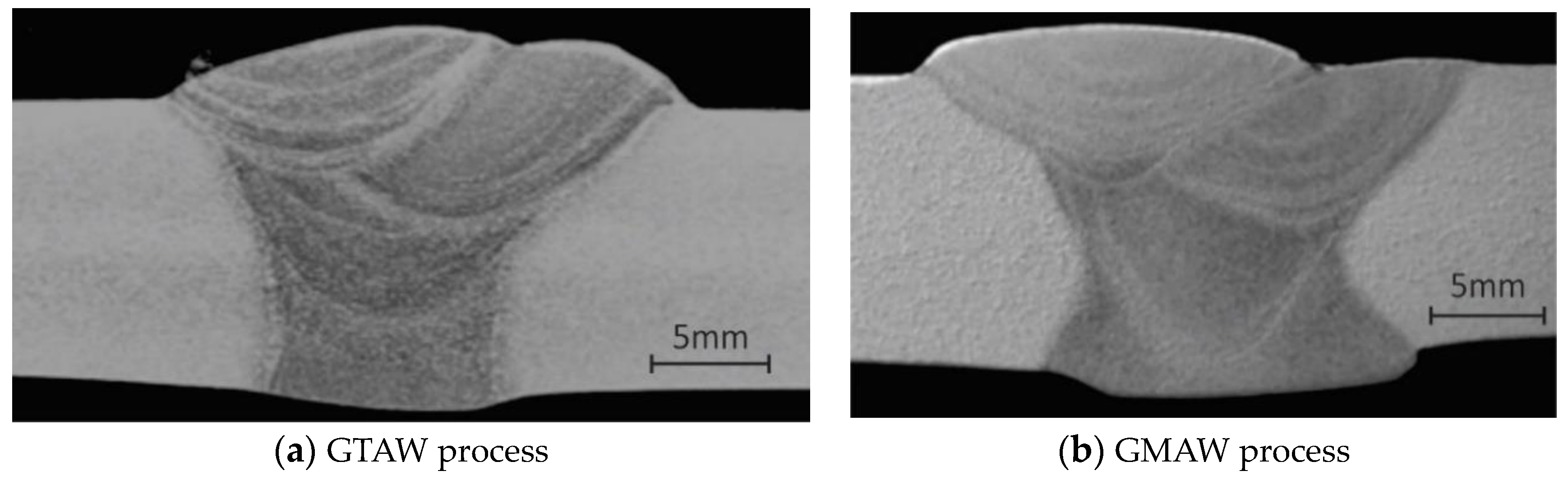
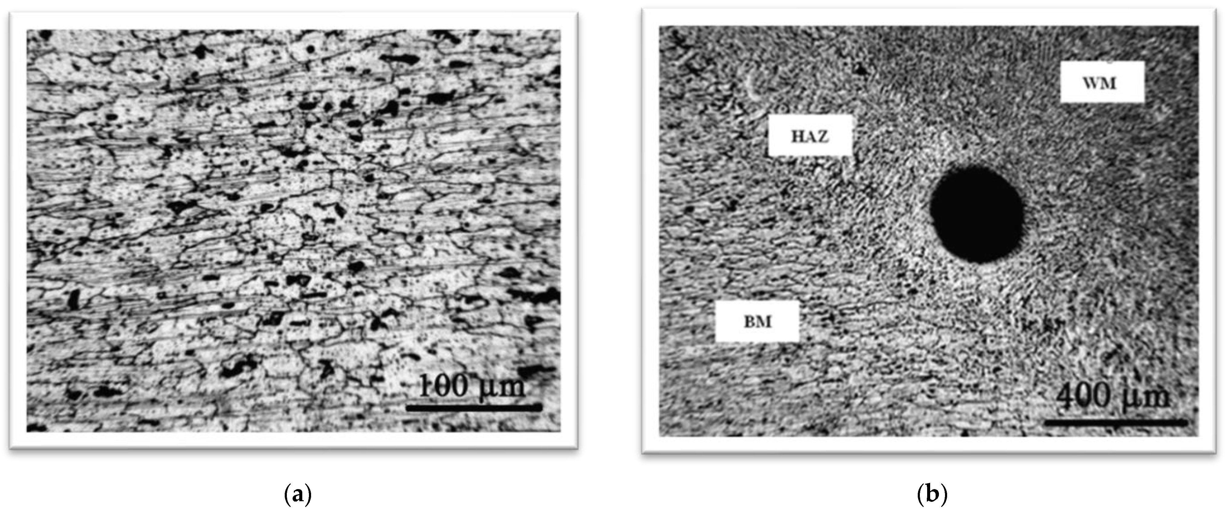
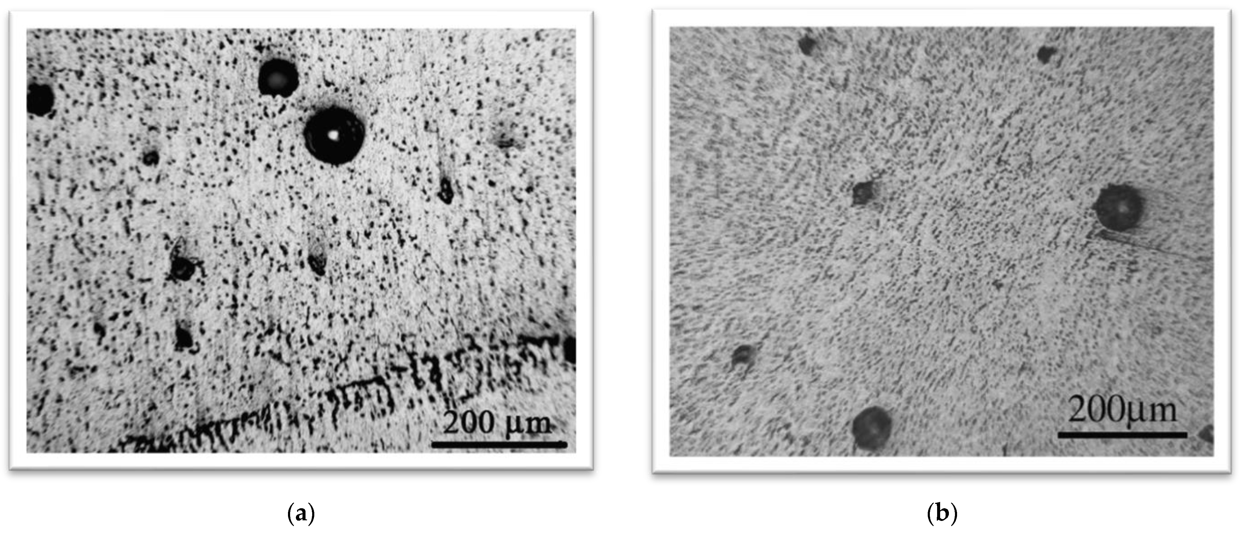
4.1. Metallographic Tests
4.2. Hardness Test
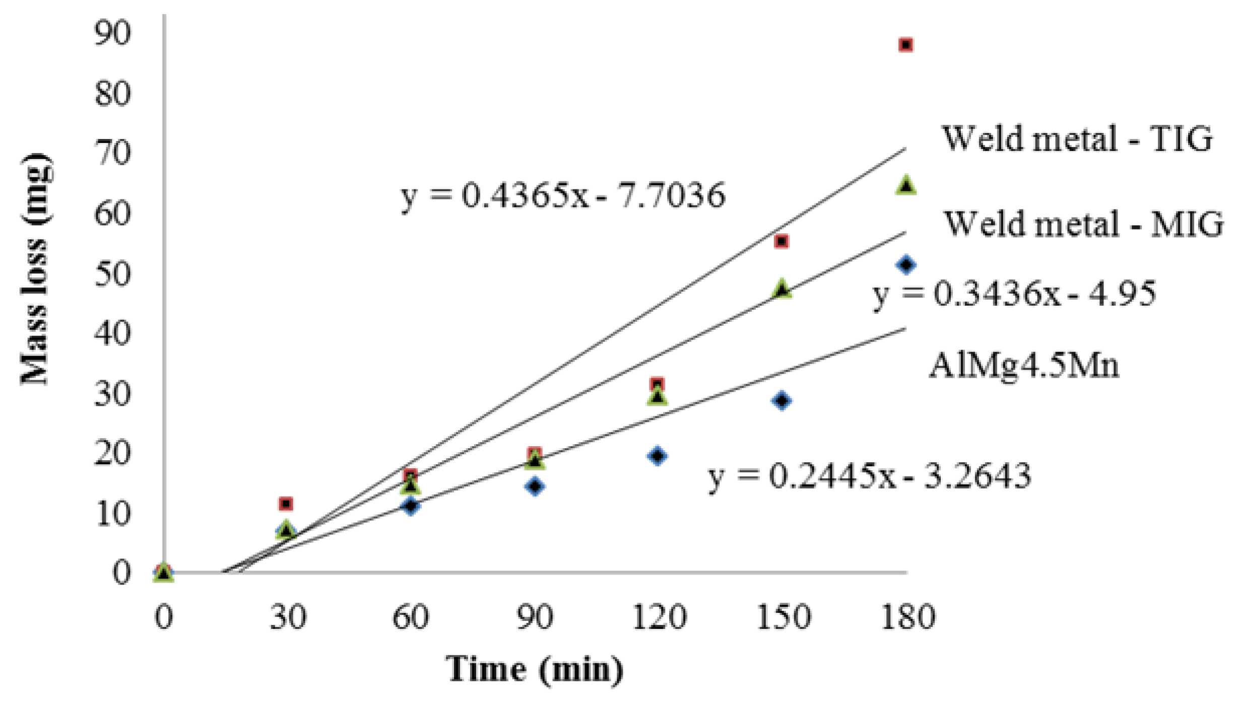
4.3. Cavitation Rates
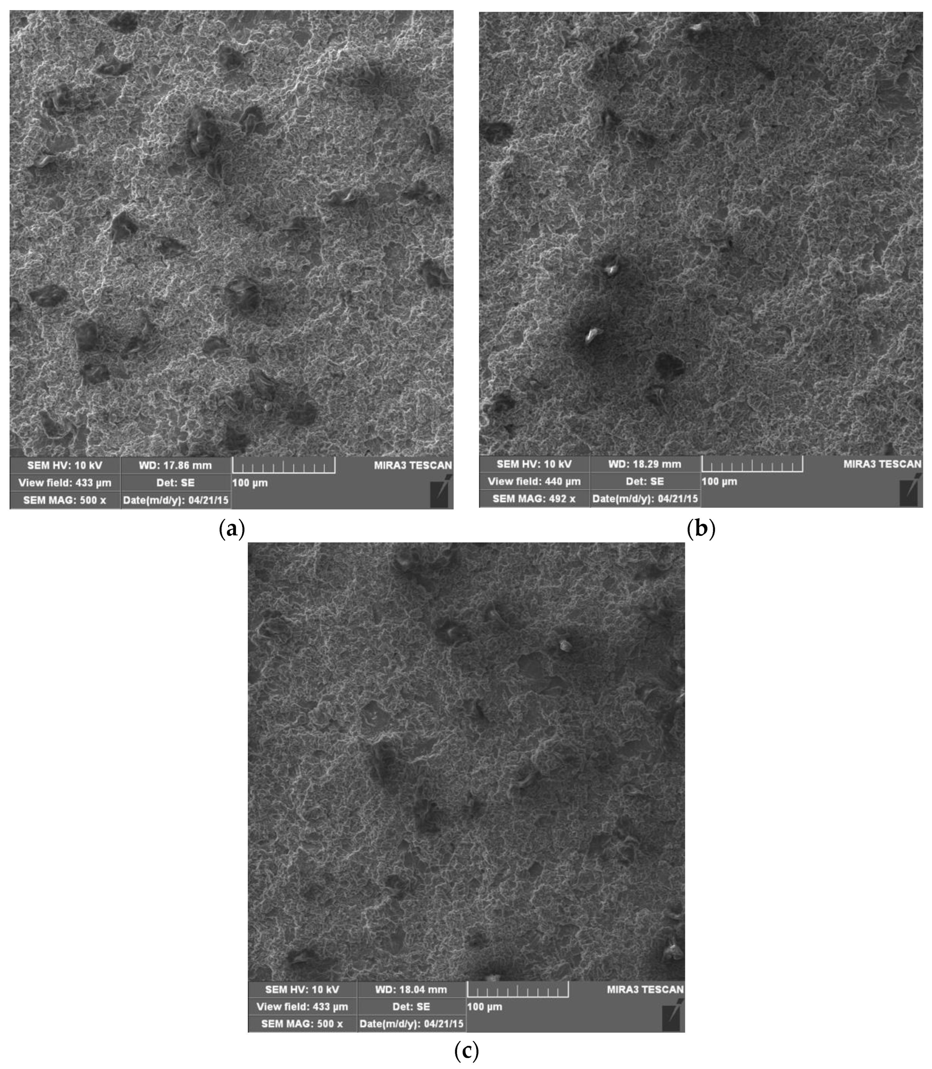
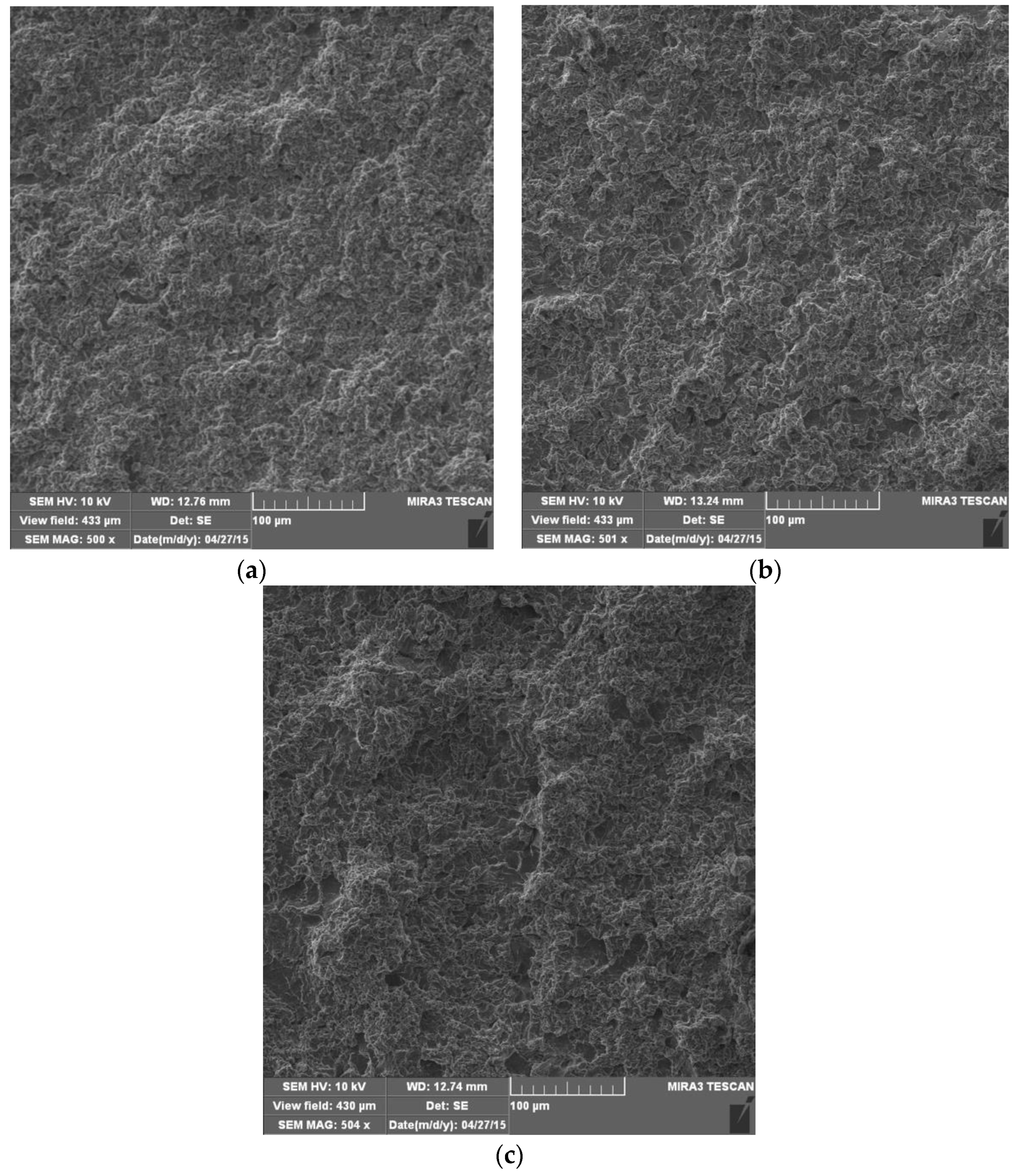
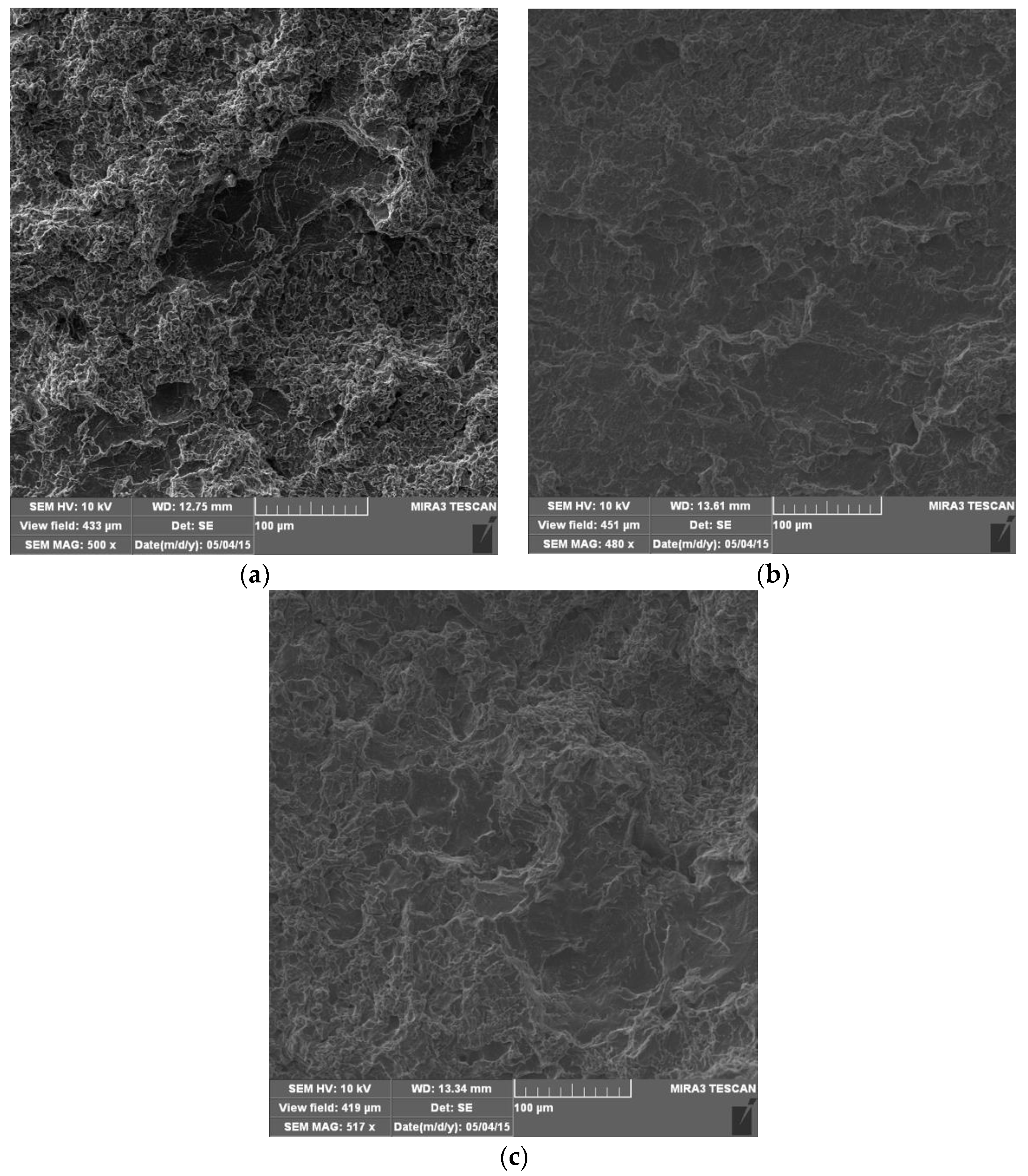
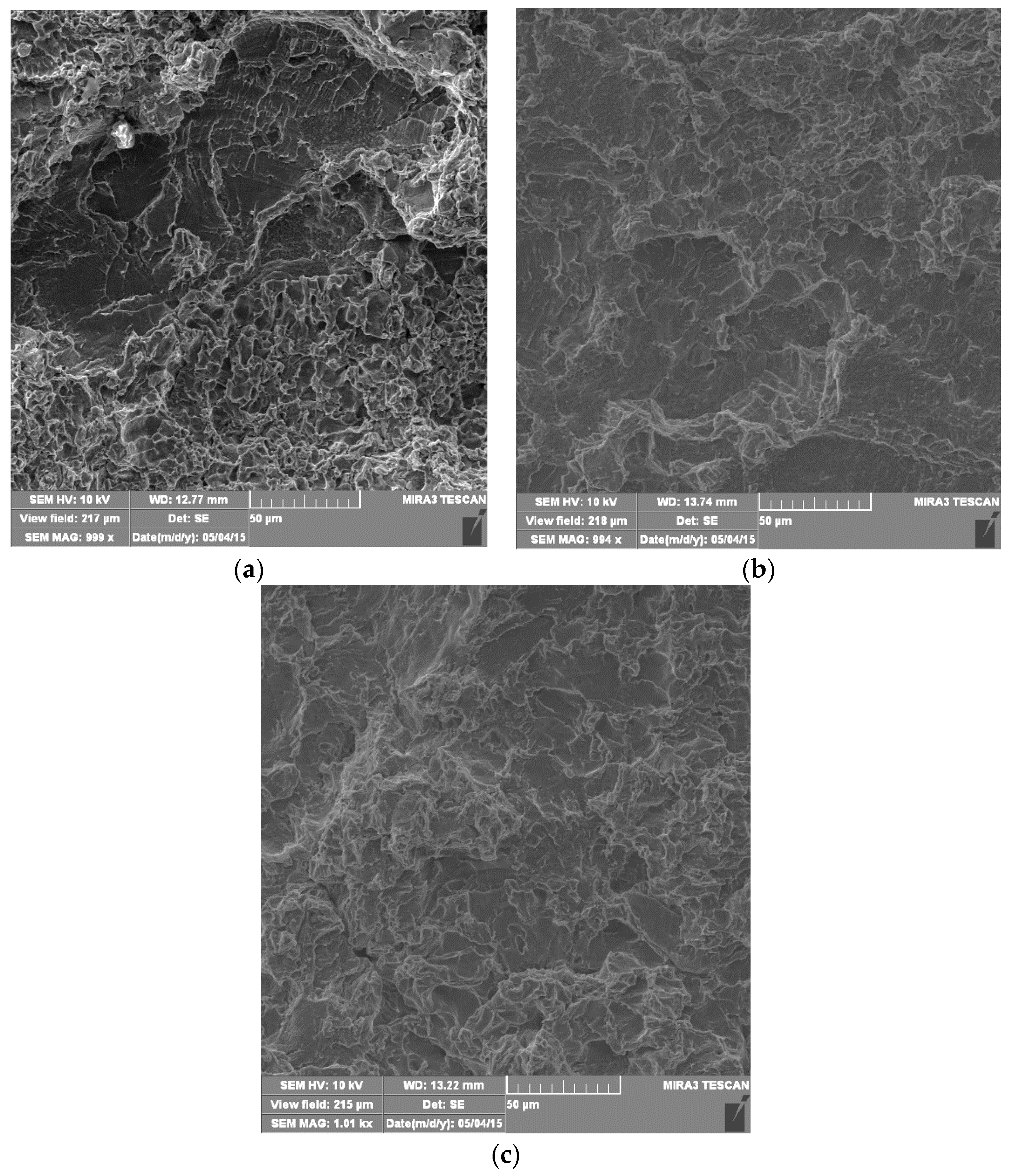
4.4. Morphology of Damaged Surfaces
5. Conclusions
Author Contributions
Funding
Acknowledgments
Conflicts of Interest
References
- Prokić-Cvetković, R.; Kastelec-Macura, S.; Milosavljević, A.; Popović, O.; Burzić, M. The effect of shielding gas composition on the toughness crack growth parameters of AlMg4,5Mn weld metals. J. Min. Metall. B Metall. 2010, 46, 193–202. [Google Scholar] [CrossRef]
- Jang, K.C.; Kuk, J.M. Welding and environmetal test condition effect in weldability and strenght of Al alloy. J. Mater. Process. Technol. 2005, 164–165, 1038–1045. [Google Scholar] [CrossRef]
- Pickens, J.R.; Gordon, J.R. Green, The effect of loading mode on the stress corrosion cracking of aluminium alloy 5083. Met. Trans. A 1983, 14, 925–930. [Google Scholar] [CrossRef]
- Baer, D.R.; Windisch, C.F. Influence of Mg on the corrosion of Al. J. Vac. Sci. Technol. A Vac. Surf. Film. 2000, 18, 131–136. [Google Scholar] [CrossRef]
- Mathers, G. The Welding of Aluminium and Its Alloys; Elsevier: Cambridge, UK, 2003. [Google Scholar]
- Zaidi, M.A.; Sheppard, T. Effects of high temperature soak and cooling rate on recrystalization behaviour of two Al-Mg alloys (AA5252 and AA5454). Met. Technol. 1984, 11, 313–319. [Google Scholar] [CrossRef]
- Reddy, G.M.; Mukhopadhyay, A.K.; Rao, A.S. Influence of scandium on weldability of 7010 aluminium alloy. Sci. Technol. Weld. Join. 2005, 10, 432–441. [Google Scholar] [CrossRef]
- Katsas, S.; Dashwood, R.; Grimes, G.; Jackson, M.; Todd, G. Dynamic recrystallization and superplasticity in pure aluminium with zirconium addition. Mater. Sci. Eng. A 2007, 444, 291–297. [Google Scholar] [CrossRef]
- Robinson, J.S.; Liu, T.Y.; Khan, A.K.; Pomeroy, M.J. Influence of processing on the properties of the aluminium alloy 2025 with a zirconium addition. J. Mater. Process. Technol. 2009, 209, 3069–3078. [Google Scholar] [CrossRef]
- Yarmuch, M.A.R.; Patchet, B.M. Variable AC polarity GTAW Fusion Behaviour in 5083 Aluminium. Weld. J. N. Y. 2007, 86, 196–200. [Google Scholar]
- Facts About Aluminium Welding’; AGA Gas AB SKG-203, Sweden, Member of the Linde Gas Group. 1996. Available online: www.aga.se (accessed on 17 May 2023).
- Aesh, M.A. Optimization of weld bead dimensions in GTAW of aluminium-magnesium alloy. Mater. Manufact. Process. 2001, 16, 725–736. [Google Scholar] [CrossRef]
- Quinn, T.P. Process Sensitivity of GMAW: Aluminium vs. Steel. Weld. J. 2007, 81, 55–60. [Google Scholar]
- Praveen, P.; Kang, M.J. Advancements in pulse gas metal arc welding. Mater. Process. Technol. 2005, 164–165, 1113–1119. [Google Scholar] [CrossRef]
- Kang, B.Y.; Yarlagadda, K.D.V. Prasad, Characteristics of alternate supply of shielding gases in GMA welding. J. Mater. Process. Technol. 2009, 209, 4716–4721. [Google Scholar] [CrossRef]
- Li, Y.; Yang, S.; Peng, Z.; Wang, Z.; Gao, Z. Microstructure, Fatigue Properties and Stress Concentration Analysis of 6005 Aluminum Alloy MIG Welded Lap Joint. Materials 2022, 15, 7729. [Google Scholar] [CrossRef] [PubMed]
- Dudzik, K.; Czechowski, M. The Cracking of Al-Mg Alloys Welded by MIG and FSW under Slow Strain Rating. Materials 2023, 16, 2643. [Google Scholar] [CrossRef] [PubMed]
- Sven-Frithjof Goecke. Auswirkungen von Aktivgaszumischungen im vpm—Bereich zu Argon auf das MIG-impulsschweisen von Aluminium. Ph.D. Thesis, Technische Universität Berlin, Berlin, Germany, 2004.
- Kastelec-Macura, S.; Prokić Cvetković, R.; Jovičić, R.; Popović, O.; Burzić, M. Porosity of welded joints of AlMg4.5Mn alloy. Struct. Integr. Life 2008, 8, 114–120. [Google Scholar]
- Buyukyildirim, G. Investigation of Effects of Shielding Gas Mixture on Fracture Resistance of AlMg4.5Mn Alloy Welded Joints. Ph.D. Thesis, Univeristy of Belgarde, Beograd, Serbia, 2021. [Google Scholar]
- Prokić Cvetković, R.; Popović, O.; Radović Lj Sedmak, A.; Cvetković, I. Fracture Behavior of AlMg4.5Mn Weld Metal at Different Temperatures under Impact Loading. Sustainability 2023, 15, 1550. [Google Scholar] [CrossRef]
- Buyukyildirim, G.; Sedmak, A.; Prokic-Cvetkovic, R.; Popovic, O.; Jovicic, R.; Bulatovic, S. The effect of shielding gas on the toughness of AlMg4.5Mn weld metals made by GMAW. FME Trans. 2011, 39, 127–132. [Google Scholar]
- Chang, J.C.; Chuang, T.H. Stress-corrosion cracking susceptibility of the superplastically formed 5083 aluminum alloy in 3.5 pct NaCl solution. Metall. Mater. Trans. A 1999, 30, 3191–3199. [Google Scholar] [CrossRef]
- Popović, M.; Romhanji, E. Stress corrosion cracking susceptibility of Al–Mg alloy sheet with high Mg content. J. Mater. Process. Technol. 2002, 125–126, 275–280. [Google Scholar] [CrossRef]
- Hammitt, F.G. Cavitation and Multiphase Flow Phenomena; McGraw-Hill: New York, NY, USA, 1980. [Google Scholar]
- Dojčinović, M.; Arsić, M.; Bošnjak, S.; Murariu, A.; Malešević, Z. Cavitation resistance of turbine runner blades at the hydropower plant ‘Djerdap’. Struct. Integr. Life 2017, 17, 55–60. [Google Scholar]
- Istrate, D.; Sbârcea, B.-G.; Demian, A.M.; Buzatu, A.D.; Salcianu, L.; Bordeasu, I.; Micu, L.M.; Ghera, C.; Florea, B.; Ghiban, B. Correlation between Mechanical Properties—Structural Characteristics and Cavitation Resistance of Cast Aluminum Alloy Type 5083. Crystals 2022, 12, 1538. [Google Scholar] [CrossRef]
- Mitelea, I.; Bordeașu, I.; Frant, F.; Uțu, I.-D.; Crăciunescu, C.M.; Ghera, C. Cavitation Erosion Characteristics of the EN AW-6082 Aluminum Alloy by TIG Surface Remelting. Materials 2023, 16, 2563. [Google Scholar] [CrossRef] [PubMed]
- ASTM G32; Standard Test Method for Cavitation Erosion Using Vibratory Apparatus. ASTM International: West Conshohocken, PA, USA, 2010.


| Shielding Gas | ΔKth, MPa∙m1/2 | Coefficient C | Coefficient m | da/dN, m/cyc ΔK = 7 MPa∙m1/2 |
|---|---|---|---|---|
| Ar | 2.88 | 4.44 × 10⁻¹⁰ | 3.86 | 6.87 × 10⁻⁷ |
| Ar + 0.0307%O2 | 2.83 | 4.17 × 10⁻¹⁰ | 3.81 | 8.12 × 10⁻⁷ |
| Ar + 48%He + 0.0290%O2 | 3.02 | 1.05 × 10⁻¹⁰ | 4.07 | 2.89 × 10⁻⁷ |
| Element | Si | Fe | Cu | Mn | Mg | Zn | Cr | Ti |
|---|---|---|---|---|---|---|---|---|
| mass % | 0.13 | 0.21 | 0.04 | 0.66 | 3.95 | 0.03 | 0.06 | 0.025 |
| Tensile Strength Rm (MPa) | Yield Strength R0.2 (MPa) | Elongation A (%) | Total Impact Energy (J) | |
|---|---|---|---|---|
| Rolling direction | 293 | 133 | 25 | 41 |
| Transverse direction | 304 | 143 | 24 | 32 |
| Element | Si | Fe | Cu | Mn | Mg | Zn | Cr | Ti | Zr |
|---|---|---|---|---|---|---|---|---|---|
| mass % | 0.07 | 0.21 | 0.01 | 0.71 | 4.6 | 0.02 | 0.07 | 0.09 | 0.11 |
| Element | Si | Fe | Cu | Mn | Mg | Zn | Cr | Ti | Others | |
|---|---|---|---|---|---|---|---|---|---|---|
| Each | Total | |||||||||
| mass % | <0.40 | <0.40 | <0.10 | 0.5–1.0 | 4.3–5.2 | <0.25 | 0.05–0.25 | 0.15 | <0.05 | <0.15 |
| Process | I (A) | U (V) | Vz (cm/min) | Q (kJ/cm) |
|---|---|---|---|---|
| GTAW | 215–220 | 20–22 | 11–15 | 19.4–23.5 |
| GMAW | 160–170 | 20–22 | 27–32 | 7.0–7.1 |
| GTAW | GMAW | |||||
|---|---|---|---|---|---|---|
| Face | Center | Root | Face | Center | Root | |
| BM | 74.0 | 78.6 | ||||
| 74.4 | 67.3 | 71.3 | 79.8 | 72.3 | 77.9 | |
| 72.2 | 70.1 | 70.6 | 80.2 | 78.4 | 81.6 | |
| 71.6 | 68.5 | 73.2 | 76.2 | 72.7 | 83.1 | |
| 72.0 | 68.6 | 72.0 | 81.1 | 74.8 | 82.1 | |
| 73.5 | 74.9 | 72.2 | 80.3 | 73.9 | 83.3 | |
| HAZ | 75.5 | 76.6 | 70.9 | 79.9 | 78.6 | 81.5 |
| WM | 74.7 | 67.1 | 69.3 | 74.0 | 78.2 | 81.7 |
| 73.4 | 76.3 | 75.1 | 73.6 | 82.2 | 84.3 | |
| 74.6 | 74.4 | 77.3 | 82.6 | 70.8 | 84.5 | |
| 73.4 | 76.8 | 71.1 | 79.1 | 79.2 | 79.1 | |
| 74.7 | 78.5 | 74.1 | 75.1 | 77.4 | 84.1 | |
| 73.3 | 73.4 | 76.2 | 70.0 | 74.3 | 81.3 | |
| 73.3 | 75.2 | 74.8 | 71.2 | 75.2 | 88.5 | |
| 73.1 | 71.4 | 75.1 | 76.5 | 77.2 | 81.8 | |
| HAZ | 74.3 | 67.5 | 72.3 | 71.3 | 74.2 | 79.4 |
| BM | 71.1 | 68.7 | 71.1 | 73.1 | 70.4 | 78.8 |
| 71.4 | 70.7 | 71.8 | 76.1 | 71.3 | 79.6 | |
| 71.7 | 74.3 | 69.0 | 79.4 | 72.3 | 82.1 | |
| 74.2 | 72.5 | 73.8 | 78.5 | 78.5 | 82.6 | |
| 73.4 | 76.8 | |||||
| Sample | Total Mass Loss (mg) | Cavitation Rates (mg/min) |
|---|---|---|
| Base metal—AlMg4.5Mn | 51.3 | 0.285 |
| Weld metal—GTAW | 87.9 | 0.488 |
| Weld metal—GMAW | 64.5 | 0.358 |
Disclaimer/Publisher’s Note: The statements, opinions and data contained in all publications are solely those of the individual author(s) and contributor(s) and not of MDPI and/or the editor(s). MDPI and/or the editor(s) disclaim responsibility for any injury to people or property resulting from any ideas, methods, instructions or products referred to in the content. |
© 2023 by the authors. Licensee MDPI, Basel, Switzerland. This article is an open access article distributed under the terms and conditions of the Creative Commons Attribution (CC BY) license (https://creativecommons.org/licenses/by/4.0/).
Share and Cite
Dojčinović, M.; Prokić Cvetković, R.; Sedmak, A.; Popović, O.; Cvetković, I.; Radu, D. Effect of Shielding Gas Arc Welding Process on Cavitation Resistance of Welded Joints of AlMg4.5Mn Alloy. Materials 2023, 16, 4781. https://doi.org/10.3390/ma16134781
Dojčinović M, Prokić Cvetković R, Sedmak A, Popović O, Cvetković I, Radu D. Effect of Shielding Gas Arc Welding Process on Cavitation Resistance of Welded Joints of AlMg4.5Mn Alloy. Materials. 2023; 16(13):4781. https://doi.org/10.3390/ma16134781
Chicago/Turabian StyleDojčinović, Marina, Radica Prokić Cvetković, Aleksandar Sedmak, Olivera Popović, Ivana Cvetković, and Dorin Radu. 2023. "Effect of Shielding Gas Arc Welding Process on Cavitation Resistance of Welded Joints of AlMg4.5Mn Alloy" Materials 16, no. 13: 4781. https://doi.org/10.3390/ma16134781