1. Introduction
Concrete jacketing is an effective seismic retrofit method to improve strength and rigidity by enlarging the cross-section of reinforced concrete columns. The seismic performance of a retrofitted member with a concrete jacket is affected by the reinforcement in the jacketing section, the compressive strength of concrete, and the bonding between the old section and the jacketing section. Therefore, recent studies have been conducted on seismic hooks and steel wire mesh (SWM) to improve the shear performance of the jacketing section and on the use of dowels to constrain the jacketing section and the old section [
1,
2,
3]. Many studies focused on improving the strength of the jacketing section using ultra-high-performance fiber-reinforced concrete (UHPFRC) have been conducted [
4,
5,
6,
7]. UHPFRC can show excellent strength, ductility and durability by lowering the water-binder ratio (W/B) by 20% and mixing high-powder admixtures and high-strength steel fibers. The thickness of the jacketing section can be reduced when using such a high-performance material, and the strength and ductility of the retrofitted members were effectively improved. However, UHPFRC, with less water, has a large amount of admixture and no coarse aggregate compared to conventional concrete, which results in high self-shrinkage and a high risk of shrinkage cracking. In a previous study [
8], a new hybrid concrete jacketing method was proposed with non-shrinkage mortar in which shrinkage was suppressed by adding an anti-shrinkage admixture. Steel fiber was mixed into the non-shrinkage mortar to enhance the strength of the jacketing section. Conventional concrete jacketing methods use a lot of reinforcement (such as dowels or cross ties) to improve bond capacity, but this reduces workability. Hybrid concrete jacketing methods involve steel wire mesh (SWM) and steel grid reinforcement (SGR). The welded SWM is attached to the surface of the old section to improve the adhesion between the old section and the jacketing section. This makes it possible to omit the process of chipping the concrete surface, thereby improving workability compared to the conventional concrete jacketing method.
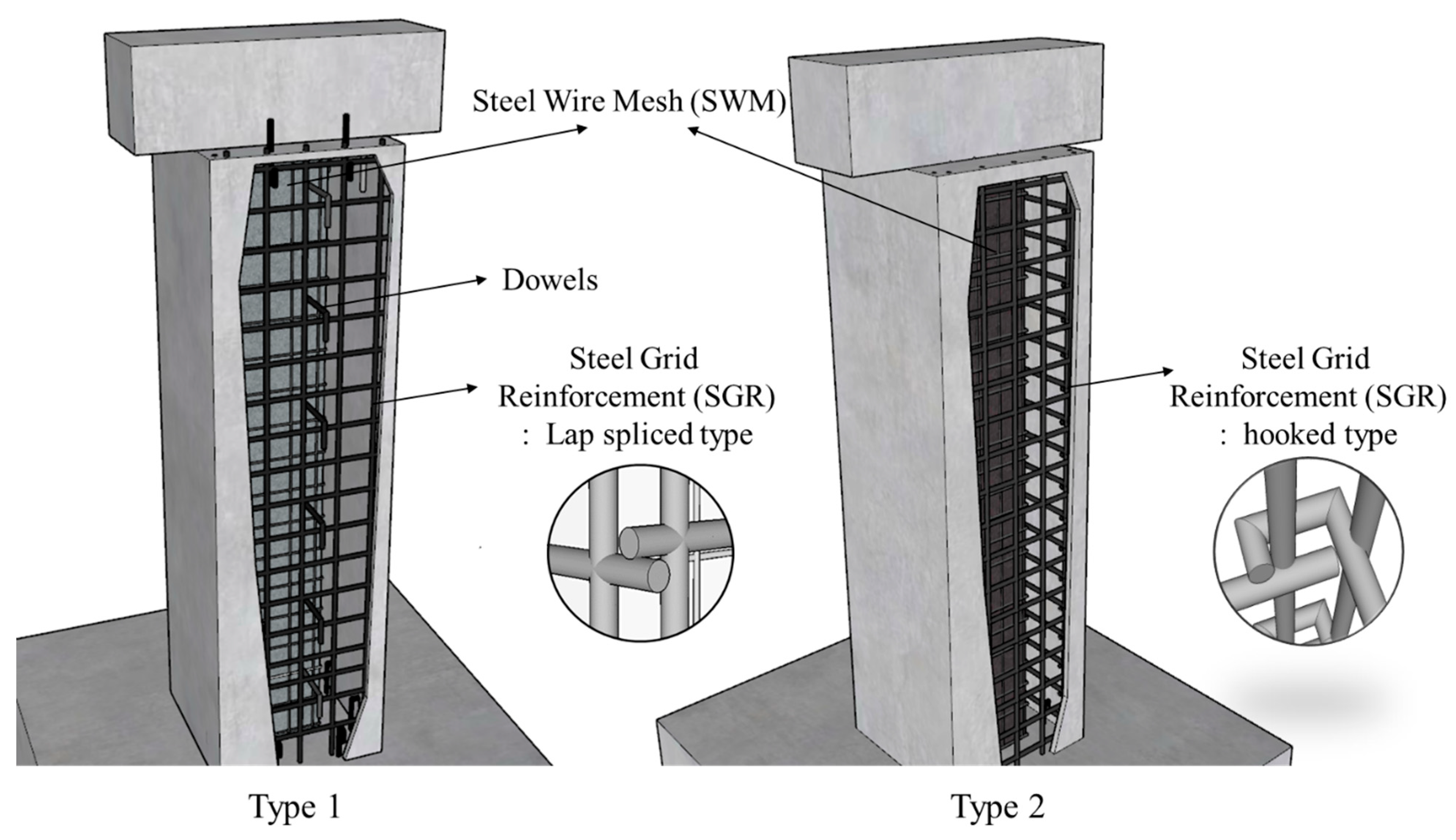
The hybrid concrete jacketing method is divided into two types according to the reinforcement in the jacketing method, as shown in
Figure 1. Type 1 is easy to manufacture as welded reinforcing bar grids, but the confinement is reduced, so a small number of dowels are used to improve the bonding capacity between the old section and the jacketing section. Type 2 is a method involving making a hook at the end of the SGR. As compared to seismically designed transverse reinforcement with 135-degree hooks proposed in the ACI 318-19 standard [
9], this construction is simpler and less hook loosening occurs, so excellent seismic performance can be expected. When seismic retrofitting a reinforced concrete structure with concrete jacketing, the most important factor is whether a slip occurs at the interface between the old section and jacketing section. Slip occurs at the interface between the core and the jacket concrete if the bonding is not properly secured when a load is applied to the reinforced concrete columns, so the seismic performance of the jacketing section is expected to be unacceptable. There are limited published studies on the contact surfaces of reinforced concrete members and jacketing [
6]. Furthermore, when dealing with members having connections, it is important to conduct investigations to identify potential factors that could impact the monolithic behavior, such as slippage [
10,
11,
12,
13]. Psycharis and Mouzakis [
10] examined the effect of dowel diameter, the number of dowels, and the placement of dowels from the edge of the section on the shear behavior of precast members under different loading patterns. The experimental results indicated that the resistance of the connection under cyclic loading was only half of that under monotonic loading, and the thickness of the cover concrete in the dowel installation direction was found to be related to dowel slippage, which was identified as a factor affecting the shear performance. Therefore, this study experimentally analyzed whether the hybrid concrete jacketing method proposed in a previous study [
8] can ensure the appropriate bonding capacity and proposed a shear strength equation for reinforced concrete columns retrofitted with a hybrid concrete jacket.
2. Experimental Program
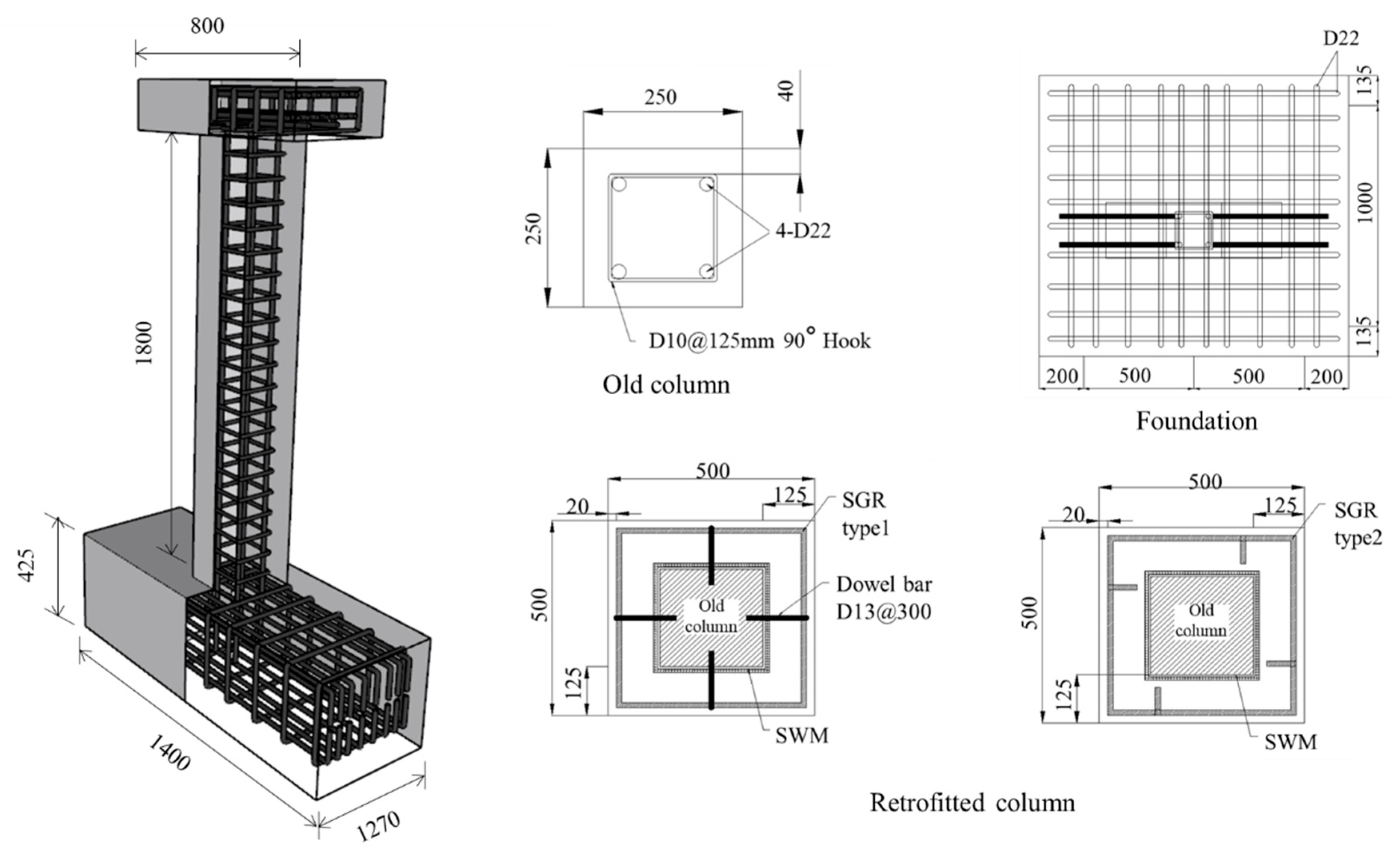
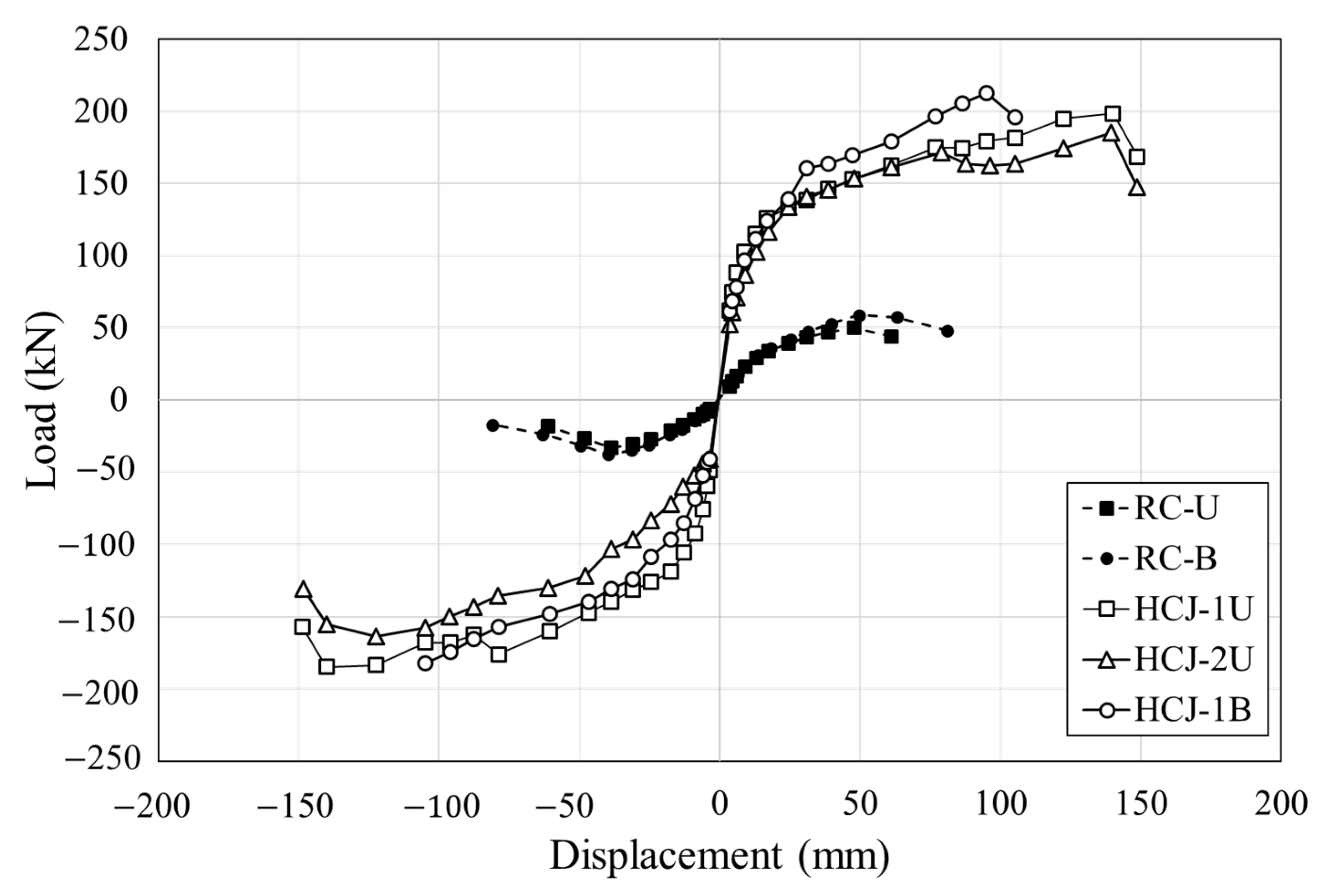
To analyze the seismic performance of the hybrid concrete jacketing method, two test specimens of reinforced concrete columns without seismic design and three specimens retrofitted with hybrid concrete jackets were fabricated and subjected to a cyclic loading test. The details of the specimens are shown in
Figure 2 and
Table 1. The cross-section of the reinforced concrete column without seismic design was 250 mm × 250 mm, and the height was 1800 mm. For the jacketing section, 4 sides were retrofitted with a thickness of 125 mm by referring to the design method for the concrete jacketing section presented in Pennelis and Kappos [
14]. The upper beam is for applying the axial and lateral load, the cross-section was 250 mm × 250 mm, and the length was 800 mm. The specimen was cast on a foundation that was 1400 mm × 1270 mm × 450 mm. The foundation was fastened to a strong floor through high-tensile bolts. The reinforcement was designed in accordance with the ACI 318-19 design standard. Four deformed bars with diameters of 22 mm and 90-degree closed external stirrups with diameters of 10 mm were placed at spacings of 125 mm in the column. The SWM was placed on the jacketing section using steel wire with a diameter of 10 mm, and the SGR, which served as the longitudinal bars and hoops of the column, was manufactured off-site using deformed reinforcing bars with diameters of 13 mm. The compressive strength of the concrete and the non-shrinkage mortar cast on the jacketing section were 24 MPa and 30 MPa, respectively. The yield strength of reinforcing bars placed in the old column and jacketing section was 400 MPa. In the hybrid concrete jacketing method, a non-shrinkage mortar was mixed with steel fibers to improve the structural performance of retrofitted members. The steel fiber was developed for non-shrinkage mortar and had a diameter of 0.34 mm, a length of 18 mm, and a tensile strength of 1250 MPa. Steel fiber content was designed to be 1.5% to ensure excellent performance and workability according to studies of the effect of steel fiber content on structural performance [
15,
16,
17,
18].
Table 2 summarizes the material properties used in the manufacture of the specimens.
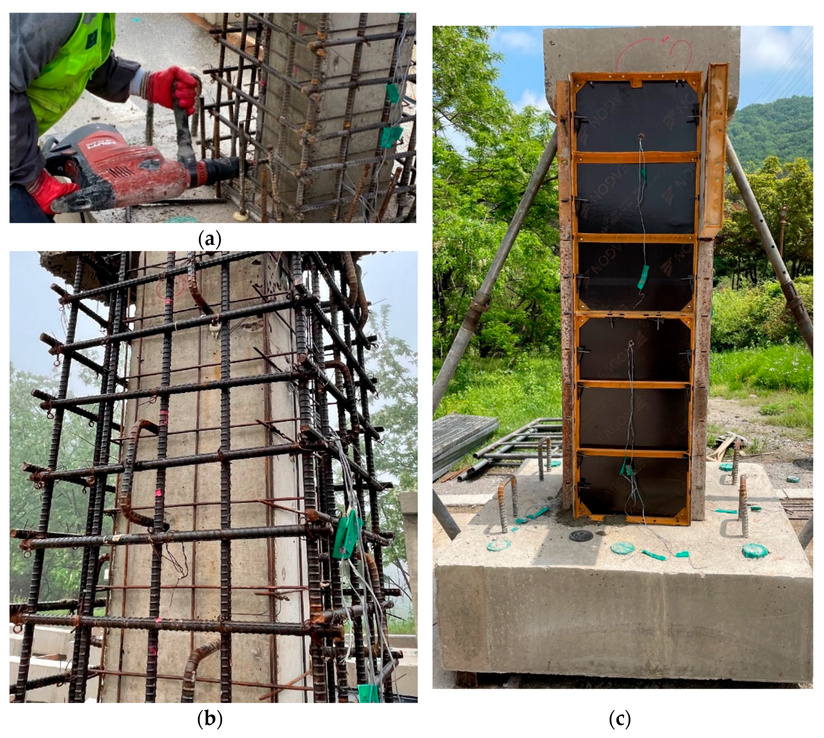
The manufacturing process of the specimens retrofitted with the hybrid concrete jacketing method is presented in
Figure 3. The first step involves wrapping SWM around all four sides of the old column to enhance the bonding capacity between the old column and the jacketing section. The concrete core was fully confined using SWM, and strips of SWM were tightly fastened with steel wires. Subsequently, chemical anchors were installed by drilling the old column to place the SGR or dowel bar. Dowel bars were not used in the case of the specimen with Type 2 detail. Finally, a formwork was constructed on the jacketing section and non-shrinkage mortar mixed with steel fibers was poured. Chipping is a crucial process in conventional concrete jacketing that roughens the section of the old column. However, the hybrid concrete jacketing method improved adhesion performance by bonding SWM to the old column. Therefore, it was possible to omit the chipping process, which generates dust and hinders workability.
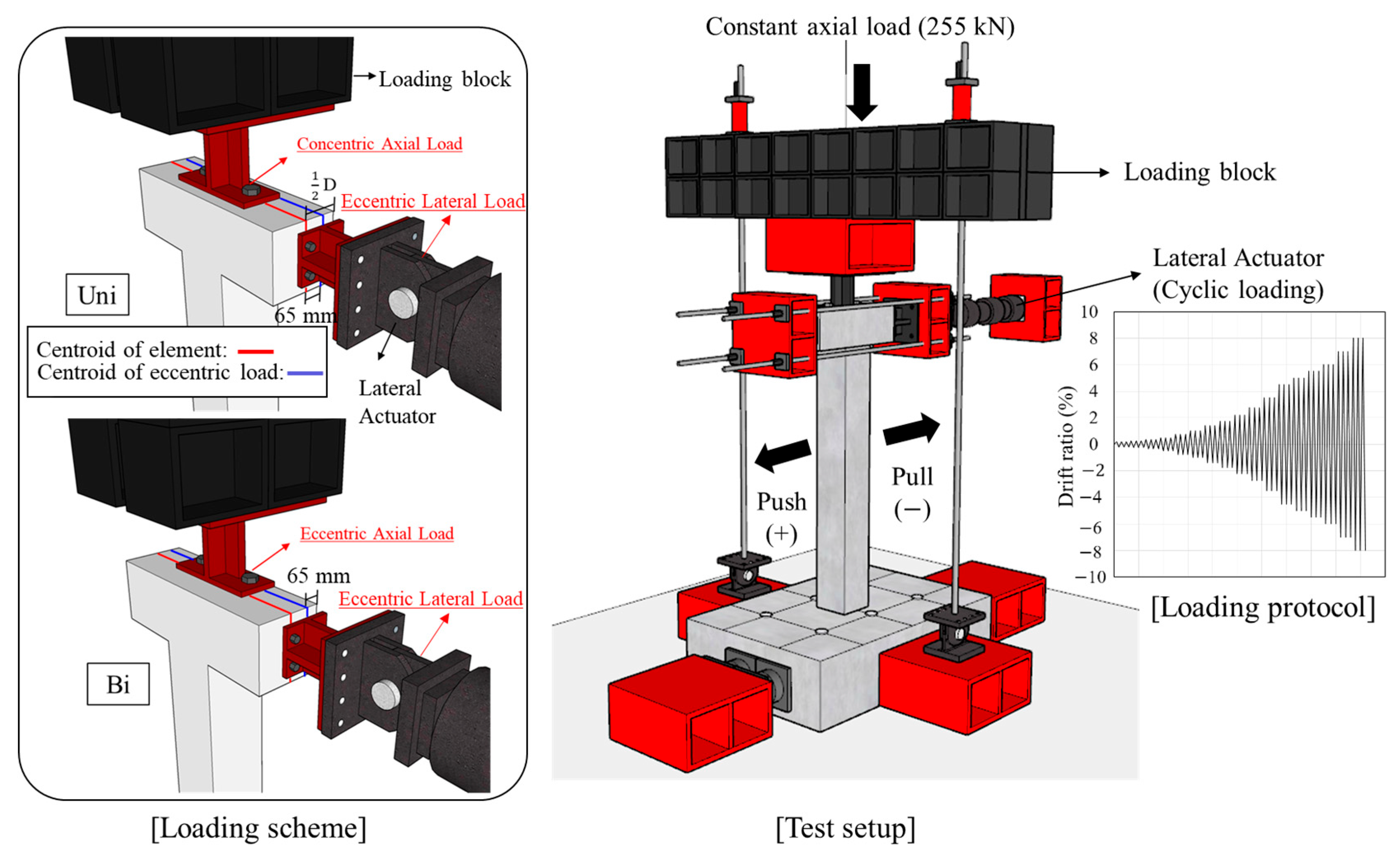
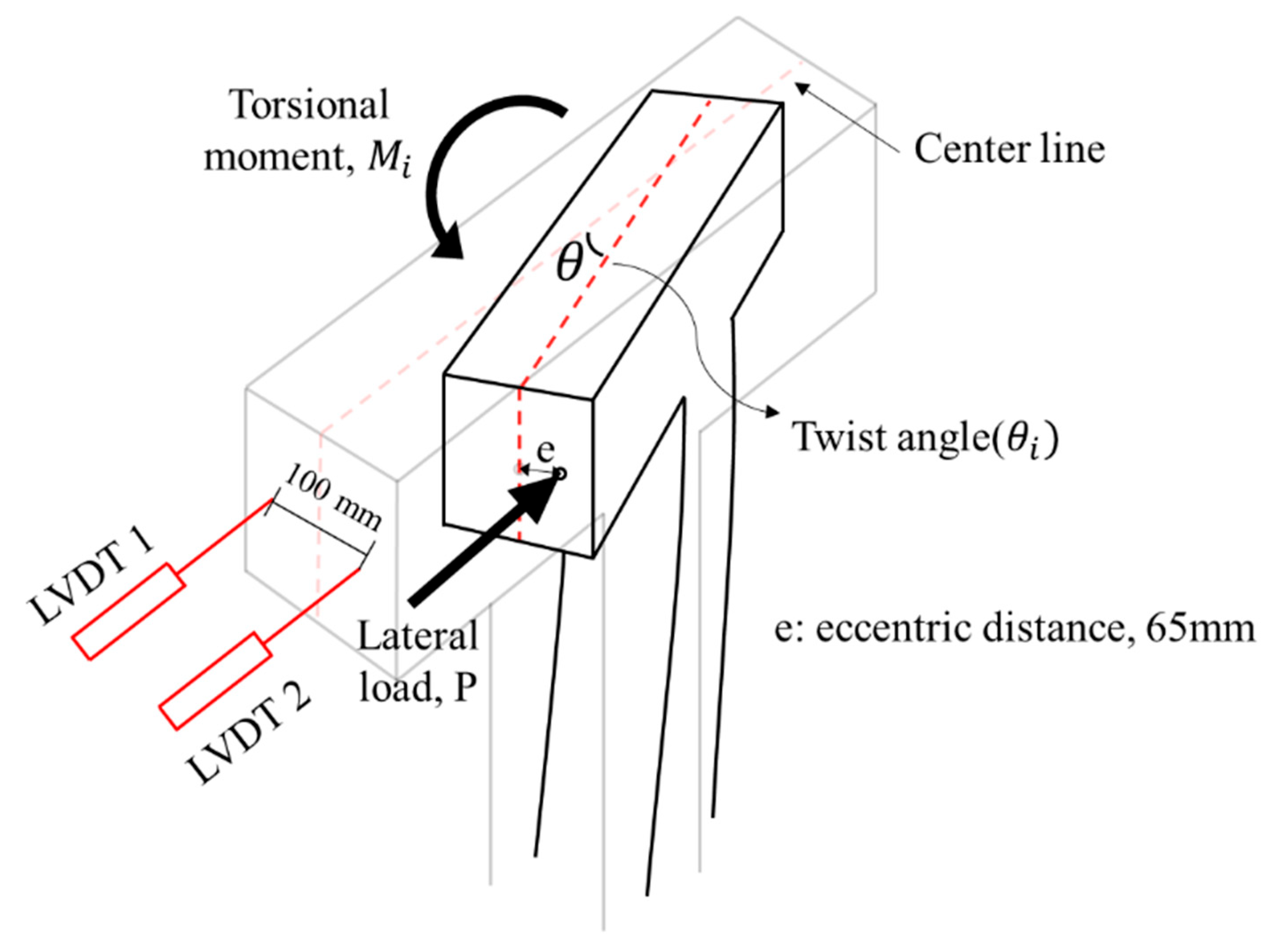
In this study, a cyclic loading test considering axial load, lateral load, and torsional load was conducted to simulate actual seismic load. The test setup and the quasi-static loading protocol are shown in
Figure 4. Details related to the loading setup and protocols are provided in a previous study [
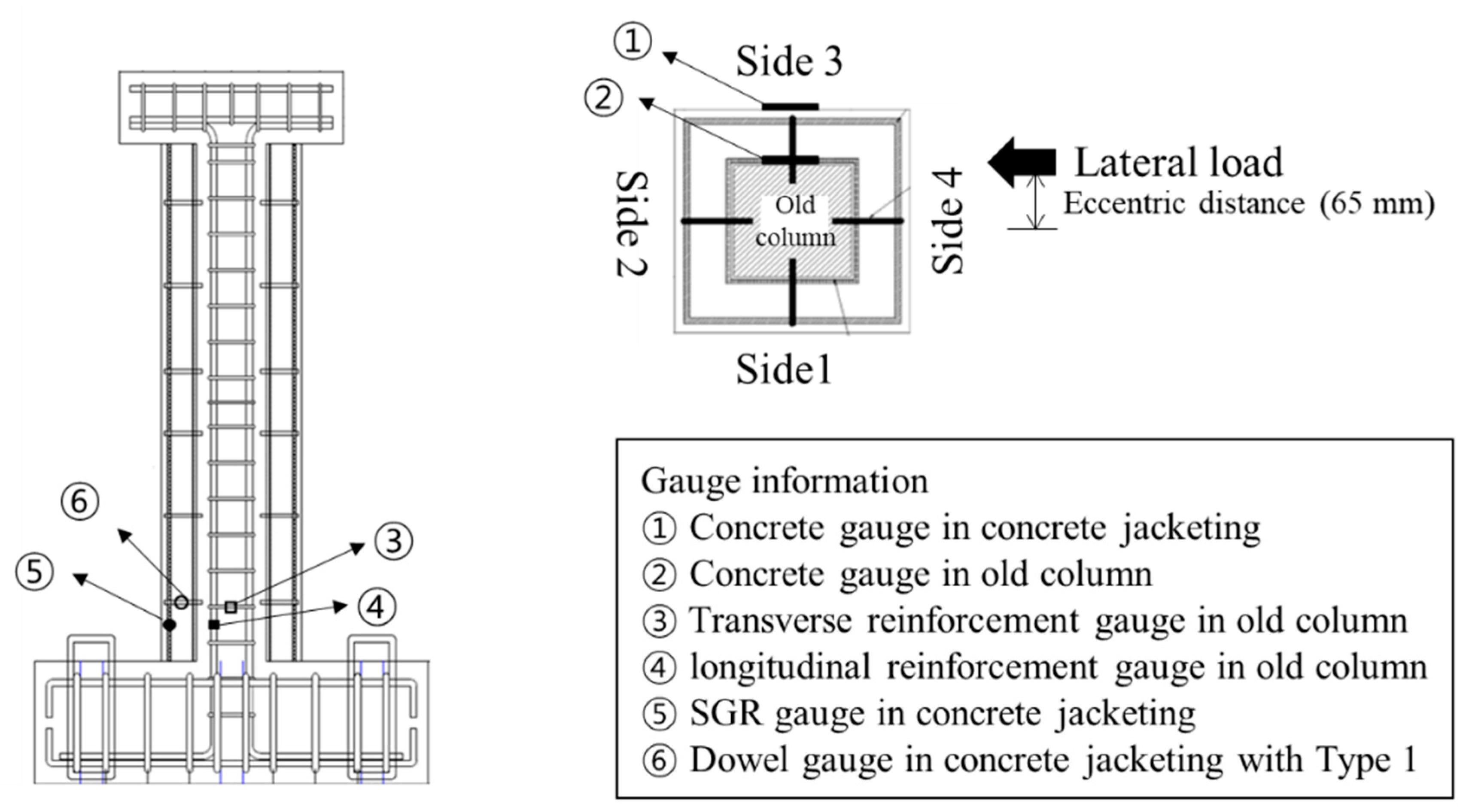
8]. The cyclic lateral load was applied through the horizontal actuator, and it was increased gradually from a drift ratio of 0.2% until the test was terminated. The definition of drift ratio is the ratio of the lateral displacement to the height from the bottom of the column to the loading point. A constant axial load of 255 kN, which is 17% of the axial load capacity, was applied. An eccentric load was applied to generate torsion with single (unidirectional) or multi-directional (bidirectional) loads. When a compressive force is applied at a location beyond the core of a section, tensile stress is induced in addition to compressive stress, and concrete is especially vulnerable to tensile stress. This study induced the tensile stress on the specimens to simulate extreme conditions during an actual earthquake by applying a load at a location beyond the core of a section. An eccentricity of 65 mm was set, considering the core of a section (1/6 of the section dimension for a rectangular section). To measure the strain of steel reinforcement and concrete, strain gauges were installed near the plastic hinge of the column where the damage is expected to be concentrated, as shown in
Figure 5. As shown in
Figure 5, the front sides of the specimen were designated Side 1, and the elevations were classified by naming Sides 2, 3, and 4 in the counterclockwise direction to identify the direction.
4. Proposed Shear Strength Equation
The seismic performance of a concrete jacketed column depends on the bonding of the old concrete and added concrete. If appropriate shear reinforcement is designed in the jacketed section, a column with a concrete jacket should act monolithically under seismic load. Therefore, the shear strength and behavior of a reinforced concrete column retrofitted with concrete jacketing are predicted, considering the jacketed section to be an equivalent monolithic section [
21]. The experimental results confirmed that the SGR of the hybrid concrete jacketing method performed the role of longitudinal reinforcements and hoops. Therefore, the reinforced concrete column retrofitted with hybrid concrete jacketing was an adequately designed shear reinforcement. In the past few decades, the bond-slip model was mainly considered for reinforced concrete strengthened with fiber-reinforced polymer (FRP) to avoid debonding failure. However, recent studies have confirmed that reinforced concrete columns retrofitted with concrete jackets should consider the slip when it takes place along the interfaces between the old section and the jacketing section [
20,
22,
23]. The mechanics of reinforced concrete members retrofitted with a concrete jacket are quite complex. In particular, it is difficult to consider the behavior of the interface between the existing member and the jacket [
23]. In this study, the slip coefficient was experimentally determined as a measure of the bonding capacity between the two sections to assess the behavior of the interface between the concrete jacket and the existing members. It is common to measure the slip coefficient experimentally considering various factors such as the strain, material of the jacket and existing member, friction coefficient, and angle.
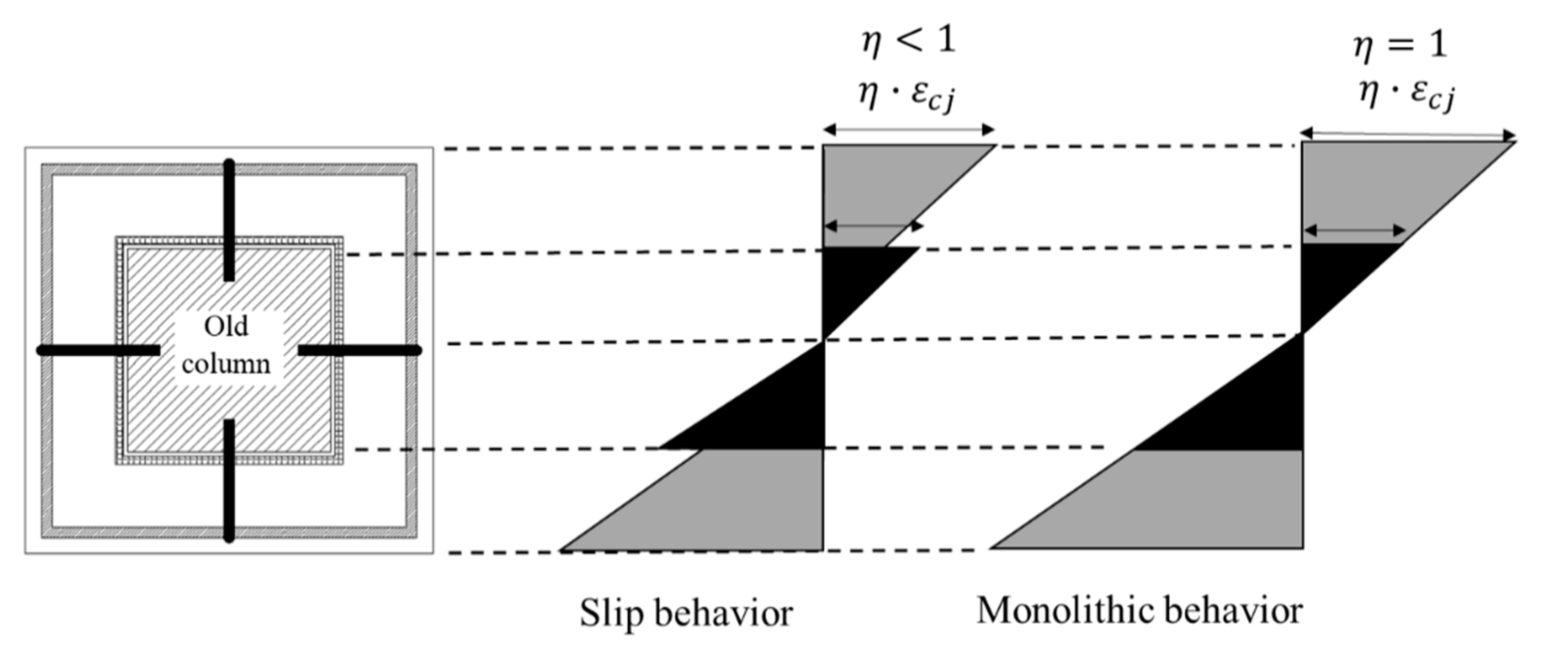
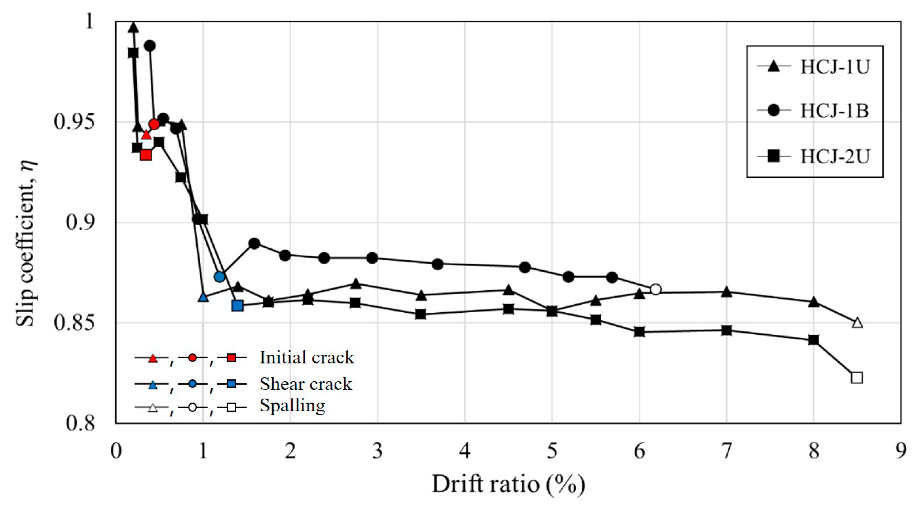
Figure 12 shows the strain profile of the jacketed cross-section. As shown in
Figure 12, the slip coefficient,
, is a value that measures the frictional force between the jacketing section and the existing member. It is an indicator of the strength of the bonding capacity between the two sections. The slip coefficient is one of the most important factors in ensuring safe attachment between the jacket and the existing member in the concrete jacketing method. If the old column is considered to be fully confined due to the confinement provided by the jacket, there is no sliding at the interface between the column and jacket. Therefore, the slip coefficient equals 1.0. On the other hand, in a partially confined column, the slip coefficient is less than 1.0, and the concrete strain of the jacketed section decreases by the ratio of the slip coefficient. This value is usually in the range of 0.8 to 1.0, with a higher value indicating a stronger friction force between the jacket and the existing member.
To obtain the slip coefficient, gauges were used to measure the concrete strain in both the old section and the jacketing section, as shown in
Figure 5. The gauges were placed at the same location in the cross-section of the existing member and the jacketing concrete, as illustrated in
Figure 5. The slip coefficient was calculated based on the difference in concrete strain between the two sections, with a higher value indicating a smaller difference in strain and stronger bonding between the old section and the jacketed concrete section.
Figure 13 depicts the slip coefficients obtained by calculating the difference in strain between the old section and the jacketing section for each drift ratio. At the onset of the experiment, the slip coefficient is approximately 1.0. However, all specimens exhibited a trend of decreasing slip coefficient as the drift ratio increased. This is because the torsion acting on the specimen increased according to the drift ratio. In addition, the slip coefficient decreased rapidly from the initial crack occurrence to the point of shear crack occurrence, and the slip coefficient converged after shear cracking. Bonding between the jacketing section and the old section decreased because torsion causes shear cracks in columns. The slip coefficient did not decrease beyond a certain level since the SWM attached to the old section secured the bonding capacity with the jacketing section. In this paper, the smallest value among the slip coefficients measured in the experiment was considered when calculating shear strength to ensure a conservative design. The slip coefficients for the HCJ-1U, HCJ-1B, and HCJ-2U specimens were verified to be 0.86, 0.88, and 0.82, respectively. Due to the misaligned axes of axial and lateral forces during unidirectional loading, HCJ-1U exhibited a smaller slip coefficient than HCJ-1B because the torsional forces were greater. Nevertheless, the discrepancy in slip coefficient between loading schemes was insignificant at approximately 2%. Since it is not feasible to anticipate the loading scheme under actual seismic loads, a conservative slip coefficient of 0.86 was assigned to Type 1. It should be noted that Type 2 had no dowel (unlike Type 1), and it ensured bonding capacity through the hooked details in SGR. As a result, the slip coefficient of Type 2 decreased compared to that of Type 1, with a value of approximately 95% of Type 1.
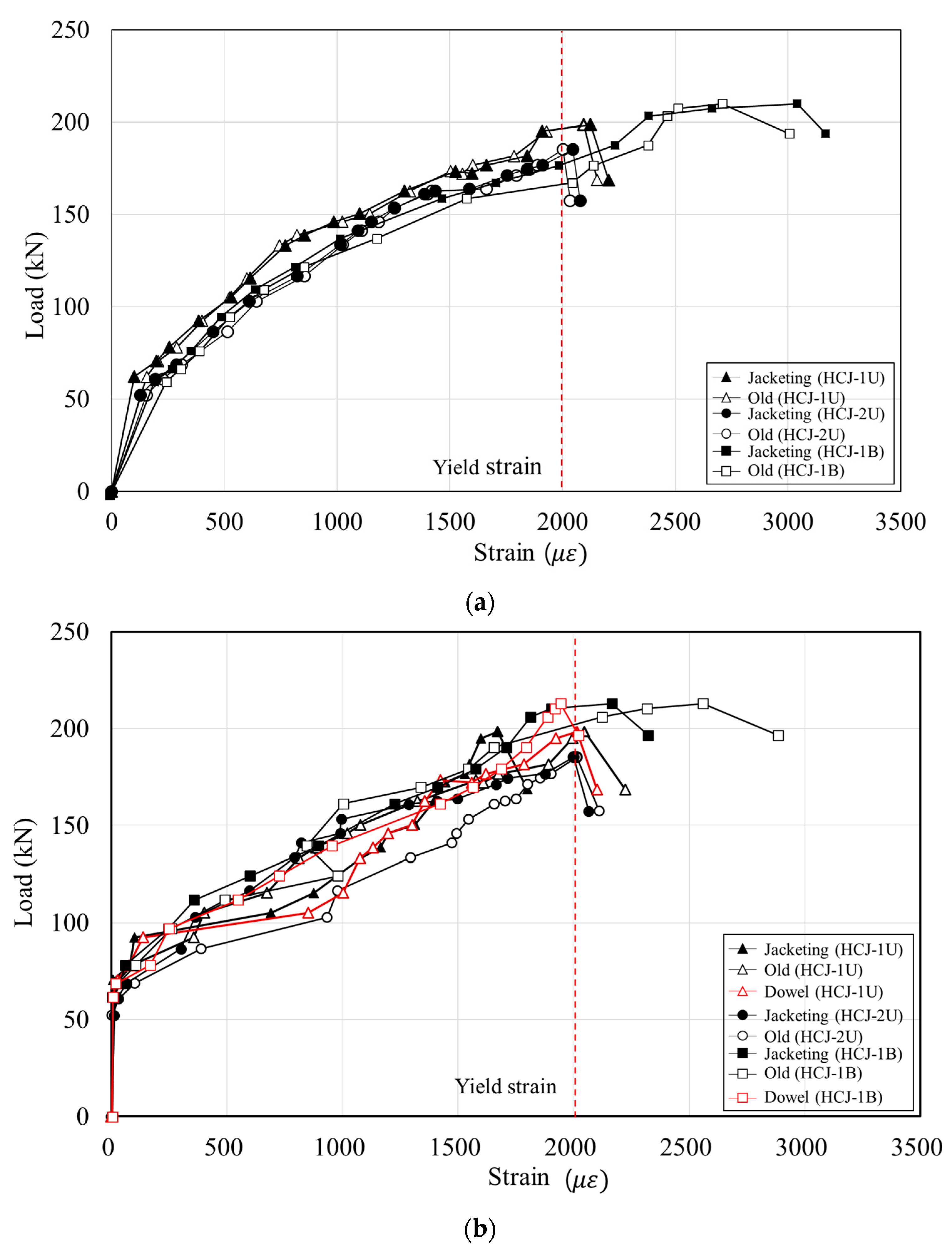
This study proposed a novel concrete jacketing method that employs non-shrinkage mortar for concrete jacketing, with the objective of enhancing workability and alleviating the problem of high self-shrinkage that is typically associated with Ultra-High-Performance Fiber-Reinforced Concrete (UHPFRC). It is important to note that the slip of stirrups in concrete can have a significant impact on the strength and durability of columns, particularly in columns that use mortar. This is due to the relatively smooth surface of mortar, which can lead to increased stirrup slippage compared to concrete columns. As depicted in
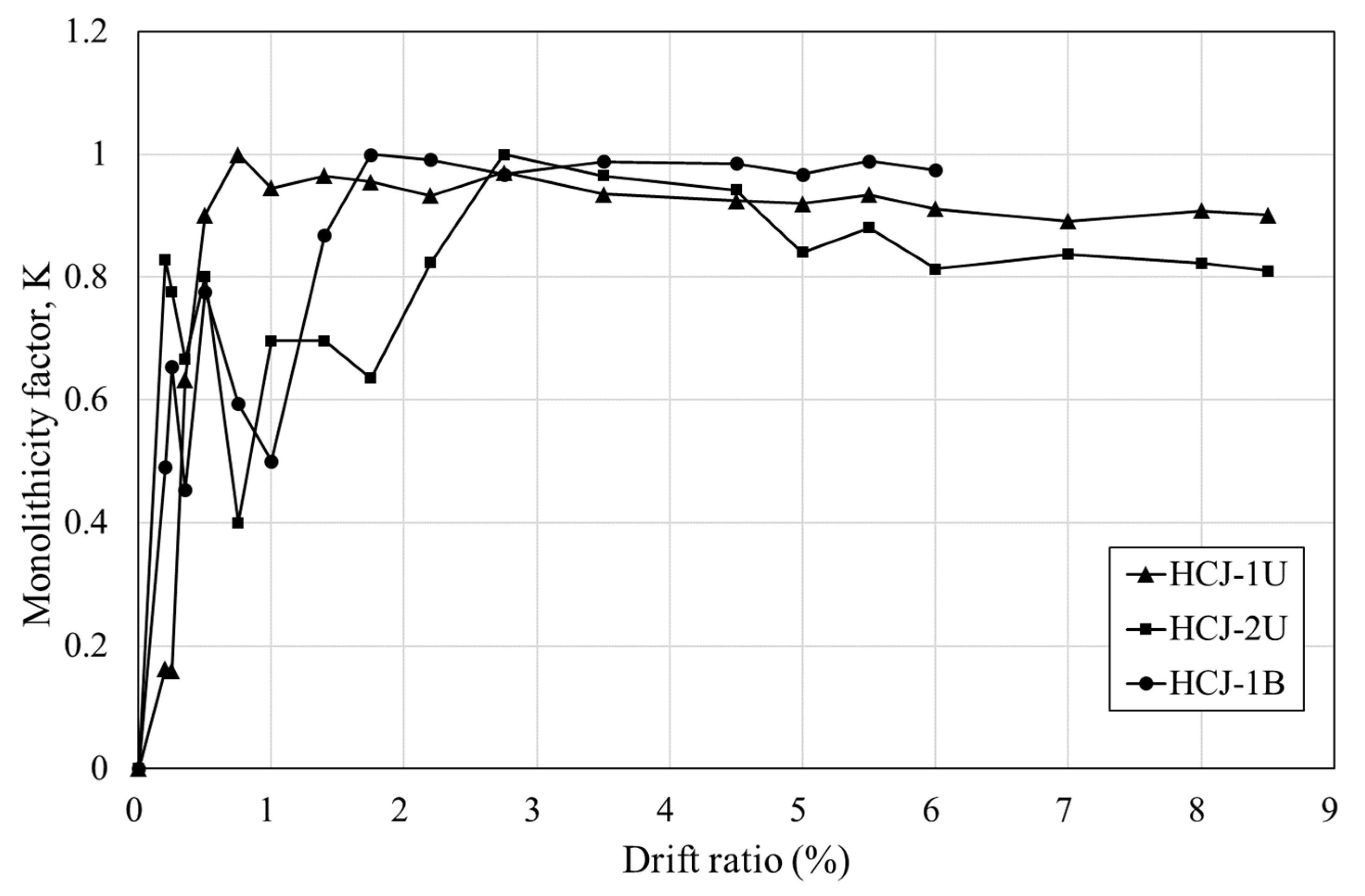
Figure 10, the strain patterns of the stirrups in the old and jacketing sections were similar. Nonetheless, slippage between the mortar and stirrup could potentially occur in the jacketing section, thereby compromising the shear performance of the stirrup. Consequently, the disparity in strains between the old and jacketing sections of the stirrup was analyzed, and this factor was accounted for in the evaluation of the shear strength of the stirrup in the jacketing section. The monolithicity factor (K) was introduced as a measure of bonding performance in the concrete jacketing method to investigate the reduction in shear capacity resulting from stirrup slippage within the jacketing section. The K factor is defined as the ratio of the response index of composite members to the response index of monolithic members with an identical geometry [
23]. In this study, a comparison between a monolithic concrete column and a jacketed concrete column having identical geometries was not carried out. Nevertheless, the stirrup of the existing concrete column and that of the concrete jacket were designed to exhibit equivalent shear performance. Hence, the monolithicity factor was determined by computing the ratio of the stirrup strain in the jacketing section to that in the old section. The monolithicity factor was subsequently normalized to a maximum value of 1, and the results are presented in
Figure 14.
During the initial stage of the experiment, the load was carried by the stirrup in the old column until yielding occurred, after which the stirrup within the jackets began to carry the load with an increase in load. Consequently, the monolithicity factor K, which denotes the ratio of stirrup strain in the jacketing section to that in the old section, gradually increased and approached unity in the early stages of the experiment. However, the load carried by the stirrup within the jacketing section increased as the torsional load increased, causing a reduction in friction between the stirrup and mortar in the jacket, resulting in a decrease in K. This phenomenon was observed consistently in all specimens, and K approached a constant value at the maximum load. The loading scheme was closely related to K, and the values of K at the failure for HCJ-1U, HCJ-2U, and HCJ-1B were 0.9, 0.82, and 0.97, respectively. Unidirectional loading led to an increase in torsional load, a reduction in bonding capacity between the stirrup and mortar within the jacketing section, and an increase in shear stress in the jacketing section. Moreover, Type 2 showed a greater decrease in bonding capacity between the stirrup and mortar within the jacketing section than Type 1 because no dowel was used to connect the old and jacketing sections, resulting in more sliding between the two sections and an increase in shear strength within the jacket.
In this study, the shear strength of concrete and stirrup was estimated using the ACI 318-19 design criteria as shown in Equations (3)–(5).
Here, is the gross area of the concrete section, and s are the area and spacing of shear reinforcement, is the web width of the cross-section, d is the distance from extreme compression fiber to the centroid of longitudinal reinforcement, is the compressive strength of the concrete, is the yield strength of the stirrup, is the factored axial force acting on the cross-section of the column, and λ represents the influence of lightweight concrete.
The shear strength equation of the reinforced concrete column retrofitted with hybrid concrete jacketing was proposed as shown in Equations (6)–(8). If slippage occurs between the old and jacketing sections, both sections may not fully exhibit their shear performance under seismic loads. To mitigate this issue, this study proposed a slip coefficient for each type of hybrid concrete jacketing method that considers the level of slippage between the old and jacketing sections based on experimental results. As a result, the contribution of concrete was estimated by multiplying the sum of the shear contributions of the old and jacketed sections by the slip coefficient to evaluate the shear strength of a reinforced concrete column retrofitted with hybrid concrete jacketing. The hybrid concrete jacketing method used mortar instead of concrete in the jacketing section, which can result in increased slip between the reinforcement steel and mortar due to the absence of coarse aggregate. Therefore, the reduction in stirrup shear capacity due to a slip between the mortar and the stirrup should be considered. The shear strength of the stirrup in the jacketing section was determined by multiplying the shear strength of the stirrup in the existing reinforced concrete column by a monolithicity factor, which is a reduction factor. The variable n in Equation (8) indicates the number of pertinent entities drawn from the subsequent options:
- (1)
When a unidirectional load is applied.
- (2)
When no additional steel, such as dowels, is provided to enhance the bonding performance between the old section and the jacketing section.
The experimentally obtained shear strengths were compared with those predicted by the ACI 318 design code and the proposed equation presented in
Table 4. The shear strength evaluated based on the ACI 318-19 and the proposed equations neglect the loading scheme applied to the reinforced concrete column. Huang et al. [
19] conducted cyclic loading tests on nine reinforced concrete columns with variable load patterns and found that the shear strength of the columns decreased by approximately 60% when subjected to an eccentric lateral force as compared to the case where no eccentricity was present. Accordingly, this study compared the experimental results and the shear strength determined by the design criteria and proposed equations, with the latter being reduced to 60% of their calculated values. The ACI 318 design code, which does not consider slip, was found to overestimate the experimental results by approximately 23%. This was attributed to excessive deformation caused by seismic loads acting on the column, which led to a slip between the old and jacketing sections of the column. However, the proposed equation calculated the shear strength of reinforced concrete columns retrofitted with concrete jackets in detail by considering slip as a factor. The slip coefficient and monolithicity factor were derived by measuring the strain of the concrete and stirrups in the old and jacketing sections and considering the strength reduction due to slip. The proposed equation yielded a shear strength ratio of approximately 1.1 to that obtained from the experiment for all specimens, indicating a conservative prediction. Therefore, the proposed equation was deemed capable of accurately predicting the shear strength of reinforced concrete columns retrofitted with concrete jackets, mitigating the issue of overestimation observed in the existing design code.


