
Additive Manufacturing as a Solution to Challenges Associated with Heat Pipe Production


Abstract
:1. Introduction
- Difficulties in the integration of the HP into the electronic chassis elements or with the heat source that enable direct thermal management of the heated devices and decrease its thermal resistance. Part incorporation allows further reduction in weight or material by incorporating HP into another component [2,16,17,18,19,20];
- Frequent deformation and ballooning of flat shape HPs, vapour chamber HPs and flat evaporator loop HPs caused by the elevated internal fluid saturation pressure. This can cause a failure of the thermal contact of the heat source and HP or a loss of the thermal junction between the wick structure and casing. The elevated saturation pressure of the working fluid may deform the envelope shape or porous structure. Such matter requires the very diligent design of the HP and might result in the increase in envelope thickness, increased HP weight or limit the choice of the working fluid [10,24,25,26];
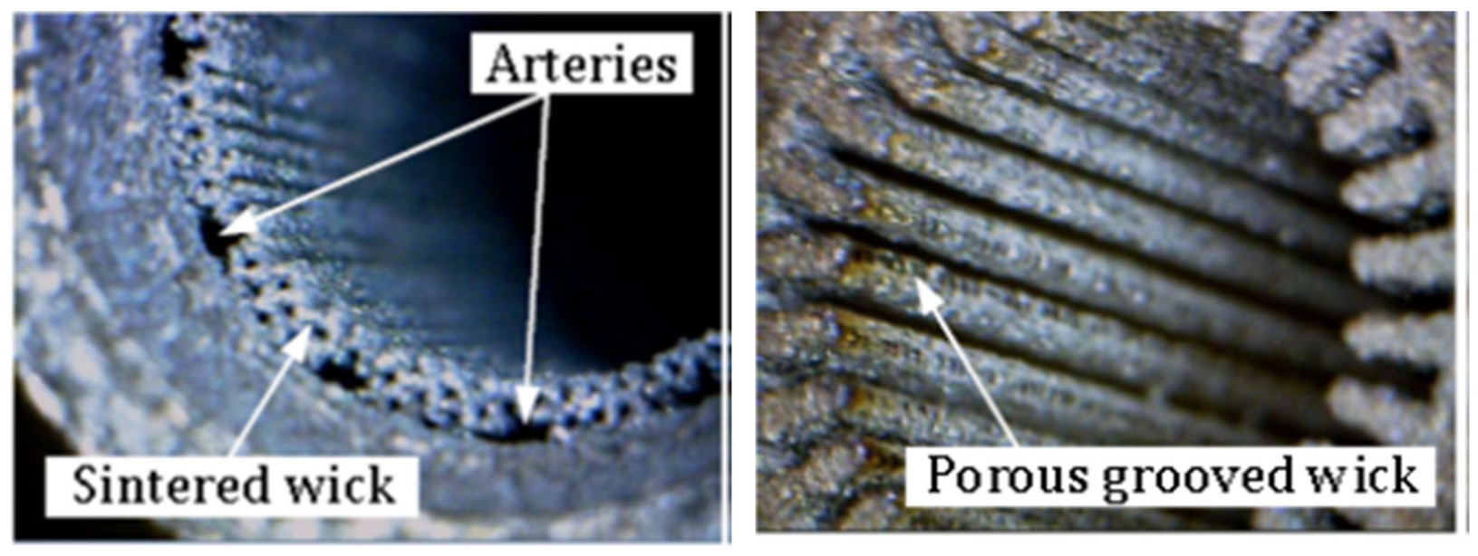
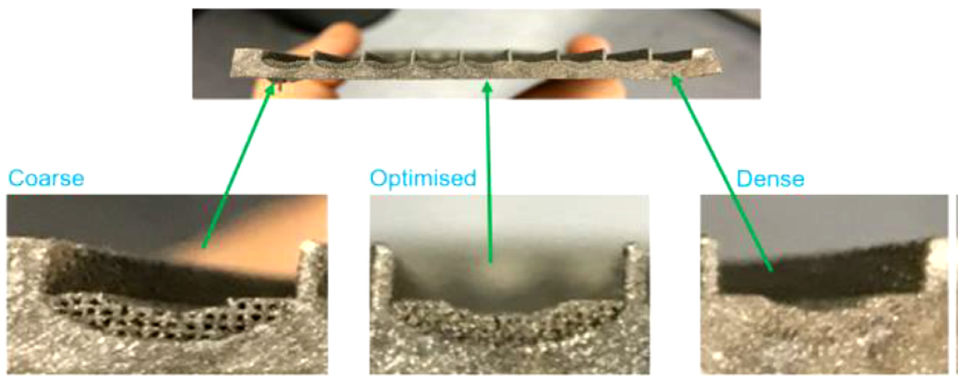
- Difficulties in manufacturing complicated, customised and efficient homogeneous porous structures with the desired porosity, permeability and pore radius. It can be particularly important in the production of bi-porous wick structures with enhanced thermal properties allowing HP to function against gravity. Such wicks are present in loop HP where the evaporator has wicks of different porosities and permeabilities (e.g., primary and secondary wick) and vapour passage network with different functions in loop HP evaporator [2,8,11,27];
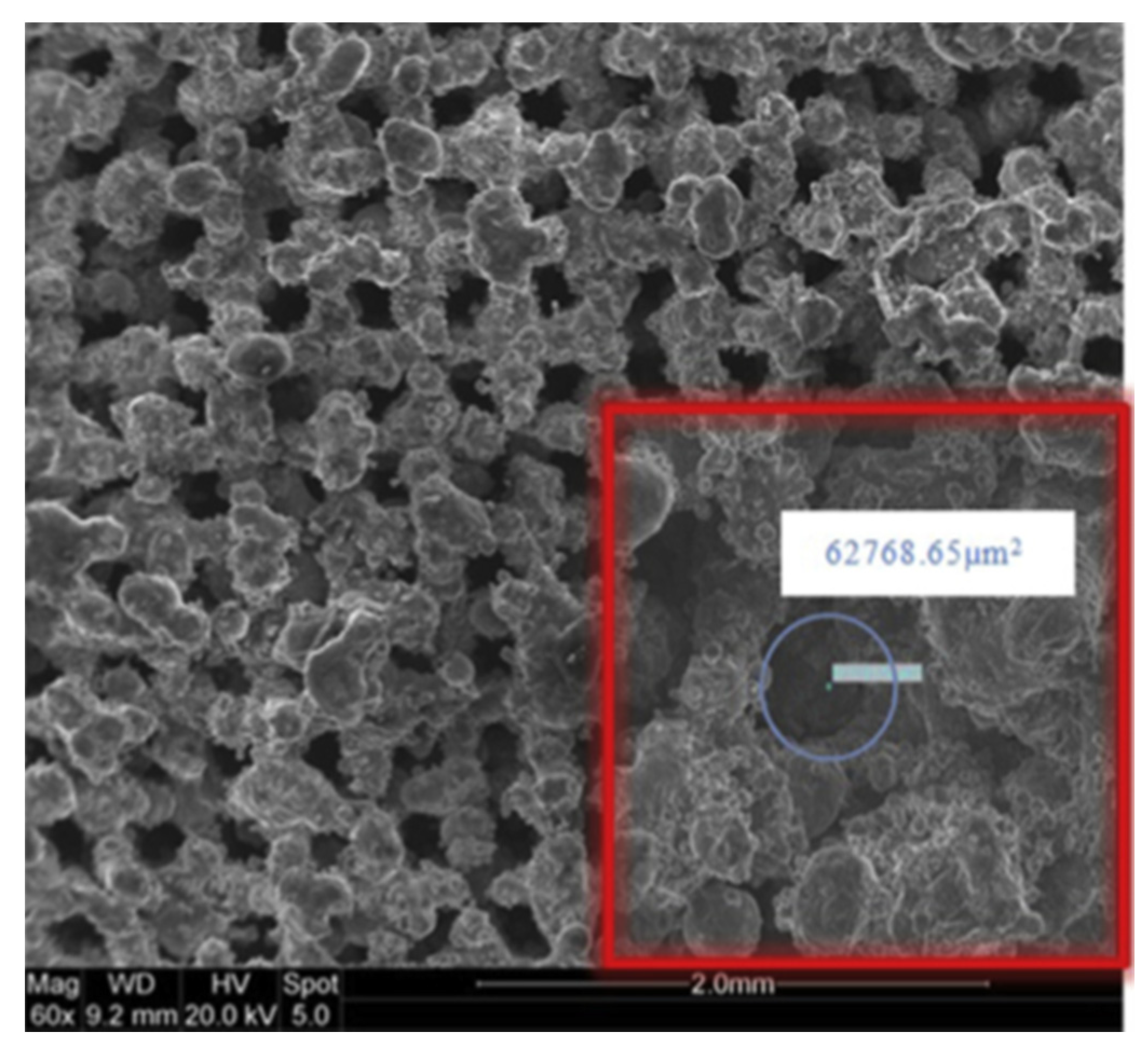
- Difficulties in production wicks with pores evenly distributed and not randomly located. Random internal porous structure [8];
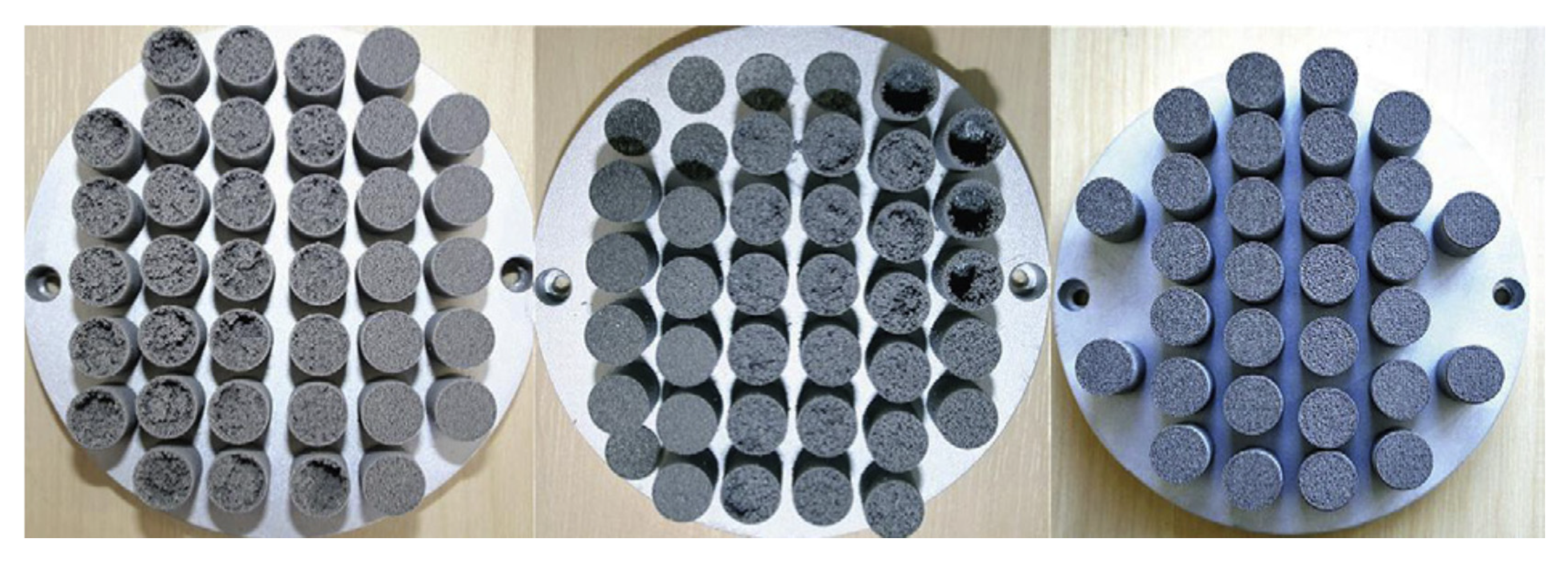
- Difficulties in manufacturing sintered wicks from specific and selected materials (e.g., aluminium). The random internal porous structure encourages heterogeneousness in the thermal behaviour of the wick [12].
2. Additive Manufacturing in HP
3. Conclusions
- Manufacturing unconventional, advanced and tailored HPs;
- Manufacturing complicated, customised and efficient homogenous wick structures with the desired thickness, porosity, uniform pore sizes, permeability where the pores are evenly distributed and not randomly located;
- Manufacturing gravity friendly wick structures and expanding functionality limits when operating at adverse elevation;
- Quicker lean time and cost reduction due to reduction in customisation and assembly costs;
- Possibility of integration of the HP into the electronic chassis that enable direct thermal management of heated elements and decrease its thermal resistance;
- Reduction in weight (and material use) of the part;
- Solve an engineering problem with sealing casing/wick structure in HPs by eliminating knife-edge seal;
- Manufacturing wicks from specific and selected materials (e.g., sintered aluminium);
- Prevent deformation and ballooning issues caused by elevated internal vapour pressure;
- Increase the total heat flux that can be dissipated by the HP;
- Improve the start-up performance of the HP, especially at the low heat loads;
Author Contributions
Funding
Institutional Review Board Statement
Informed Consent Statement
Data Availability Statement
Conflicts of Interest
References
- Reay, D.A.; Kew, P.A.; McGlen, R. Heat Pipes: Theory, Design and Applications, 6th ed.; Butterworth-Heinemann: Oxford, UK, 2013. [Google Scholar]
- McDonough, J.R. A perspective on the current and future roles of additive manufacturing in process engineering, with an emphasis on heat transfer. Therm. Sci. Eng. Prog. 2020, 19, 100594. [Google Scholar] [CrossRef]
- Zohuri, B. Heat Pipe Design and Technology Modern Applications for Practical Thermal Management; Springer International Publishing: Geneva, Switzerland, 2016. [Google Scholar]
- Wrobel, R.; McGlen, R. Opportunities and Challenges of Employing Heat-Pipes in Thermal Management of Electrical Machines. In Proceedings of the 2020 XXIV International Conference on Electrical Machines (ICEM 2020), Gothenburg, Sweden, 23–26 August 2020. [Google Scholar]
- Zhang, Y. Heat Pipes: Design, Applications and Technology; Nova Science Publishers Inc.: New York, NY, USA, 2018. [Google Scholar]
- Nazari, M.A.; Ahmadi, M.H.; Ghasempour, R.; Shafii, M.B.; Mahian, O.; Kalogirou, S.; Wongwises, S. A review on pulsating heat pipes: From solar to cryogenic applications. Appl. Energy 2018, 222, 475–484. [Google Scholar] [CrossRef]
- Kaur, I.; Singh, P. State-of-the-art in heat exchanger additive manufacturing. Int. J. Heat Mass Transf. 2021, 178, 121600. [Google Scholar] [CrossRef]
- Esarte, J.; Blanco, J.M.; Bernardini, A.; San-Jose, J.T. Optimizing the design of a two-phase cooling system loop heat pipe: Wick manufacturing with the 3D selective laser melting printing technique and prototype testing. Appl. Therm. Eng. 2017, 111, 407–419. [Google Scholar] [CrossRef]
- Blauciak, K.; Szymanski, P.; Mikielewicz, D. The Influence of Loop Heat Pipe Evaporator Porous Structure Parameters and Charge on Its Effectiveness for Ethanol and Water as Working Fluids. Materials 2021, 14, 7029. [Google Scholar] [CrossRef] [PubMed]
- Szymanski, P.; Law, R.; McGlen, R.J.; Reay, D.A. Recent Advances in Loop Heat Pipes with Flat Evaporator. Entropy 2021, 23, 1374. [Google Scholar] [CrossRef] [PubMed]
- Jafari, D.; Wits, W. The utilization of selective laser melting technology on heat transfer devices for thermal energy conversion applications: A review. Renew. Sustain. Energy Rev. 2018, 91, 420–442. [Google Scholar] [CrossRef]
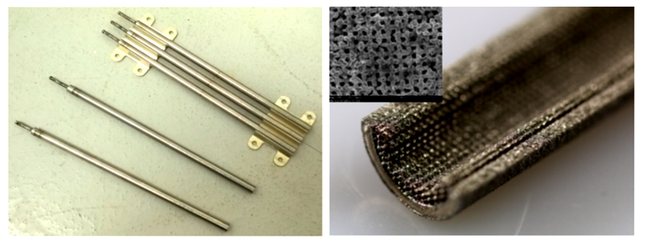
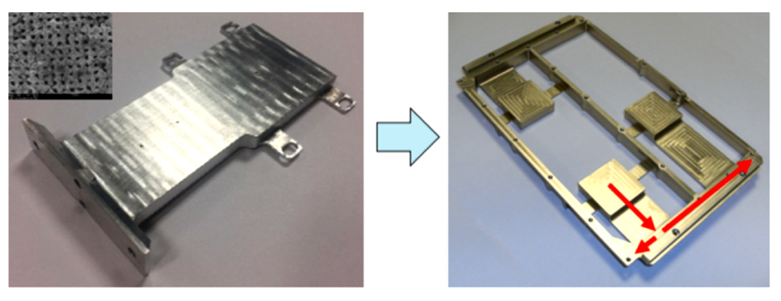
- Ameli, M.; Agnewa, B.; Leung, P.S.; Ng, B.; Sutcliffe, C.J.; Singh, J.; McGlen, R. A novel method for manufacturing sintered aluminium heat pipes (SAHP). Appl. Therm. Eng. 2013, 52, 498–504. [Google Scholar] [CrossRef]
- Jafari, D.; Wits, W.W.; Geurts, B.J. Metal 3D-printed wick structures for heat pipe application: Capillary performance analysis. Appl. Therm. Eng. 2018, 143, 403–414. [Google Scholar] [CrossRef]
- Jafari, D.; Wits, W.W.; Geurts, B.J. Phase change heat transfer characteristics of an additively manufactured wick for heat pipe applications. Appl. Therm. Eng. 2020, 168, 114890. [Google Scholar] [CrossRef]
- Jafari, D.; Alphen, K.J.H.; Geurts, B.J.; Wits, W.W.; Gonzalez, L.C.; Vaneker, T.H.J.; Rahman, N.U.; Romer, G.W.; Gibson, I. Porous materials additively manufactured at low energy: Single-layer manufacturing and characterization. Mater. Des. 2020, 191, 108654. [Google Scholar] [CrossRef]
- McGlen, R.J.; Sutcliffe, C.J. Additive Manufactured Titanium-Ammonia Heat Pipes for Thermal Management of Space Elec-tronic Devices. In Proceedings of the 50th International Conference on Environmental Systems, Lisbon, Portugal, 12–16 July 2020. [Google Scholar]
- McGlen, R. An introduction to additive manufactured heat pipe technology and advanced thermal management products. Therm. Sci. Eng. Prog. 2021, 25, 100941. [Google Scholar] [CrossRef]
- Furst, B.; Bugga, R.; Roberts, S. A Concept Demonstrator for an Additively Manufactured Li-ion Battery Case with Embedded Heat Pipes. In Proceedings of the 50th International Conference on Environmental Systems, Lisbon, Portugal, 12–16 July 2020. [Google Scholar]
- Jouhara, H.; Chauhan, A.; Nannou, T.; Almahmoud, S.; Delpech, B.; Wrobel, L.C. Heat pipe based systems—Advances and applications. Energy 2017, 128, 729–754. [Google Scholar] [CrossRef]
- Lanzo, D.T. Additively Manufactured Spacecraft Thermal Control System. Master’s Thesis, Department of The Air Force Air University, Air Force Institute of Technology, Wright-Patterson Air Force Base, OH, USA, 2017. [Google Scholar]
- Richard, B.; Anderson, B.; Chen, C.-H.; Crawmer, J.; Augustine, M. Development of a 3D Printed Loop Heat Pipe. In Proceedings of the 49th International Conference on Environmental Systems, ICES-2019-190, Boston, MA, USA, 7–11 July 2019. [Google Scholar]
- Richard, B.; Pellicone, D.; Anderson, B. Loop Heat Pipe Wick Fabrication via Additive Manufacturing. In Proceedings of the 19th IHPC and 13th IHPS, Pisa, Italy, 10–14 June 2018. [Google Scholar]
- Richard, B.; Pellicone, D.; Anderson, B. Loop Heat Pipe Wick Fabrication via Additive Manufacturing. In Proceedings of the 47th International Conference on Environmental Systems, Charleston, SC, USA, 16–20 July 2017. [Google Scholar]
- Maydanik, Y.F.; Chernysheva, M.A.; Pastukhov, V.G. Review: Loop heat pipes with flat evaporators. Appl. Therm. Eng. 2014, 67, 294–307. [Google Scholar] [CrossRef]
- Maidanik, Y.F.; Vershinin, S.V.; Chernysheva, M.A. Development and Tests of Miniature Loop Heat Pipe with a Flat Evaporator. SAE Trans. 2000, 109, 652–656. [Google Scholar]
- Maydanik, Y.F. Review: Loop heat pipes. Appl. Therm. Eng. 2005, 25, 635–657. [Google Scholar] [CrossRef]
- Gibbons, M.J.; Marengo, M.; Persoons, T. A review of heat pipe technology for foldable electronic devices. Appl. Therm. Eng. 2021, 194, 117087. [Google Scholar] [CrossRef]
- Ravi, B.R. Design, Fabrication, and Experimental Investigation of an Additively Manufactured Flat Plate Heat Pipe. Master’s Thesis, Polytechnic Institute and State University, Blacksburg, VA, USA, 2020. [Google Scholar]
- Werkheiser, N. 3D Printing in Space: The Next Frontier; NASA Marshall Space Flight Center: Huntsville, AL, USA, 2014. [Google Scholar]
- Horvath, J. 3D Printing with Matter Control, 1st ed.; Apress: New York, NY, USA, 2015. [Google Scholar]
- Guillen, D.P.; Wagner, A.; Moo, P. Additive Manufacturing of Heat Pipes. In Proceedings of the Idaho National Laboratory Clayton Turner University of Idaho TMS Annual Meeting, San Diego, CA, USA, 23–27 February 2020. [Google Scholar]
- Faveroa, G.; Bonessoa, M.; Rebesana, P.; Dimaa, R.; Pepatoa, A.; Mancina, S. Additive manufacturing for thermal management applications: From experimental results to numerical modelling. Int. J. Thermofluids 2021, 10, 100091. [Google Scholar] [CrossRef]
- Blakey-Milner, B.; Gradl, P.; Snedden, G.; Brooks, M.; Pitot, J.; Lopez, E.; Leary, M.; Berto, F.; Plessis, A. Metal additive manufacturing in aerospace: A review. Mater. Des. 2021, 209, 110008. [Google Scholar] [CrossRef]
- Mohseni-Gharyehsafa, B.; Lyulin, Y.V.; Evlashin, S.A.; Kabov, O.A.; Ouerdane, H. Characterization and performance of a 3D-printed two-phase closed thermosyphon. Therm. Sci. Eng. Prog. 2021, 28, 101001. [Google Scholar] [CrossRef]
- Chang, C.; Han, Z.; He, X.; Wang, Z.; Ji, Y. 3D printed aluminum flat heat pipes with micro grooves for efficient thermal management of high power LEDs. Nat. Sci. Rep. 2021, 11, 1–8. [Google Scholar] [CrossRef]
- Gupta, R.; Chen, C.H.; Anderson, W.G. Progress on 3D Printed Loop Heat Pipes. In Proceedings of the 50th International Conference on Environmental Systems ICES-2021-154, Virtual, 12–15 July 2021. [Google Scholar]
- Bernagozzi, M.; Georgoulas, A.; Miché, N.; Rouaud, C.; Marengo, M. Novel battery thermal management system for electric vehicles with a loop heat pipe and graphite sheet inserts. Appl. Therm. Eng. 2021, 194, 117061. [Google Scholar] [CrossRef]
- Bai, L.; Zhang, L.; Lin, G.; He, J.; Wen, D. Development of cryogenic loop heat pipes: A review and comparative analysis. Appl. Therm. Eng. 2015, 89, 180–191. [Google Scholar] [CrossRef]
- Hu, Z.; Wang, D.; Xu, J.; Zhang, L. Development of a loop heat pipe with the 3D printed stainless steel wick in the application of thermal management. Int. J. Heat Mass Transf. 2020, 161, 120258. [Google Scholar] [CrossRef]
- Furst, B.I.; Cappucci, S.; Roberts, S.N.; Daimaru, T.; Sunada, E.T.; O’Donnell, T.P. An Additively Manufactured Evaporator with Integrated Porous Structures for Two-Phase Thermal Control. In Proceedings of the 48th International Conference on Environmental Systems, Albuquerque, Mexico, 8–12 July 2018. [Google Scholar]
- Wrobel, R.; McGlen, R.J. Heat pipes in thermal management of electrical machines—A review. Therm. Sci. Eng. Prog. 2021, 26, 101053. [Google Scholar] [CrossRef]
- Ghahfarokhi, P.S.; Podgornovs, A.; Kallaste, A.; Cardoso, A.J.M.; Belahcen, A.; Vaimann, T.; Tiismus, H.; Asad, B. Opportunities and Challenges of Utilizing Additive Manufacturing Approaches in Thermal Management of Electrical Machines. IEEE Access 2021, 9, 36368–36381. [Google Scholar] [CrossRef]
- Ozguc, S.; Pai, S.; Pan, L.; Geoghegan, P.J.; Weibel, J.A. Experimental Demonstration of an Additively Manufactured Vapor Chamber Heat Spreader. In Proceedings of the 18th IEEE Intersociety Conference on Thermal and Thermomechanical Phenomena in Electronic Systems (ITherm), Las Vegas, NV, USA, 28–31 May 2019; pp. 416–422. [Google Scholar]
- Ibrahim, O.T.; Monroe, J.G.; Thompson, S.M.; Shamsaei, N.; Bilheux, H.; Elwany, A.; Bian, B. An investigation of a multilayered oscillating heat pipe additively manufactured from Ti-6Al-4V powder. Int. J. Heat Mass Transf. 2017, 108, 1036–1047. [Google Scholar] [CrossRef] [Green Version]
- Thompson, S.M.; Aspina, Z.S.; Shamsaei, N.; Elwany, A.; Bian, L. Additive manufacturing of heat exchangers: A case study on a multi-layered Ti–6Al–4V oscillating heat pipe. Addit. Manuf. 2015, 8, 163–174. [Google Scholar]
- Arai, T.; Kawaji, M. Thermal performance and flow characteristics in additive manufactured polycarbonate pulsating heat pipes with Novec 7000. Appl. Therm. Eng. 2021, 197, 117273. [Google Scholar] [CrossRef]
- Jafari, D.; Wits, W.W.; Vaneker, T.H.J.; Demir, A.G.; Previtali, B.; Geurts, B.J.; Gibson, I. Pulsed mode selective laser melting of porous structures: Structural and thermophysical characterization. Addit. Manuf. 2020, 35, 101263. [Google Scholar] [CrossRef]
- Shamvedi, D.; Mccarthy, O.J.; O’donoghue, E.; Danilenkoff, C.; O’leary, P.; Raghavendra, R. 3D metal printed heat sinks with longitudinally varying lattice structure sizes using direct metal laser sintering. Virtual Phys. Prototyp. 2018, 13, 301–310. [Google Scholar] [CrossRef]


| Research Group | Evaporator Casing Material | Dimensions | Power [W] | Thermal Resistance [°C/W] | Wick | Heat Transport Distance | The Main Benefit of Using AM Technology in Wick, HP, LHP and Oscillating HPs Manufacturing |
|---|---|---|---|---|---|---|---|
| Ameli et al., 2013 [12] | Aluminium | Ø14 mm × L70 mm | N/A | N/A * | Aluminium Pore radius 300 µm and 500 µm | 70 mm |
|
| Thompson et al., 2015 [46] | Titanium alloy Ti–6Al–4V | Flat plate 50.8 mm × 38.1 mm × 15.8 mm | 5–50 | 0.32 | Pore radius 15–45 µm | 50.8 mm |
|
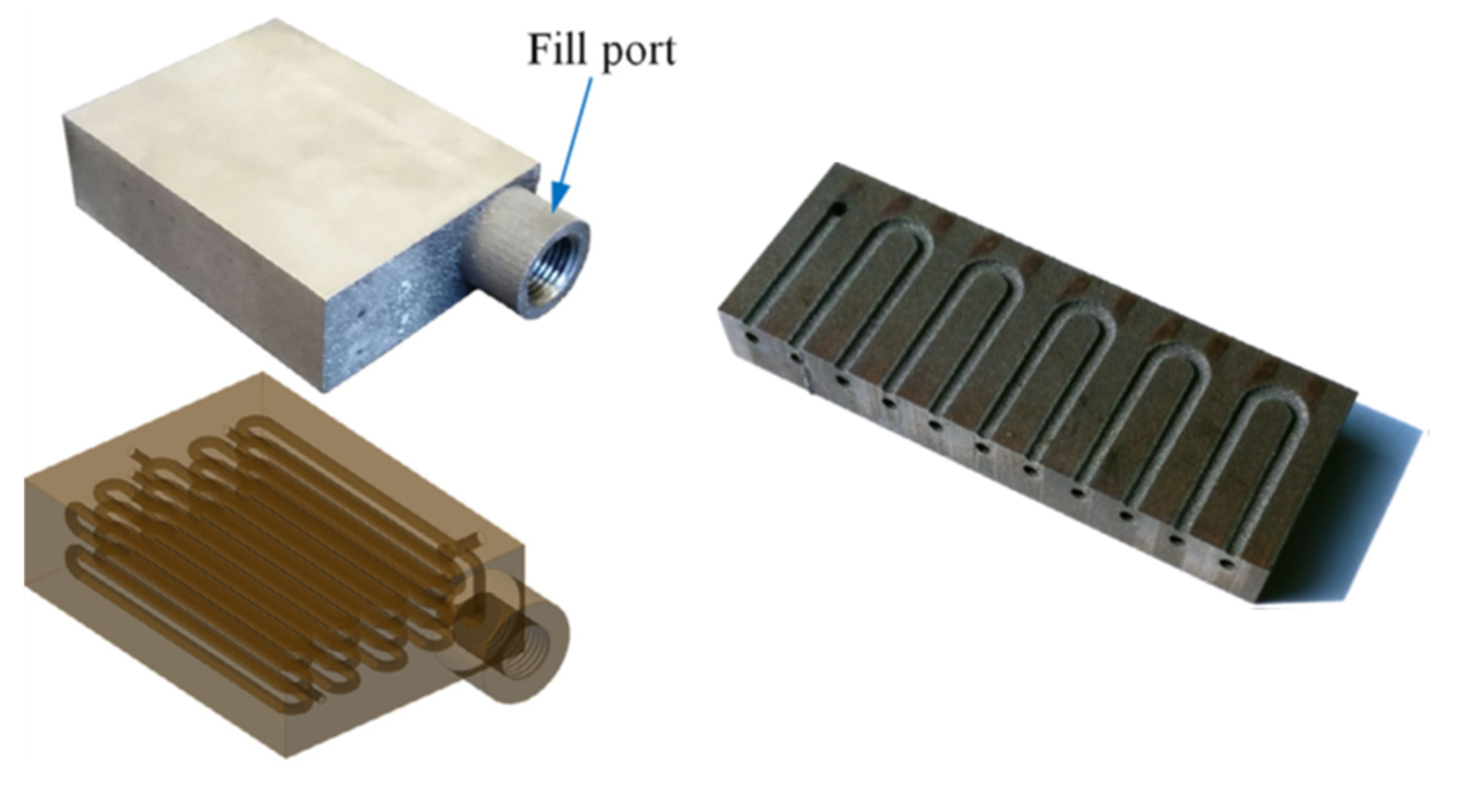
| Esarte et al., 2017 [8] | Copper | Volume 2827 mm3 Active length 23.2 mm | 57–120 | 0.15 | Stainless steel Pore radius 80 µm | 100 mm |
|
| Anderson et al., 2017–2021 [21,22,23] | Stainless steel | Ø25.4 mm × L10.16 mm | 5–350 | 0.13 | Stainless steel Pore radius 4.9 µm | N/A |
|
| Hu et al., 2020 [40] | Stainless steel | Flat dishØ 30 mm × H5 mm | 20–160 | 0.031 | Stainless steel Pore radius 100 µm | 150 mm |
|
| McGlen et. al., 2020 [17] | Titanium | Ø8 mm × L200 mm | 20–30 | N/A | Titanium Pore radius 100 µm | 200 mm |
|
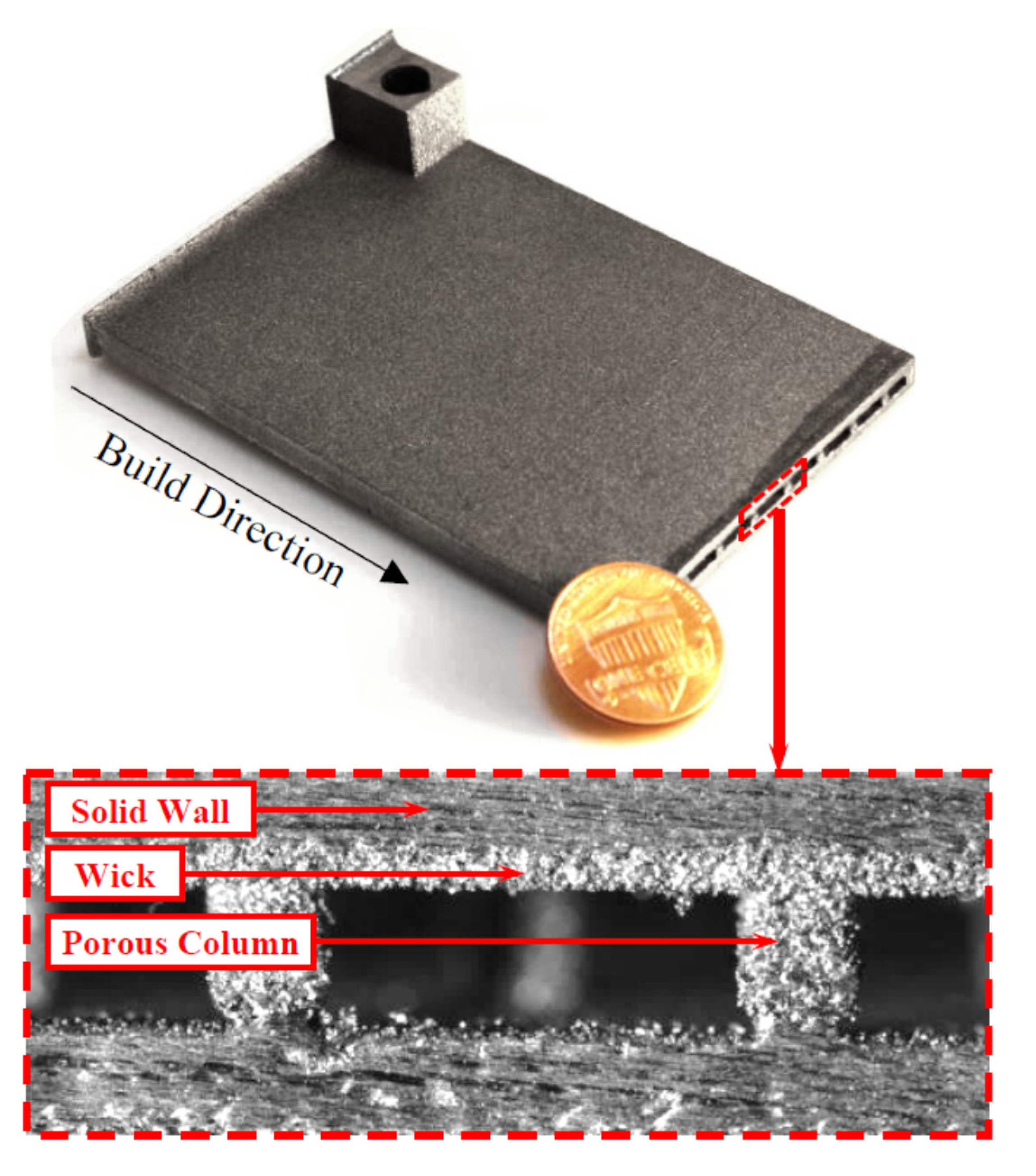
| Jafari et al., 2020 [13] | Stainless steel | Flat dish 40 mm × 20 mm × 6 mm | 0.15–16.5 | N/A | Stainless steel Pore radius 216 µm | 40 mm |
|
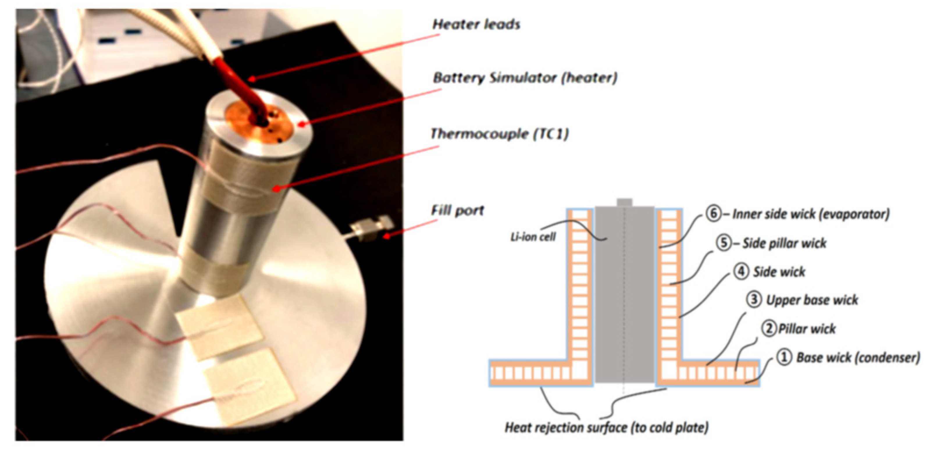
| Furst et al., 2020 [18] | Aluminium alloy AlSi10Mg | Cell Battery case | 60 | 0.037 | Pore radius 51 µm | 72.4 mm |
|
Publisher’s Note: MDPI stays neutral with regard to jurisdictional claims in published maps and institutional affiliations. |
© 2022 by the authors. Licensee MDPI, Basel, Switzerland. This article is an open access article distributed under the terms and conditions of the Creative Commons Attribution (CC BY) license (https://creativecommons.org/licenses/by/4.0/).
Share and Cite
Szymanski, P.; Mikielewicz, D. Additive Manufacturing as a Solution to Challenges Associated with Heat Pipe Production. Materials 2022, 15, 1609. https://doi.org/10.3390/ma15041609
Szymanski P, Mikielewicz D. Additive Manufacturing as a Solution to Challenges Associated with Heat Pipe Production. Materials. 2022; 15(4):1609. https://doi.org/10.3390/ma15041609
Chicago/Turabian StyleSzymanski, Pawel, and Dariusz Mikielewicz. 2022. "Additive Manufacturing as a Solution to Challenges Associated with Heat Pipe Production" Materials 15, no. 4: 1609. https://doi.org/10.3390/ma15041609