
Test on Compressive Performance of Concrete Filled Circular Steel Tube Connected by Thread through Inner Lining Tube
Abstract
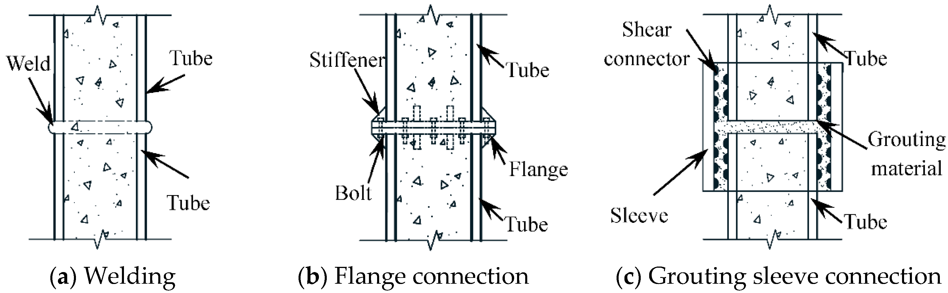
:1. Introduction
2. Test Survey
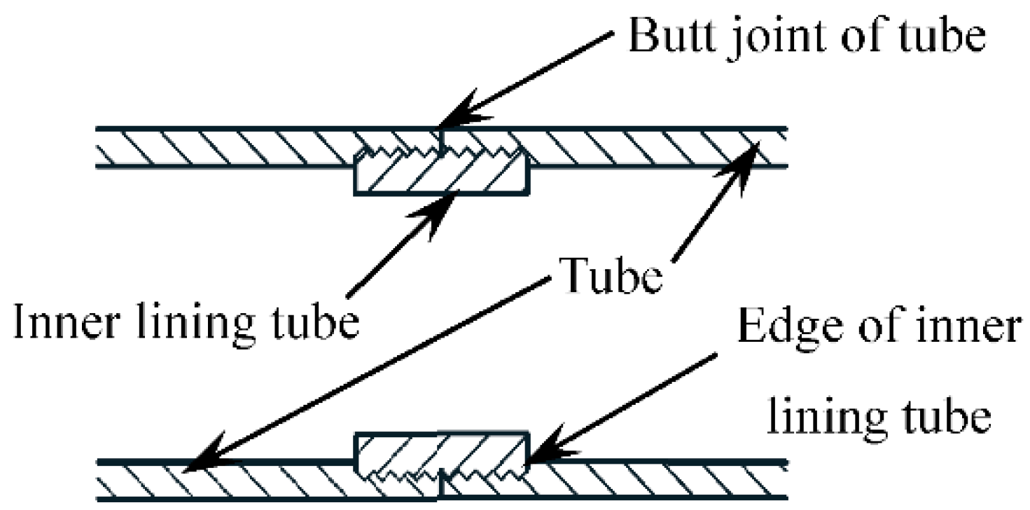
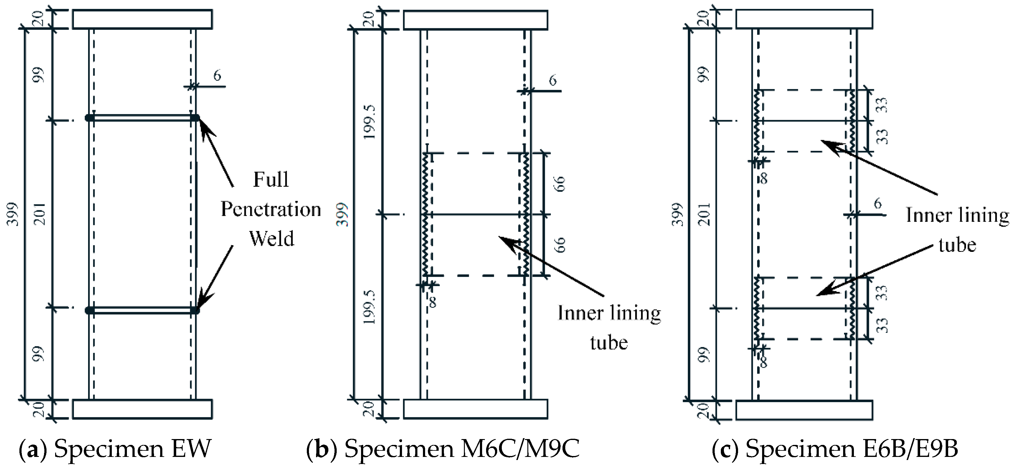
2.1. Specimen Design
2.2. Material Properties
2.2.1. Steel
2.2.2. Concrete
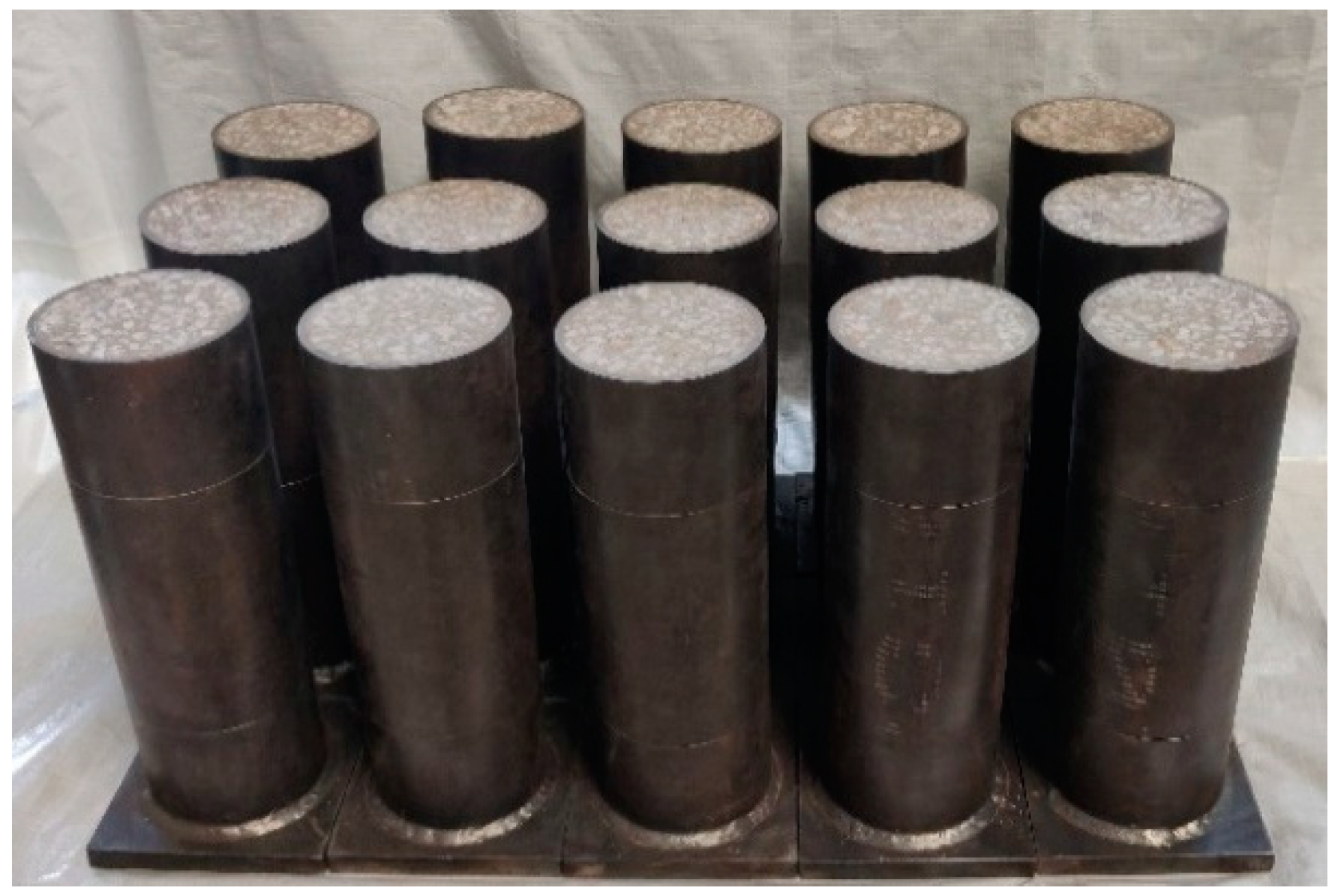
2.3. Specimen Fabrication
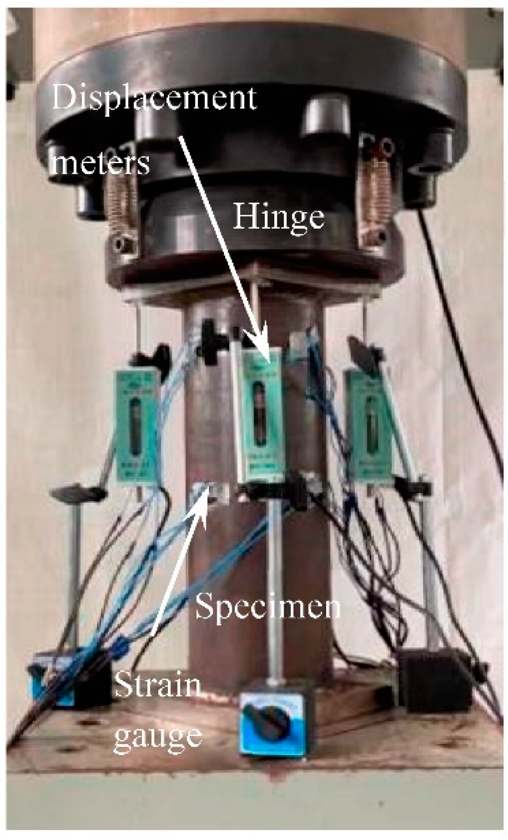
2.4. Loading and Measurement
3. Results and Discussion
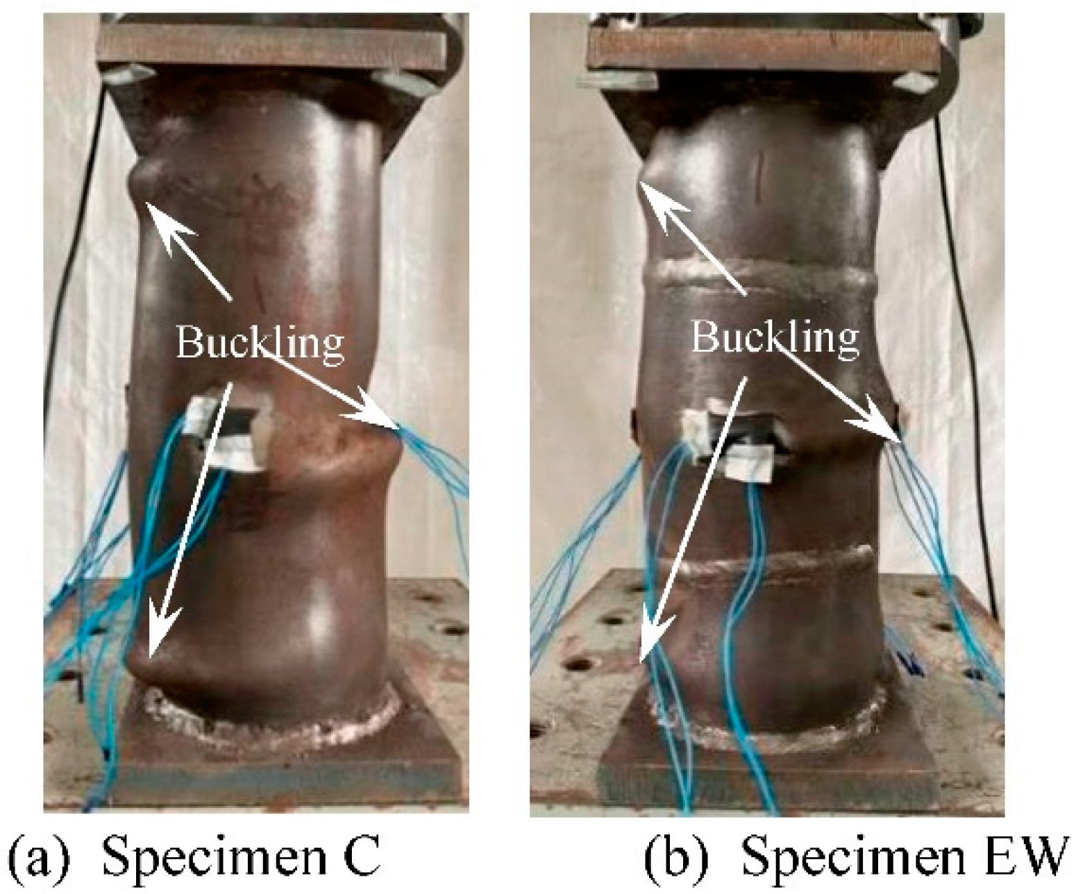
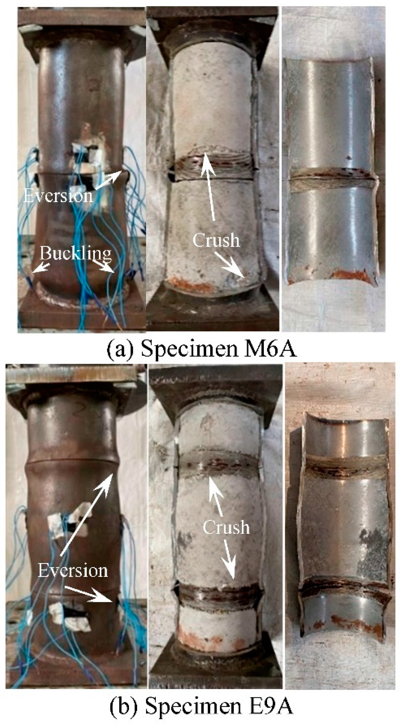
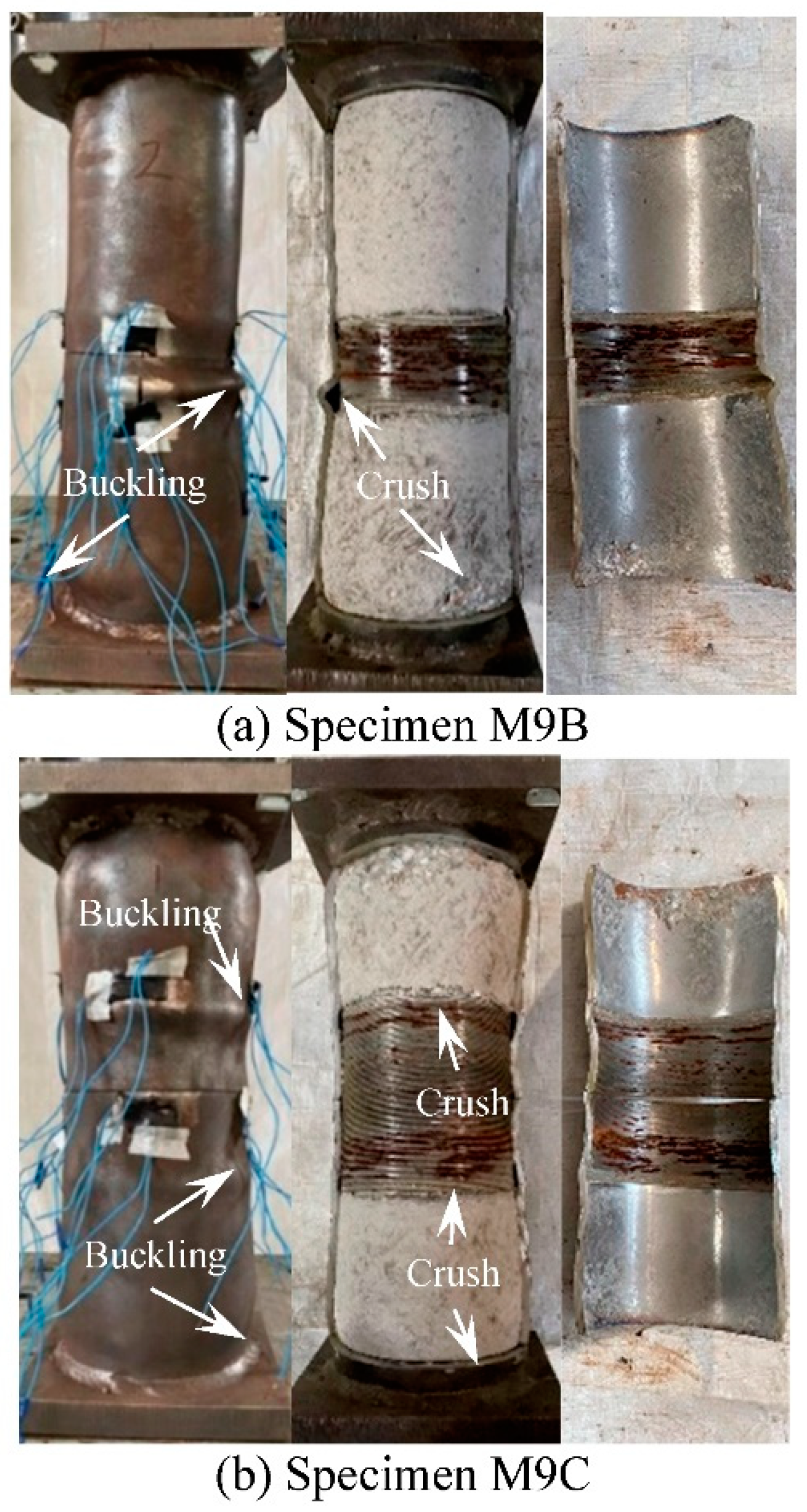
3.1. Specimen Failure Model
3.2. Test Curves
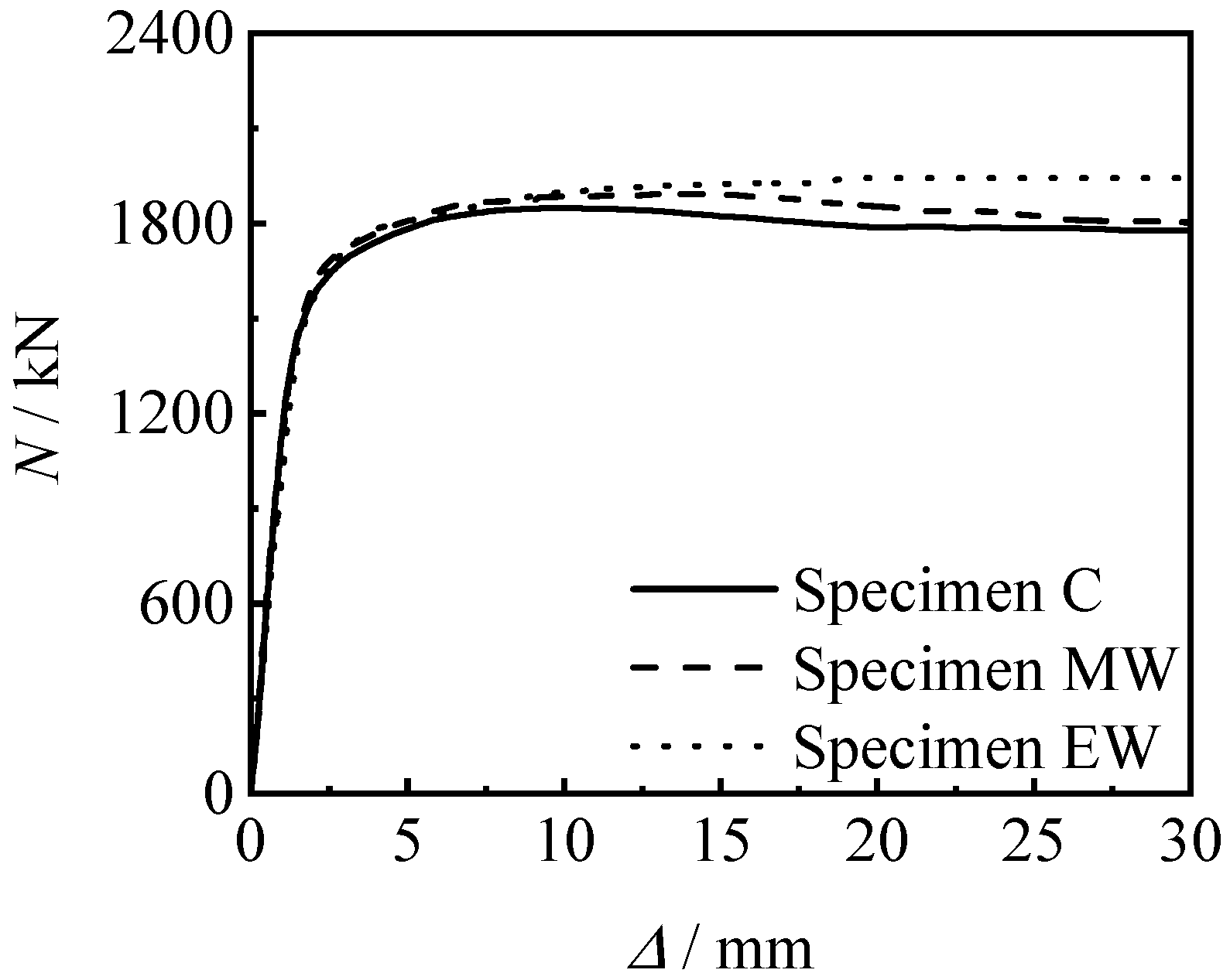
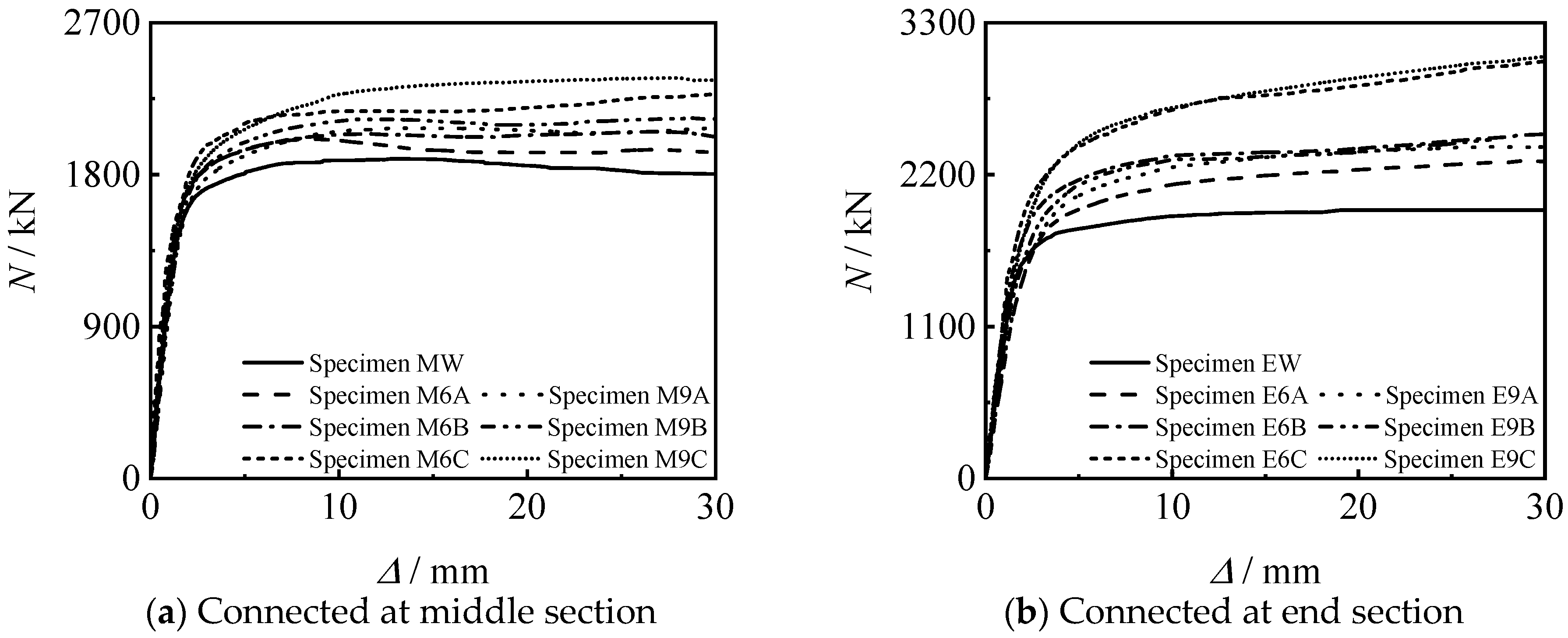
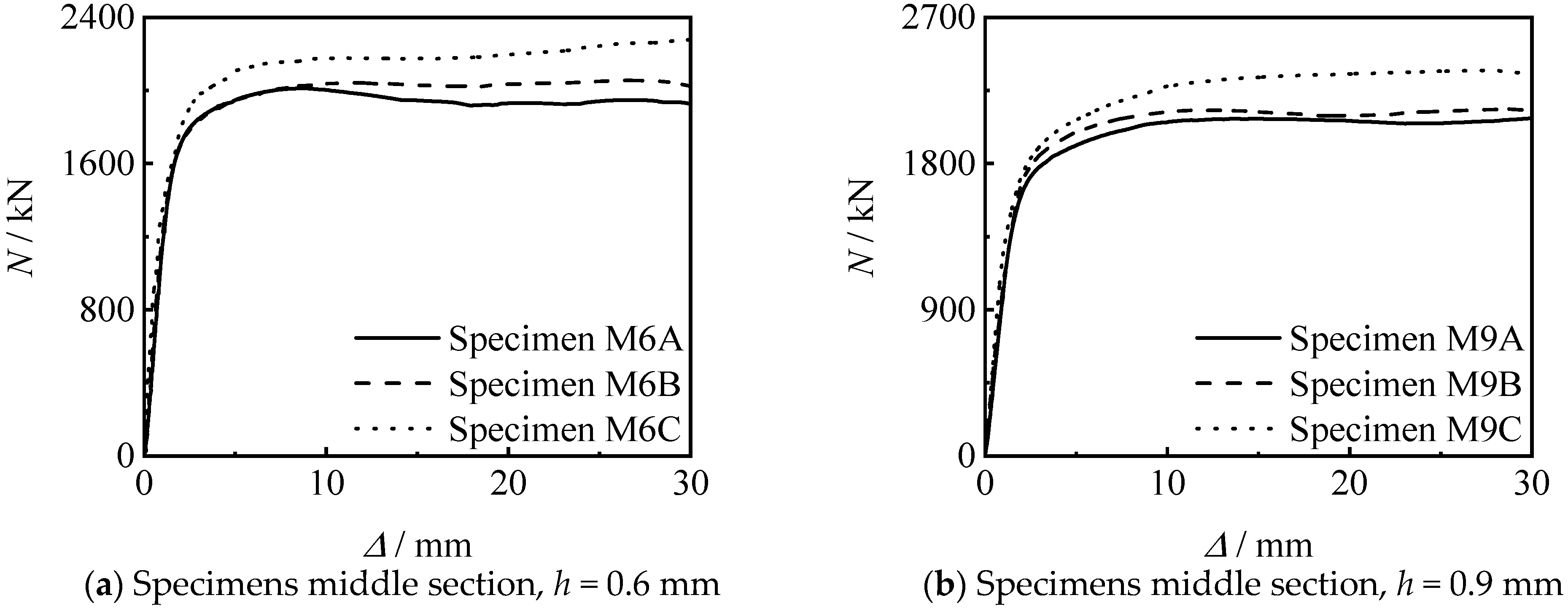
3.2.1. Axial Compressive Loading-Longitudinal Compressive Displacement Curves
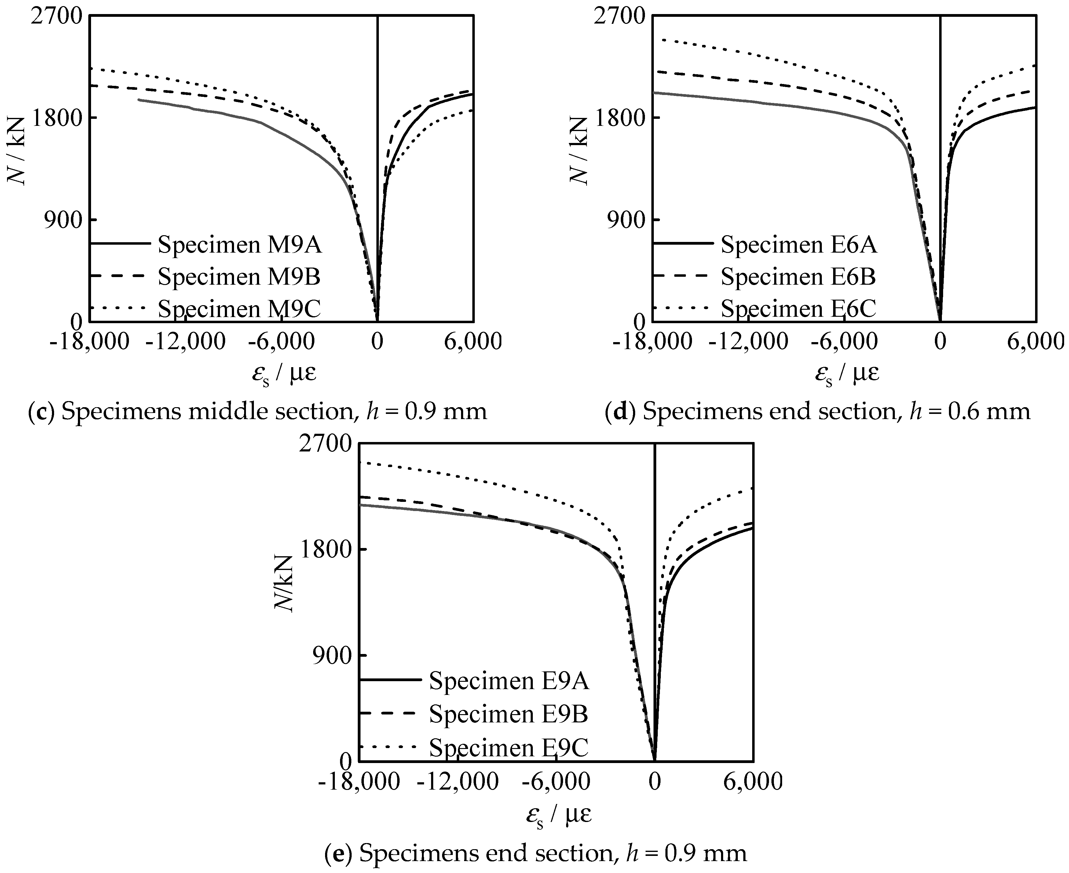
3.2.2. Analysis of Loading—Strain Curve
4. Analysis of Influencing Factors of Specimens Connected by Thread through Inner Lining Tube
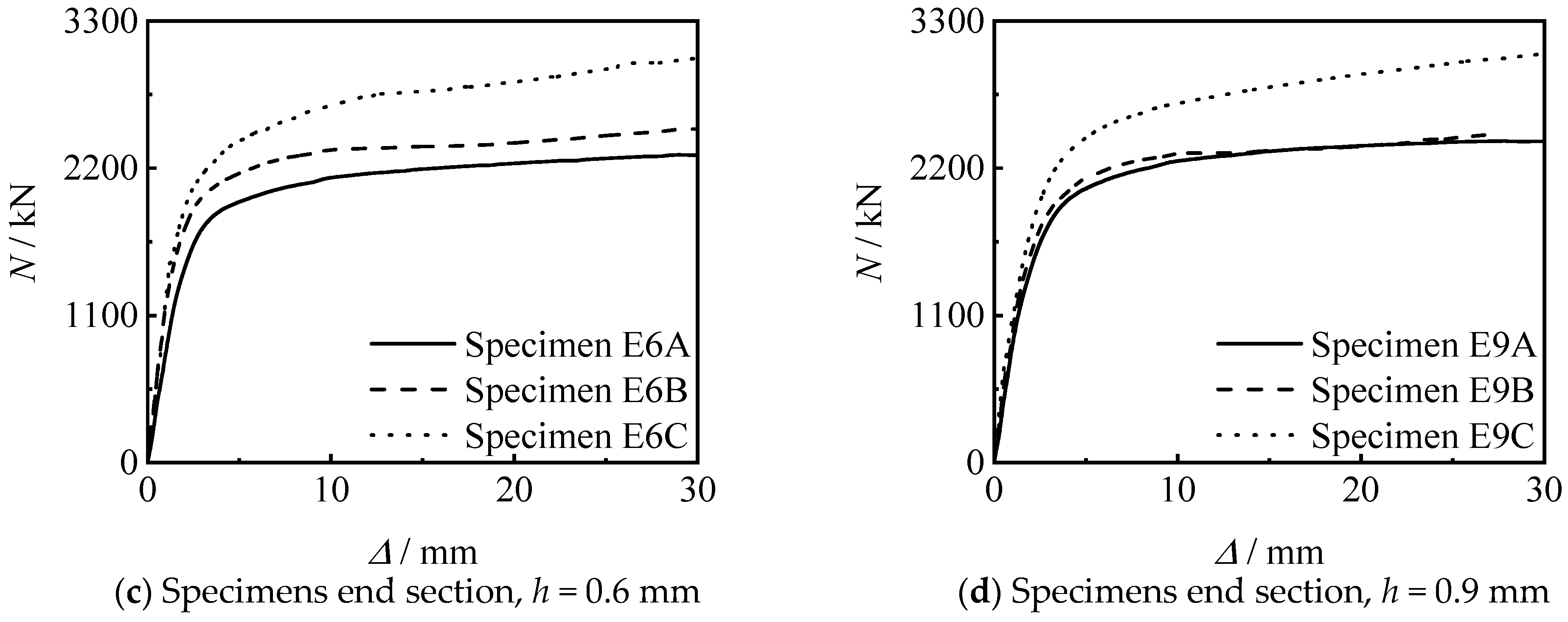
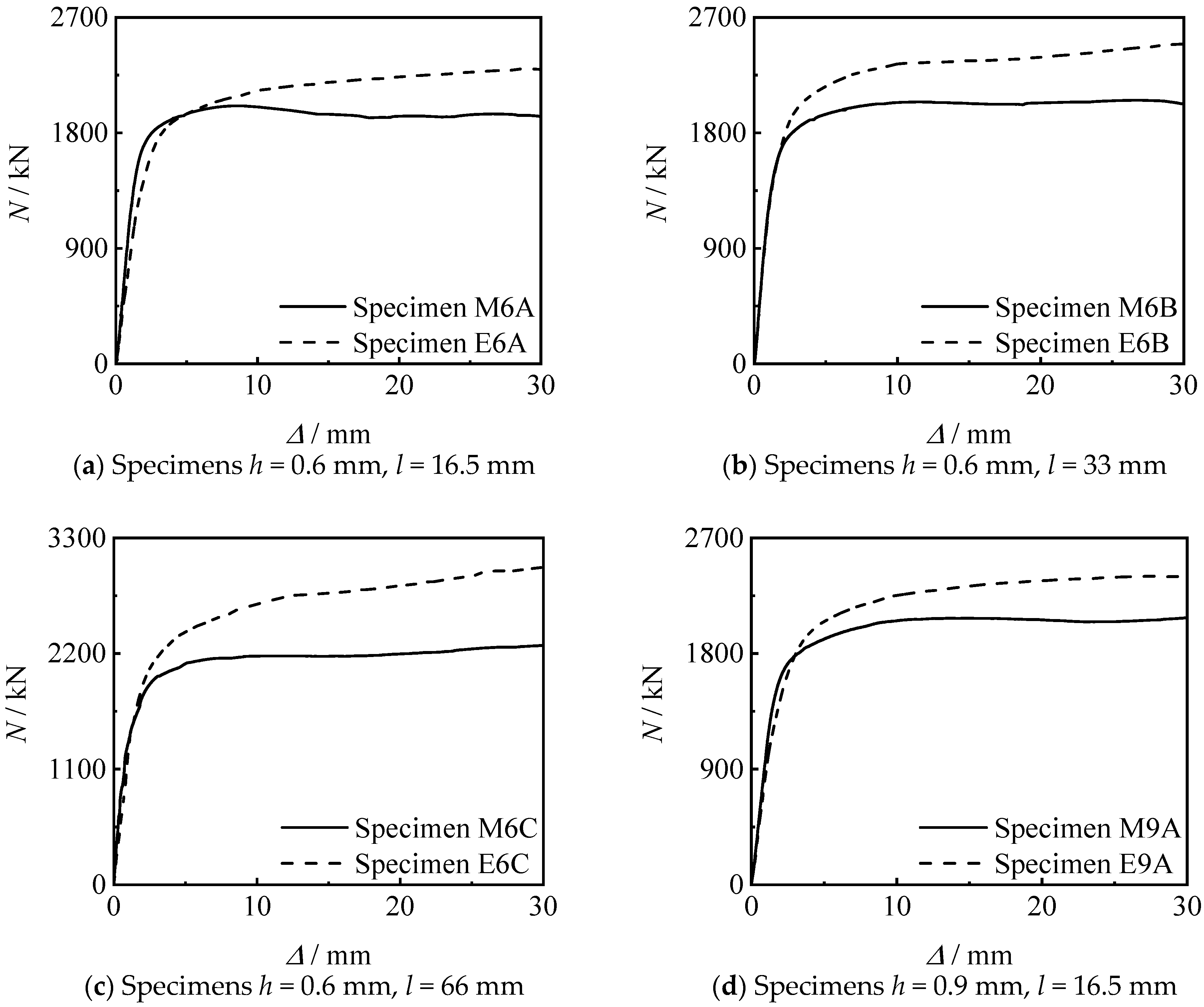
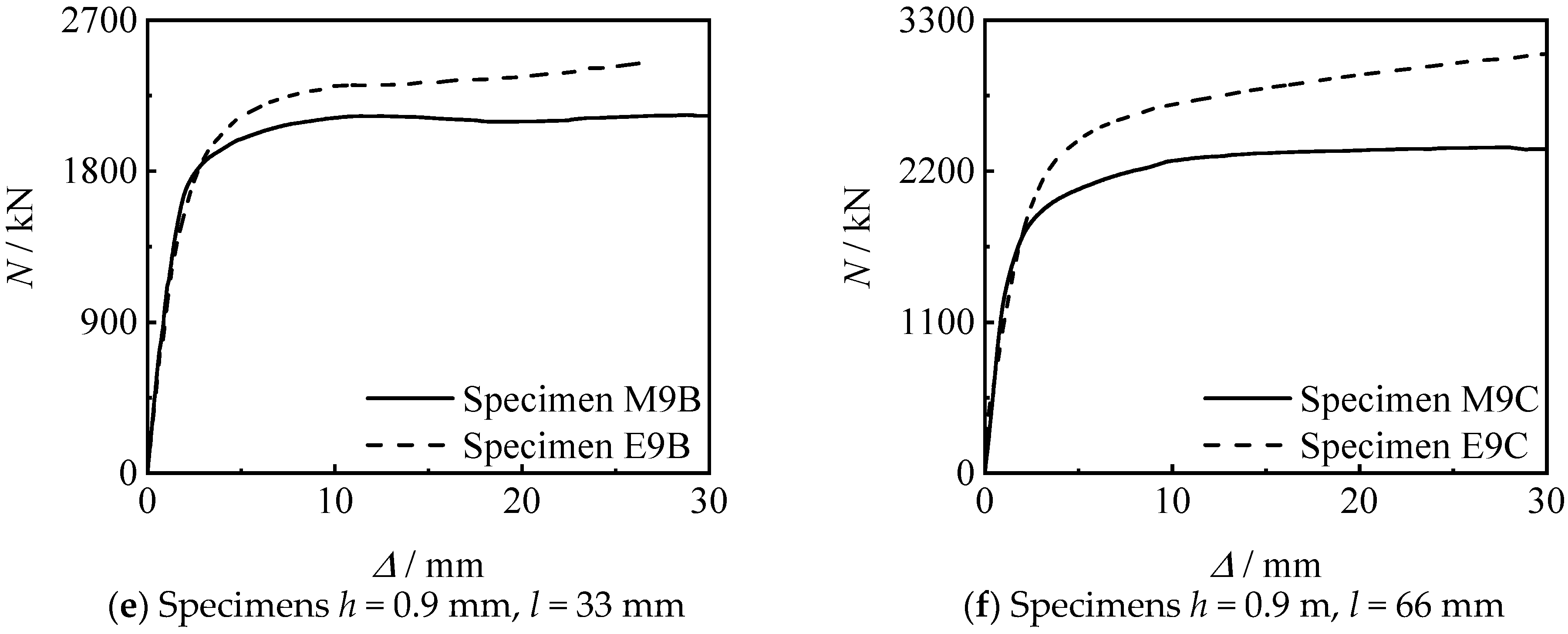
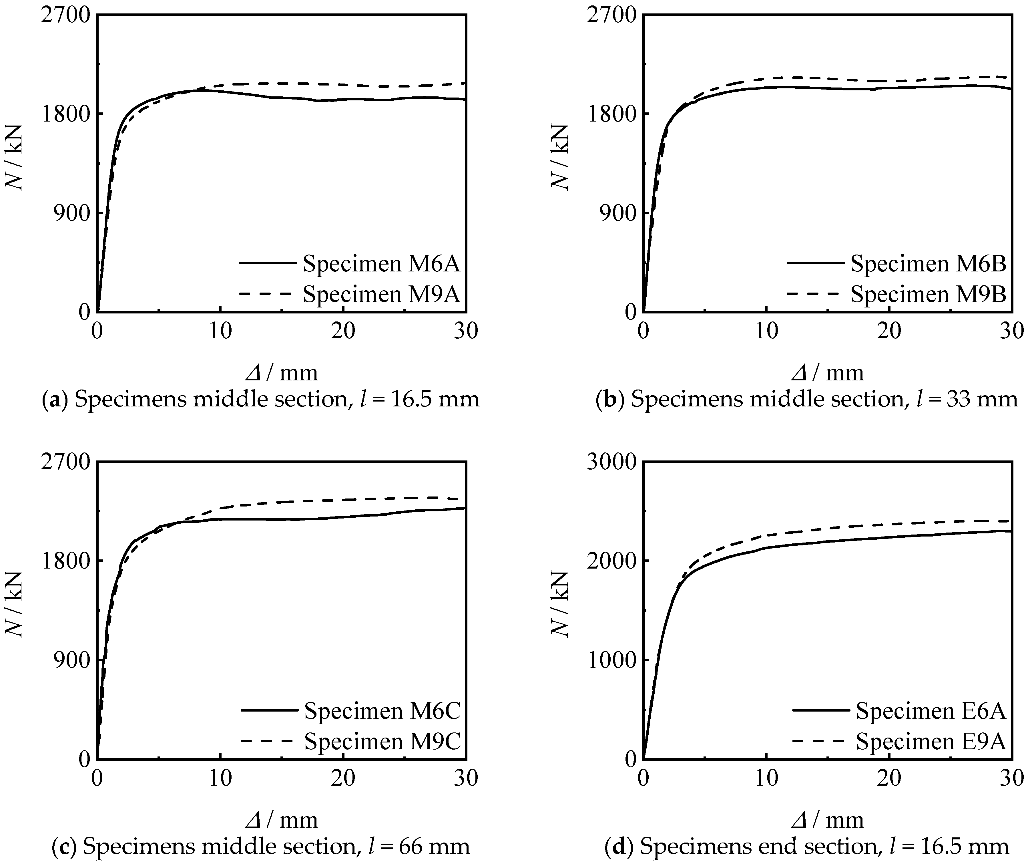
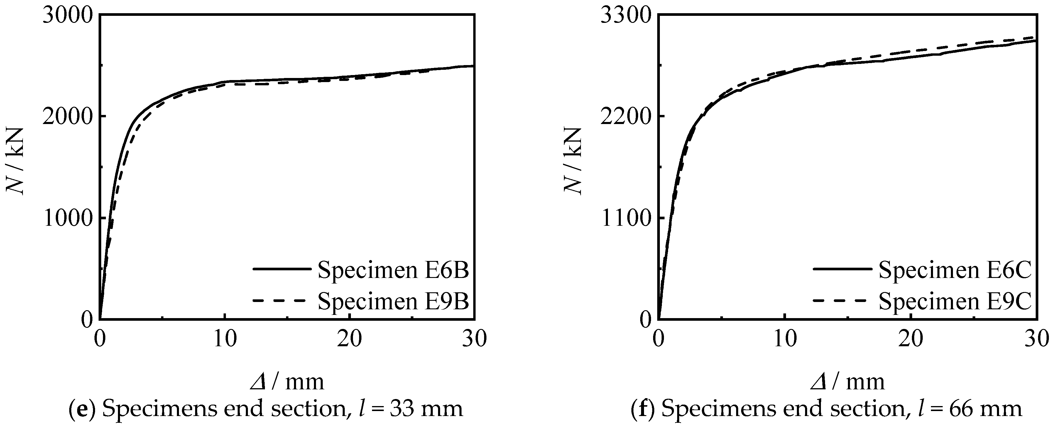
4.1. Thread Length
4.2. Thread Position
4.3. Thread Depth
5. Calculation of Load Bearing Capacity
6. Conclusions
Author Contributions
Funding
Institutional Review Board Statement
Informed Consent Statement
Data Availability Statement
Acknowledgments
Conflicts of Interest
References
- Han, L.H. Concrete-Filled Steel Tubular Structures—Theory and Practice, 3rd.; Science Press: Bejing, China, 2016. [Google Scholar]
- Ci, J.; Jia, H.; Chen, S.; Yan, W.; Song, T.; Kim, K.S. Performance analysis and bearing capacity calculation on circular concrete-filled double steel tubular stub columns under axial compression. Structures 2020, 25, 103–115. [Google Scholar] [CrossRef]
- Narayana, S.J.; Rao, K.M. A study on effect of steel tube in axial behavior of CFST stubs. In IOP Conference Series: Material Science and Engineering; IOP Publishing: Bristol, UK, 2020; Volume 1006. [Google Scholar]
- Zhu, J.Y.; Chen, J.B.; Chan, T.M. Analytical model for circular high strength concrete filled steel tubes under compression. Eng. Struct. 2021, 244, 1141–1152. [Google Scholar] [CrossRef]
- Thang, V.; Marshall, P. Studded bond enhancement for steel-concrete-steel sandwich shells. Ocean. Eng. 2015, 15, 31–39. [Google Scholar] [CrossRef]
- Ahmed, M.M.; El-Sayed Seleman, M.M.; Touileb, K.; Albaijan, I.; Habba, M.I. Microstructure, crystallographic texture, and mechanical properties of friction stir welded mild steel for shipbuilding applications. Materials 2022, 15, 2905. [Google Scholar] [CrossRef] [PubMed]
- Yan, L.; Wei, X.W.; Wang, H.; Wei, B. Mechanical behaviour of circular steel-reinforced concrete-filled steel tubular members under pure bending loads. Structures 2020, 112, 8–25. [Google Scholar]
- Bezerra, L.M.; Bonilla, J.; Silva, W.A.; Matias, W.T. Experimental and numerical studies of bolted T-stub steel connection with different flange thicknesses connected to a rigid base. Eng. Struct. 2020, 218, 110770. [Google Scholar] [CrossRef]
- Chen, Y.; Chen, C.; Xue, B. Experimental study of the bearing capacity of internal-external flange joints subjected to pressure and bending loadings with various eccentricities. Steel Constr. 2017, 32, 16–22. [Google Scholar]
- Guo, Y.; Wei, Y.; Yang, Z.; Huang, C.; Wu, X.; Yin, Q. Nonlinearity of interfaces and force transmission of bolted flange joints under impact loading. Int. J. Impact Eng. 2017, 109, 214–223. [Google Scholar] [CrossRef] [Green Version]
- Chen, J.; Yan, W.; Su, Y. Concrete filled steel tube grouting sleeve connection device design and its application. Appl. Mech. Mater. 2014, 18, 20–27. [Google Scholar]
- Wu, L.W.; Han, X.; Chen, H.B.; Li, Y.; Li, X. Study on flexural behavior of concrete filled circular steel tube members in different connections. J. Build. Struct. 2020, 41 (S1), 171–178. [Google Scholar]
- Wu, L.W.; Guo, X.X.; Chen, H.B. Calculation method for the axial load-bearing capacity of steel pipe-to-sleeve grouted connections. Constr. Build. Mater. 2022, 314, 125621. [Google Scholar] [CrossRef]
- Sun, W.B.; Yang, C.C.; Wei, F. Vehicular impacts on precast concrete bridge piers with grouted sleeve connections. Eng. Struct. 2022, 267, 114600. [Google Scholar] [CrossRef]
- Tan, W.; Min, Y.; Ze, G. Experimental investigation on the post-fire cyclic behavior of grouted sleeve connections. Constr. Build. Mater. 2021, 279, 122394. [Google Scholar]
- Zhao, Y.N.; Zhu, G.C. Technology of preparing honeycomb-like structure MgO from low grade magnesite. Int. J. Miner. Process. 2014, 126, 35–40. [Google Scholar]
- Yan, C.; Dian, L.Q.; Xu, L. Effect of La2O3 addition on the microstructural evolution and thermomechanical property of sintered low-grade magnesite. Ceram. Int. 2021, 47, 3136–3141. [Google Scholar]
- Pařenica, P.; Lehner, P.; Brožovský, J.; Krejsa, M. Numerical Models of the Connection of Thin-Walled Z-Profile Roof Purlins. Materials 2021, 14, 6573. [Google Scholar] [CrossRef] [PubMed]
- Flodr, J.; Krejsa, M.; Lehner, P. Temperature and Structural Analysis of Omega Clip. Int. J. Steel Struct. 2019, 19, 1295–1301. [Google Scholar] [CrossRef]
- GB/T 197-2018; General Purpose Screw Thread Tolerances. China Architecture Press: Beijing, China, 2018.
- GB/T 898-1988; Double End Stud bm=1d. China Standards Press: Beijing, China, 1988.
- GB 50661-2011; Code for Welding of Steel Structures. China Architecture & Building Press: Beijing, China, 2011.
- GB 50017-2017; Standard for Design of Steel Structures. China Architecture & Building Press: Beijing, China, 2017.
- American Concrete Institute. A Building Code Requirements for Structural Concrete and Commentary; American Concrete Institute: Farmington Hills, MI, USA, 2005. [Google Scholar]
- Thomas Telford. Design of Composite Steel and Concrete Structures—Part l-1: General Rules and Rules for Buildings; Thomas Telford: London, UK, 2004. [Google Scholar]
- Japan Architectural Society. Structural Design and Construction Index of Filling Steel Pipe; Japan Architectural Society: Tokyo, Japan, 1997. [Google Scholar]


| Serial Number | No. | Ds × ts × L/mm | Weld/Thread Position | h/mm | l/mm |
|---|---|---|---|---|---|
| 1 | C | 133 × 5.5 × 399 | – | – | – |
| 2 | MW | Middle section | – | – | |
| 3 | EW | End section | – | – | |
| 4 | M6A | Middle section | 0.6 | 16.5 | |
| 5 | M6B | Middle section | 0.6 | 33 | |
| 6 | M6C | Middle section | 0.6 | 66 | |
| 7 | M9A | Middle section | 0.9 | 16.5 | |
| 8 | M9B | Middle section | 0.9 | 33 | |
| 9 | M9C | Middle section | 0.9 | 66 | |
| 10 | E6A | End section | 0.6 | 16.5 | |
| 11 | E6B | End section | 0.6 | 33 | |
| 12 | E6C | End section | 0.6 | 66 | |
| 13 | E9A | End section | 0.9 | 16.5 | |
| 14 | E9B | End section | 0.9 | 33 | |
| 15 | E9C | End section | 0.9 | 66 |
| Type | fy/MPa | fu/MPa | Es/GPa | vs | δ/% |
|---|---|---|---|---|---|
| Steel tube | 420 | 570 | 215 | 0.28 | 20.7 |
| inner lining tube | 419 | 569 | 210 | 0.27 | 25.9 |
| Cement | Water | Sand | Low-Grade Magnesite |
|---|---|---|---|
| 432 | 168 | 558 | 1242 |
| No. | Test Value Nue/kN | Reference [1] Nuc/Nue | Reference [24] Nuc/Nue | Reference [25] Nuc/Nue | Reference [26] Nuc/Nue |
|---|---|---|---|---|---|
| M6A | 1841 | 1.00 | 0.75 | 0.90 | 0.90 |
| M6B | 1764 | 1.05 | 0.78 | 0.94 | 0.94 |
| M6C | 1810 | 1.02 | 0.76 | 0.91 | 0.91 |
| M9A | 1539 | 1.20 | 0.90 | 1.07 | 1.07 |
| M9B | 1695 | 1.09 | 0.81 | 0.98 | 0.97 |
| M9C | 1729 | 1.07 | 0.80 | 0.96 | 0.95 |
| E6A | 1782 | 1.03 | 0.77 | 0.93 | 0.93 |
| E6B | 1914 | 0.96 | 0.72 | 0.86 | 0.86 |
| E6C | 1849 | 1.00 | 0.75 | 0.89 | 0.89 |
| E9A | 1857 | 0.99 | 0.74 | 0.89 | 0.89 |
| E9B | 1868 | 0.99 | 0.74 | 0.88 | 0.88 |
| E9C | 2130 | 0.87 | 0.65 | 0.78 | 0.77 |
| Average value | 1.02 | 0.76 | 0.92 | 0.91 | |
| Mean square deviation | 0.079 | 0.059 | 0.071 | 0.071 | |
Publisher’s Note: MDPI stays neutral with regard to jurisdictional claims in published maps and institutional affiliations. |
© 2022 by the authors. Licensee MDPI, Basel, Switzerland. This article is an open access article distributed under the terms and conditions of the Creative Commons Attribution (CC BY) license (https://creativecommons.org/licenses/by/4.0/).
Share and Cite
Wang, Q.; Zhang, Y.; Peng, K. Test on Compressive Performance of Concrete Filled Circular Steel Tube Connected by Thread through Inner Lining Tube. Materials 2022, 15, 8619. https://doi.org/10.3390/ma15238619
Wang Q, Zhang Y, Peng K. Test on Compressive Performance of Concrete Filled Circular Steel Tube Connected by Thread through Inner Lining Tube. Materials. 2022; 15(23):8619. https://doi.org/10.3390/ma15238619
Chicago/Turabian StyleWang, Qingli, Yijing Zhang, and Kuan Peng. 2022. "Test on Compressive Performance of Concrete Filled Circular Steel Tube Connected by Thread through Inner Lining Tube" Materials 15, no. 23: 8619. https://doi.org/10.3390/ma15238619