Article

Imperfections Formation in Thin Layers of NiTi Triply Periodic Minimal Surface Lattices Fabricated Using Laser Powder Bed Fusion

1
Advanced Digital and Additive Manufacturing Center, Khalifa University of Science and Technology, Abu Dhabi P.O. Box 127788, United Arab Emirates
2
Department of Mechanical Engineering, Khalifa University of Science and Technology, Abu Dhabi P.O. Box 127788, United Arab Emirates
*
Author to whom correspondence should be addressed.
Materials 2022, 15(22), 7950; https://doi.org/10.3390/ma15227950
Submission received: 7 October 2022 / Revised: 24 October 2022 / Accepted: 27 October 2022 / Published: 10 November 2022
(This article belongs to the Special Issue 3D/4D Printing Application for Shape Memory Materials)

Abstract

:
In this paper, thin layers of NiTi shape memory alloy (SMA) triply periodic minimal surface lattices (TPMS) are fabricated using laser powder bed fusion (LPBF), considering different laser scanning strategies and relative densities. The obtained architected samples are studied using experimental methods to characterize their microstructural features, including the formation of cracks and balling imperfections. It is observed that balling is not only affected by the parameters of the fabrication process but also by structural characteristics, including the effective densities of the fabricated samples. In particular, it is reported here that higher densities of the TPMS geometries considered are generally associated with increased dimensions of balling imperfections. Moreover, scanning strategies at 45° angle with respect to the principal axes of the samples resulted in increased balling.

1. Introduction

NiTi shape memory alloys belong to the class of smart materials with a wide range of applications in the field of biomedical [1], aerospace [2], robotics [3], and automotive engineering [4]. Among other SMAs, NiTi remains the most widely used, owing to its high actuation energy density [5], superior functional properties, high ductility, low corrosion rate [6], biocompatibility [7], and high damping ratio [8]. Additive manufacturing (AM) has recently gained popularity in relation to the fabrication of NiTi intricate parts [9,10,11,12] because it naturally overcomes long-standing issues with conventional NiTi manufacturing techniques, including poor weldability [13] and machinability [14]. In comparison with other AM techniques, such as direct energy deposition [15], wire and arc additive manufacturing [16], laser powder bed fusion (LPBF) can provide better dimensional accuracy, generally denser parts, and the ability to fabricate more complex geometries with better surface finish [15]. Consequently, LPBF is one of the most utilized AM techniques for fabricating architected parts made of NiTi [17,18,19] as well as many other materials [20,21,22]. Architected porous NiTi constructs are attractive because they achieve low specific weight [23] combined with high specific stiffness and strength [24,25,26]. Moreover, porous/cellular structures may well be engineered for good fluid permeability [27,28], enhanced heat dissipation [29], and improved electrical properties [30]. They may further be used for artificial tissue engineering [31] and impact energy absorption [32]. Among porous structures, those featuring triply periodic minimal surface (TPMS) architectures have been gaining increased attention in parallel with the democratization of AM solutions [33,34,35]. These periodic three-dimensional architectures feature zero mean curvature and allow the segregation of space into two or more intertwined but non-connecting sub-domains. Moreover, TPMS structures have a large surface-to-volume ratio and are free of self-intersections.
In the literature, very few references [36,37,38,39] have addressed the fabrication of NiTi TPMS structures. In these papers, the properties of the printed TPMS structures are found to be significantly affected by fabrication process parameters, such as laser power, scan speed, energy density, layer thickness, hatch spacing, and scan strategy. The influence of scan strategy on the outcome of LPBF fabrication has received relatively little attention compared to parameters, such as laser power, scanning speed, hatch spacing, and layer thickness, which influence the rate at which energy is supplied to the powder bed. In this respect, Amirjan et al. [40] reported that rotating the scan vector between successive layers was more advantageous to obtain uniform temperature distribution during AM. Such rotation was found to gradually alter the direction of heat flux in-between layers, resulting in a more uniform temperature distribution. Therefore, the scan strategy was proposed to have the potential for printing isotropic materials with better mechanical properties. In contrast, the island scanning strategy, fractal scanning strategy, and spiral/helix scanning strategy usually involve shorter scan vectors. It was observed [41,42,43] that shorter scan vector lengths may help reduce residual stress and, thereby, improve mechanical properties. Ali et al. [44] highlighted an improvement in superelasticity in tension in SMAs due to alternating x/y axes scanning strategies. It was further concluded that scanning strategies played a significant role in microstructural evolution during solidification and thereby affecting mechanical as well as functional properties in SMAs. Kruth et al. [45] found that the greatest residual stress was developed perpendicular to the scan direction. However, other studies [46,47] contradicted the former finding and observed that the greatest stress was generated parallel to the scan direction. Ramos et al. [48] confirmed the influence of scanning strategies on residual stresses and deformation of the component and observed lower residual stress generation due to shorter scan vector length. It was also observed that sequences of scan vectors proved more effective in reducing the deformation of printed parts. In parallel, a combination of lower hatch spacing, higher power, and scan speed or, alternatively, moderate power and lower scan speed, was found to increase the density of AM fabricated parts.
In the present study, the influence of relative sample density and laser scanning strategy on the microstructure of NiTi TPMS layers is investigated for the first time. The results help address a gap in current research in relation to the influence of process parameters and structural design features on the behavior of NiTi TPMS lattices.

2. Materials and Methods

2.1. NiTi Powder

Gas-atomized pre-alloyed NiTi powder (Figure 1) was procured from TLS Technik GmbH & Co., Bitterfeld-Wolfen, Germany, with varying average particle sizes between 15 and 46 μm. The spherical particles were argon atomized and were packed in air-tight containers to avoid oxidation.

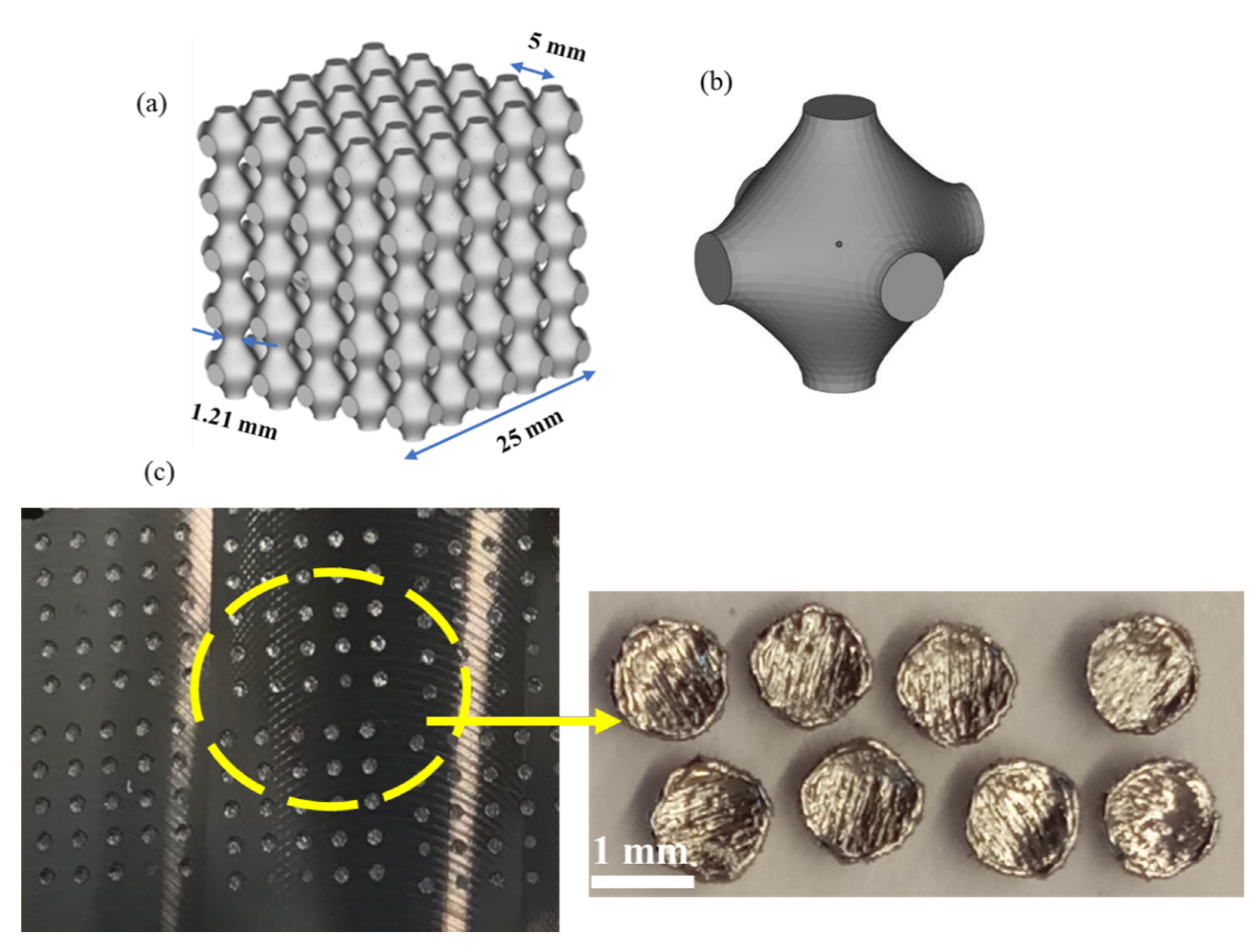
2.2. Design of TPMS Lattice Structures

In the present study, the Schwartz primitive TPMS topology was selected for the morphological investigation of additively printed structures. The geometries of the samples were generated considering approximate surface equations of the form shown in the Equation (1).
cos x + cos y + cos z = c
where x, y, z are Cartesian coordinates, and c is a level-set iso-value constant.
MSLattice [49] was employed to plot the TPMS structures, as shown in Figure 2. The samples consisted of cubic Schwartz primitive cells of length 25 mm and relative density in the range of 30% to 60%. The relative density ( ρ R ) is calculated based on the CAD model by dividing the volume filled by the sample by the volume of a cube with similar dimensions (reference cube), as follows (Equation (2)):
ρ R = V S V  
where V S is the volume of the solid part of the cell and V is its total volume.
The surface area per unit cell of the primitive lattice with 30% relative density was calculated to be 61.1 mm2. The surface area plays an important role in relation to the structural heat balance during AM. It affects the melt pool dynamics during solidification, thereby influencing the overall mechanical and functional properties of the fabricated samples. The strut thickness of primitive unit cell was 1.21 mm. The varying strut thickness and its geometry play a significant role during the solidification of the melt.
Figure 3 further illustrates the sectioning of the CAD model to obtain the studied primitive lattices.

2.3. Additive Manufacturing of the NiTi Samples

An EOS-M400 3D metal printer was used for additive manufacturing of the NiTi samples. The build chamber was preheated to 85 ° C and maintained at the same temperature during fabrication, and a Ti-alloy-based plate was utilized. Preheating to 85 °C was the highest preheating temperature that could be achieved for our experiment with the EOS M400-4. Reaching this temperature took almost 24 h, and it could not be increased further. One issue here is that the printer does not allow for preheating the inert gas flow, which results in convective heat loss in the build chamber. Higher preheating temperatures will likely be beneficial in moderating residual stress fields that may arise during the building process because of severe temperature gradients and metallurgical interactions. The printer has four Ytterbium-fiber lasers of 400 W maximum power each, a scanning speed of up to 7.0 m/s, and a build volume of 400 × 400 × 400 mm3. The focus diameter of the laser beam was around 90 μm with an arrangement of precision optics F-theta-lens. The atmosphere inside the build chamber was stringently maintained inert by the circulation of argon. The samples were fabricated using a layer thickness of 30 μm and a hatch spacing of 90 μm using a variety of scanning strategy, as shown in Figure 4.
The samples were fabricated using a constant scan speed of 425 mm/s and a laser power of 85 W. These parameters were chosen following an extensive review work [44]. Thin-layered samples of approximately 1.0 to 1.5 mm thickness in the build direction were fabricated against the proposed thickness of 25 mm. The printed samples were separated from the build plate by applying shear force at the base of prints using a scrapper and gentle tapping. However, issues with delamination and excessive warping (caused due to residual internal stresses owing to uneven cooling of printed samples) prevented the fabrication of thicker samples.

2.4. Metallographic Preparation

A Struers automatic grinder and polisher were used to grind and polish the primitive structures. The samples were hot-mounted before grinding at a pressure of 30 N and temperature of 180 °C in a Struers hot press using phenolic resin for 7 min. Silicon carbide grinding paper of successively decreasing grit sizes was used to fine grind the mounted samples. Using the slurry of suspended diamond abrasives of varying sizes (3–0.04 μm), the ground samples were finely polished. Colloidal silica suspension (0.02 μm) slurry was used at the final stage in order to obtain mirror-like surface polish. Sonication and plasma cleaning methods were used to remove the debris and contaminants on the surface of the polished samples. In order to obtain clear micrographs, contrast in the different microstructural features present in the samples was created using an etchant consisting of a diluted solution of hydrofluoric acid and nitric acid.

2.5. Microstructural Characterization

The microstructure of the powder and the printed samples was observed using a Schottky field emission SEM (JEOL JSM 7610F) at room temperature. Accelerating voltages of 3–10 keV were used for imaging. X-ray spectroscopy (EDX) of the powder and other samples was performed using an Oxford Instrument device at an accelerating voltage of 30 keV. The phase composition of the samples was determined using a Bruker Phase D2 diffractometer with Cu Kα radiation filter and an operating voltage of 30 kV. A step size of 0.5° was used for scanning with a 2θ variation from 5° to 90° at room temperature. The PDF-4 database was used to analyze the X-ray diffraction patterns.

3. Results and Discussion

AM of the NiTi primitive lattices was carried out using different sets of laser process parameters, as listed in Table 1.
Variation in relative density and scan strategy was investigated, maintaining fixed values for the process parameters.

3.1. Macroscopic Analysis

Figure 5 shows the scanning electron micrographs (SEM) of LPBF fabricated primitive TPMS structures with varying relative densities.
Preliminary macroscopic analysis shows the formation of spherical balls on the surface of the samples, as well as the presence of cracks. The laser tracks can also be clearly observed on the top surface of the samples, which have been marked in the figure for illustration. Several theories have been proposed in the literature [50,51,52] to explain the balling phenomenon commonly observed in samples fabricated using LPBF. In particular, the small size of the molten pool during laser melting is reported to cause solidification into spherical imperfections rather than forming a continuous surface. The presence of oxygen also promotes balling as it affects the wetting of the molten pool to the previous layer, thereby favoring ball formation rather than continuous lines over sublayers. Different shapes and sizes of balls have been reported, such as ellipsoidal balls and spherical balls [50]. The spattering of melt pool may also contribute to balling on the surfaces of the printed surfaces. In the present study, primarily spherical balls of varying sizes have been found, as shown in Figure 6.
With the increase in relative density, balling was found to increase. Sample RD60 shows the formation of balls of higher average sizes compared to the other samples, implying that higher relative densities may favor the formation of larger balls (greater than 50–60 μm). In contrast, the sample of 30% relative density showed the formation of small balls of average sizes less than 50–60 μm. In addition to balling, small cracks of various lengths and densities were observed in the samples. These are likely due to the rapid melting and solidification of the metal powder during LPBF, in which the cooling rate of the molten pool may reach up to 108 K/s. Such a high rate results in large temperature gradients in the solidified part, which, in turn, leads to potentially high residual stress [53,54]. The combination of high residual stress and large temperature gradient leads to the initiation and propagation of cracks in the fabricated parts. It was observed that samples with relative densities between 40% and 50% were less prone to cracking compared to those with 30% or 60% density. The correlation between density and propensity for cracking, therefore, appears to be a non-monotonic trend.
In terms of scan strategy, variations can be affected by controlling a range of process variables, including scan time, hatch spacing, scanning directions, scanning vector length, scanning vector rotation angle, and scanning sequence. In the present study, the scanning vector rotation angles of 0°, 45°, and 90° were selected to investigate their influence on the microstructure of the fabricated NiTi TPMS structures.
Figure 7 shows the electron micrographs of the primitive lattice samples fabricated using different scanning strategies. The macroscopic observation reveals the presence of balls and cracks on the external surfaces of the produced parts. As discussed earlier, balling imperfections are typically associated with the LPBF methods and can be found often. Laser process parameters optimization can be one of the methods to reduce or eliminate the balling. All samples, printed with different scan strategies, showed crack formation, as shown in Figure 8. However, scan strategies could influence the crack formation and their characteristics in LPBF-manufactured samples, as reported elsewhere [43,55]. As evident from Figure 7 and Figure 8, the inclined scan strategy has increased the balling in the fabricated parts as compared to other scan strategies. However, the average particle sizes remained between 40 and 60 μm.

3.2. Microscopic Analysis

Figure 9 shows the SEM images of LPBF manufactured NiTi TPMS lattice samples.
Figure 9a,b shows the fabricated samples with relative densities of 30% and 60%, respectively. Figure 9c,d shows the samples fabricated using different scan strategies, namely parallel strategies with 90° and 0° rotation, respectively. The microstructures show a wide range of grain shapes, sizes, and orientations.
In Figure 9b,d, cracks are seen to form along grain boundaries with crack lengths and opening significantly higher in Figure 9b. The formation of cracks, in Figure 9d in particular, is accompanied by strong grain size gradients. Such variation is indicative of non-uniform solidification during the fabrication processes. Changes in grain morphology, in addition to size, are also clearly visible in Figure 9c, with elongated grains near the bottom right transitioning toward more regular configurations into the bulk. Further transition from regular equiaxed grains to larger grains can be observed near the top left of the same micrograph. The inhomogeneity in the grain structures indicates a non-uniform cooling rate during solidification of the molten pool and has a strong influence on the mechanical properties of the fabricated samples. Improved homogeneity may be achievable through the optimization of the LPBF process parameters. The imperfections such as balling, cracks, and heterogenous microstructure can be deleterious to mechanical behaviors of the AM products and, therefore, need to be thoroughly investigated in order to inhibit their formations.

4. Conclusions

NiTi Schwarz primitive TPMS sample layers were manufactured using LPBF. The samples were fabricated considering varying relative densities and scanning strategies in order to study the microstructure of the built parts. Other laser process parameters, namely scan speed, hatch spacing, layer thickness, and laser power, were not varied during fabrication. The obtained samples were metallographically prepared, and their microstructural features were examined using SEM. Balling was observed in all the samples. However, it was most pronounced at the highest density of 60% without following a monotonic trend over the range of densities considered in this work. Moreover, balling was most noticeable in samples printed using an inclined scan strategy, and it was accompanied by a considerable formation of mostly intergranular cracks. No uniformly increasing or decreasing pattern was noted in the balling phenomenon vis-à-vis scan strategies. However, the parallel scanning strategy with interlayer rotation of 90° is considered more beneficial for obtaining even temperature distribution during AM, resulting in less residual stresses. Microstructure, on the other hand, indicated a non-uniform solidification rate, however, strict trends with relative density and scanning strategy could not be demonstrated. Balling on the surface of printed structures can also be due to the spattering of melt pool. The present work, therefore, suggests that the most commonly reported approach for optimizing LPBF parameters for fabricating nitinol, which relies on considering those parameters immediately influencing the laser energy density supplied to the powder, may need to be enriched with considerations of scan angle and overall structural topology and density when seeking LPBF fabricated parts of optimal quality.

Author Contributions

Conceptualization, W.Z. and S.H.; methodology, S.H. and A.N.A.; software, A.N.A. and S.H.; validation, S.H., A.N.A. and W.Z.; writing—original draft preparation, S.H.; writing—review and editing, S.H.; supervision, W.Z. All authors have read and agreed to the published version of the manuscript.

Funding

This work is supported by Khalifa University of Science and Technology grant No. CIRA 2021-099.

Institutional Review Board Statement

Not applicable.

Informed Consent Statement

Not applicable.

Data Availability Statement

Not applicable.

Acknowledgments

The authors wish to acknowledge the clean room facility (Micro Nano Fabrication Core Labs) at Masdar campus for facilitating the safe handling of hydrofluoric and nitric acid for chemical etching of NiTi samples.

Conflicts of Interest

Authors declare no conflict of interest.

References

  1. Duerig, T.; Pelton, A.; Stockel, D. An overview of nitinol medical applications. Mater. Sci. Eng. 1999, 275, 149–160. [Google Scholar] [CrossRef]
  2. Sofla, A.Y.N.; Meguid, S.A.; Tan, K.T.; Yeo, W.K. Shape Morphing of Aircraft Wing: Status and Challenges. Mater. Des. 2010, 31, 1284–1292. [Google Scholar] [CrossRef]
  3. Furuya, Y.; Shimada, H. Shape Memory Actuators for Robotic Applications. Mater. Des. 1991, 12, 21–28. [Google Scholar] [CrossRef]
  4. Stoeckel, D. Shape Memory Actuators for Automotive Applications. Mater. Des. 1990, 11, 302–307. [Google Scholar] [CrossRef]
  5. Lagoudas, D.C. Shape Memory Alloys: Modeling and Engineering Applications; Springer: Berlin/Heidelberg, Germany, 2008; ISBN 0387476857. [Google Scholar]
  6. Kuphasuk, C.; Oshida, Y.; Andres, C.J.; Hovijitra, S.T.; Barco, M.T.; Brown, D.T. Electrochemical Corrosion of Titanium and Titanium-Based Alloys. J. Prosthet. Dent. 2001, 85, 195–202. [Google Scholar] [CrossRef] [PubMed]
  7. Moghaddam, N.S.; Elahinia, M.; Miller, M.; Dean, D. Enhancement of Bone Implants by Substituting Nitinol for Titanium (Ti-6Al-4V): A Modeling Comparison. In Proceedings of the Smart Materials, Adaptive Structures and Intelligent Systems; American Society of Mechanical Engineers: Louisville, KY, USA, 2014; Volume 46148, p. V001T03A031. [Google Scholar]
  8. De Wild, M.; Meier, F.; Bormann, T.; Howald, C.B.C.; Müller, B. Damping of Selective-Laser-Melted NiTi for Medical Implants. J. Mater. Eng. Perform. 2014, 23, 2614–2619. [Google Scholar] [CrossRef] [Green Version]
  9. Wang, J.; Pan, Z.; Yang, G.; Han, J.; Chen, X.; Li, H. Location Dependence of Microstructure, Phase Transformation Temperature and Mechanical Properties on Ni-Rich NiTi Alloy Fabricated by Wire Arc Additive Manufacturing. Mater. Sci. Eng. A 2019, 749, 218–222. [Google Scholar] [CrossRef]
  10. Kumar, S.S.; Marandi, L.; Balla, V.K.; Bysakh, S.; Piorunek, D.; Eggeler, G.; Das, M.; Sen, I. Microstructure—Property Correlations for Additively Manufactured NiTi Based Shape Memory Alloys. Materialia 2019, 8, 100456. [Google Scholar] [CrossRef]
  11. Mitchell, A.; Lafont, U.; Hołyńska, M.; Semprimoschnig, C. Additive Manufacturing—A Review of 4D Printing and Future Applications. Addit. Manuf. 2018, 24, 606–626. [Google Scholar] [CrossRef]
  12. Mahmoudi, M.; Tapia, G.; Franco, B.; Ma, J.; Arroyave, R.; Karaman, I.; Elwany, A. On the Printability and Transformation Behavior of Nickel-Titanium Shape Memory Alloys Fabricated Using Laser Powder-Bed Fusion Additive Manufacturing. J. Manuf. Process. 2018, 35, 672–680. [Google Scholar] [CrossRef]
  13. Oliveira, J.P.; Miranda, R.M.; Braz Fernandes, F.M. Welding and Joining of NiTi Shape Memory Alloys: A Review. Prog. Mater. Sci. 2017, 88, 412–466. [Google Scholar] [CrossRef]
  14. Cunningham, C.R.; Flynn, J.M.; Shokrani, A.; Dhokia, V.; Newman, S.T. Invited Review Article: Strategies and Processes for High Quality Wire Arc Additive Manufacturing. Addit. Manuf. 2018, 22, 672–686. [Google Scholar] [CrossRef]
  15. DebRoy, T.; Wei, H.L.; Zuback, J.S.; Mukherjee, T.; Elmer, J.W.; Milewski, J.O.; Beese, A.M.; Wilson-Heid, A.; De, A.; Zhang, W. Additive Manufacturing of Metallic Components—Process, Structure and Properties. Prog. Mater. Sci. 2018, 92, 112–224. [Google Scholar] [CrossRef]
  16. Abe, T.; Sasahara, H. Layer Geometry Control for the Fabrication of Lattice Structures by Wire and Arc Additive Manufacturing. Addit. Manuf. 2019, 28, 639–648. [Google Scholar] [CrossRef]
  17. Dadbakhsh, S.; Vrancken, B.; Kruth, J.-P.; Luyten, J.; Van Humbeeck, J. Texture and Anisotropy in Selective Laser Melting of NiTi Alloy. Mater. Sci. Eng. A 2016, 650, 225–232. [Google Scholar] [CrossRef]
  18. Dadbakhsh, S.; Speirs, M.; Kruth, J.P.; Schrooten, J.; Luyten, J.; Van Humbeeck, J. Effect of SLM Parameters on Transformation Temperatures of Shape Memory Nickel Titanium Parts. Adv. Eng. Mater. 2014, 16, 1140–1146. [Google Scholar] [CrossRef]
  19. Li, S.; Hassanin, H.; Attallah, M.M.; Adkins, N.J.E.; Essa, K. The Development of TiNi-Based Negative Poisson’s Ratio Structure Using Selective Laser Melting. Acta Mater. 2016, 105, 75–83. [Google Scholar] [CrossRef] [Green Version]
  20. Ishizaki, K.; Komarneni, S.; Nanko, M. Porous Materials: Process Technology and Applications; Springer Science & Business Media: Berlin/Heidelberg, Germany, 2013; Volume 4, ISBN 1461558115. [Google Scholar]
  21. Kitagawa, S. Future Porous Materials. Acc. Chem. Res. 2017, 50, 514–516. [Google Scholar] [CrossRef]
  22. Barton, T.J.; Bull, L.M.; Klemperer, W.G.; Loy, D.A.; McEnaney, B.; Misono, M.; Monson, P.A.; Pez, G.; Scherer, G.W.; Vartuli, J.C. Tailored Porous Materials. Chem. Mater. 1999, 11, 2633–2656. [Google Scholar] [CrossRef] [Green Version]
  23. Gibson, L.J. Cellular Solids. Mrs Bull. 2003, 28, 270–274. [Google Scholar] [CrossRef]
  24. Saghaian, S.E.; Amerinatanzi, A.; Moghaddam, N.S.; Majumdar, A.; Nematollahi, M.; Saedi, S.; Elahinia, M.; Karaca, H.E. Mechanical and Shape Memory Properties of Triply Periodic Minimal Surface (TPMS) NiTi Structures Fabricated by Selective Laser Melting. Biol. Eng. Med. 2018, 3, 1–7. [Google Scholar] [CrossRef]
  25. Shayesteh Moghaddam, N.; Taheri Andani, M.; Amerinatanzi, A.; Haberland, C.; Huff, S.; Miller, M.; Elahinia, M.; Dean, D. Metals for Bone Implants: Safety, Design, and Efficacy. Biomanufacturing Rev. 2016, 1, 1. [Google Scholar] [CrossRef] [Green Version]
  26. Yu, S.; Sun, J.; Bai, J. Investigation of Functionally Graded TPMS Structures Fabricated by Additive Manufacturing. Mater. Des. 2019, 182, 108021. [Google Scholar] [CrossRef]
  27. Santos, J.; Pires, T.; Gouveia, B.P.; Castro, A.P.G.; Fernandes, P.R. On the Permeability of TPMS Scaffolds. J. Mech. Behav. Biomed. Mater. 2020, 110, 103932. [Google Scholar] [CrossRef] [PubMed]
  28. Jung, Y.; Torquato, S. Fluid Permeabilities of Triply Periodic Minimal Surfaces. Phys. Rev. E 2005, 72, 56319. [Google Scholar] [CrossRef] [Green Version]
  29. Rashed, M.G.; Ashraf, M.; Mines, R.A.W.; Hazell, P.J. Metallic Microlattice Materials: A Current State of the Art on Manufacturing, Mechanical Properties and Applications. Mater. Des. 2016, 95, 518–533. [Google Scholar] [CrossRef]
  30. Ye, X.-C.; Lin, X.-C.; Xiong, J.-Y.; Wu, H.-H.; Zhao, G.-W.; Fang, D. Electrical Properties of 3D Printed Graphite Cellular Lattice Structures with Triply Periodic Minimal Surface Architectures. Mater. Res. Express 2019, 6, 125609. [Google Scholar] [CrossRef]
  31. Yoo, D.J. Computer-Aided Porous Scaffold Design for Tissue Engineering Using Triply Periodic Minimal Surfaces. Int. J. Precis. Eng. Manuf. 2011, 12, 61–71. [Google Scholar] [CrossRef]
  32. Tran, P.; Peng, C. Triply Periodic Minimal Surfaces Sandwich Structures Subjected to Shock Impact. J. Sandw. Struct. Mater. 2021, 23, 2146–2175. [Google Scholar] [CrossRef]
  33. Han, L.; Che, S. An Overview of Materials with Triply Periodic Minimal Surfaces and Related Geometry: From Biological Structures to Self-assembled Systems. Adv. Mater. 2018, 30, 1705708. [Google Scholar] [CrossRef]
  34. Al-Ketan, O.; Abu Al-Rub, R.K. Multifunctional Mechanical Metamaterials Based on Triply Periodic Minimal Surface Lattices. Adv. Eng. Mater. 2019, 21, 1900524. [Google Scholar] [CrossRef]
  35. Zhang, L.; Feih, S.; Daynes, S.; Chang, S.; Wang, M.Y.; Wei, J.; Lu, W.F. Energy Absorption Characteristics of Metallic Triply Periodic Minimal Surface Sheet Structures under Compressive Loading. Addit. Manuf. 2018, 23, 505–515. [Google Scholar] [CrossRef]
  36. Yang, X.; Yang, Q.; Shi, Y.; Yang, L.; Wu, S.; Yan, C.; Shi, Y. Effect of Volume Fraction and Unit Cell Size on Manufacturability and Compressive Behaviors of Ni-Ti Triply Periodic Minimal Surface Lattices. Addit. Manuf. 2022, 54, 102737. [Google Scholar] [CrossRef]
  37. Speirs, M.; Van Hooreweder, B.; Van Humbeeck, J.; Kruth, J.P. Fatigue Behaviour of NiTi Shape Memory Alloy Scaffolds Produced by SLM, a Unit Cell Design Comparison. J. Mech. Behav. Biomed. Mater. 2017, 70, 53–59. [Google Scholar] [CrossRef] [PubMed]
  38. Speirs, M.; Dadbakhsh, S.; Buls, S.; Kruth, J.P.; Van Humbeeck, J.; Schrooten, J.; Luyten, J. The Effect of SLM Parameters on Geometrical Characteristics of Open Porous NiTi Scaffolds. In High Value Manufacturing: Advanced Research in Virtual and Rapid Prototypin, Proceedings of the 6th International Conference on Advanced Research in Virtual and Rapid Prototyping, Leiria, Portugal, 1–5 October 2013; CRC Press: Boca Raton, FL, USA, 2013; pp. 309–314. [Google Scholar]
  39. Viet, N.V.; Al-Rab, A.; Zaki, W. Mechanical Behavior of Shape Memory Alloy Triply Periodic Minimal Surface Foam Based on Schwarz Primitive. J. Eng. Mech. 2022, 148, 4022050. [Google Scholar] [CrossRef]
  40. Amirjan, M.; Sakiani, H. Effect of Scanning Strategy and Speed on the Microstructure and Mechanical Properties of Selective Laser Melted IN718 Nickel-Based Superalloy. Int. J. Adv. Manuf. Technol. 2019, 103, 1769–1780. [Google Scholar] [CrossRef]
  41. Guo, M.; Ye, Y.; Jiang, X.; Wang, L. Microstructure, Mechanical Properties and Residual Stress of Selective Laser Melted AlSi10Mg. J. Mater. Eng. Perform. 2019, 28, 6753–6760. [Google Scholar] [CrossRef]
  42. Wang, L.; Jiang, X.; Zhu, Y.; Ding, Z.; Zhu, X.; Sun, J.; Yan, B. Investigation of Performance and Residual Stress Generation of AlSi10Mg Processed by Selective Laser Melting. Adv. Mater. Sci. Eng. 2018, 2018, 7814039. [Google Scholar] [CrossRef] [Green Version]
  43. Catchpole-Smith, S.; Aboulkhair, N.; Parry, L.; Tuck, C.; Ashcroft, I.A.; Clare, A. Fractal Scan Strategies for Selective Laser Melting of ‘Unweldable’ Nickel Superalloys. Addit. Manuf. 2017, 15, 113–122. [Google Scholar] [CrossRef]
  44. Alagha, A.N.; Hussain, S.; Zaki, W. Additive Manufacturing of Shape Memory Alloys: A Review with Emphasis on Powder Bed Systems. Mater. Des. 2021, 204, 109654. [Google Scholar] [CrossRef]
  45. Kruth, J.P.; Froyen, L.; Van Vaerenbergh, J.; Mercelis, P.; Rombouts, M.; Lauwers, B. Selective Laser Melting of Iron-Based Powder. J. Mater. Process. Technol. 2004, 149, 616–622. [Google Scholar] [CrossRef]
  46. Shiomi, M.; Osakada, K.; Nakamura, K.; Yamashita, T.; Abe, F. Residual Stress within Metallic Model Made by Selective Laser Melting Process. CIRP Ann. Manuf. Technol. 2004, 53, 195–198. [Google Scholar] [CrossRef]
  47. Zaeh, M.F.; Branner, G. Investigations on Residual Stresses and Deformations in Selective Laser Melting. Prod. Eng. 2010, 4, 35–45. [Google Scholar] [CrossRef]
  48. Ramos, D.; Belblidia, F.; Sienz, J. New Scanning Strategy to Reduce Warpage in Additive Manufacturing. Addit. Manuf. 2019, 28, 554–564. [Google Scholar] [CrossRef]
  49. Al-Ketan, O.; Abu Al-Rub, R.K. MSLattice: A Free Software for Generating Uniform and Graded Lattices Based on Triply Periodic Minimal Surfaces. Mater. Des. Process. Commun. 2020, 3, e205. [Google Scholar] [CrossRef]
  50. Li, R.; Liu, J.; Shi, Y.; Wang, L.; Jiang, W. Balling Behavior of Stainless Steel and Nickel Powder during Selective Laser Melting Process. Int. J. Adv. Manuf. Technol. 2012, 59, 1025–1035. [Google Scholar] [CrossRef]
  51. Gu, D.; Shen, Y. Balling Phenomena during Direct Laser Sintering of Multi-Component Cu-Based Metal Powder. J. Alloys Compd. 2007, 432, 163–166. [Google Scholar] [CrossRef]
  52. Zhou, X.; Liu, X.; Zhang, D.; Shen, Z.; Liu, W. Balling Phenomena in Selective Laser Melted Tungsten. J. Mater. Process. Technol. 2015, 222, 33–42. [Google Scholar] [CrossRef]
  53. Gu, D.; Hagedorn, Y.-C.; Meiners, W.; Meng, G.; Batista, R.J.S.; Wissenbach, K.; Poprawe, R. Densification Behavior, Microstructure Evolution, and Wear Performance of Selective Laser Melting Processed Commercially Pure Titanium. Acta Mater. 2012, 60, 3849–3860. [Google Scholar] [CrossRef]
  54. Li, R.; Shi, Y.; Wang, Z.; Wang, L.; Liu, J.; Jiang, W. Densification Behavior of Gas and Water Atomized 316L Stainless Steel Powder during Selective Laser Melting. Appl. Surf. Sci. 2010, 256, 4350–4356. [Google Scholar] [CrossRef]
  55. Wang, D.Z.; Li, K.L.; Yu, C.F.; Ma, J.; Liu, W.; Shen, Z.J. Cracking Behavior in Additively Manufactured Pure Tungsten. Acta Metall. Sin. Engl. Lett. 2019, 32, 127–135. [Google Scholar] [CrossRef]
Figure 1. Electron micrograph showing NiTi powder, sum spectrum depicting the presence of nickel and titanium as constituents of the powder, and x-ray diffraction plot of NiTi powder depicting monoclinic intermetallic NiTi phase peaks denoted by *.
Materials 15 07950 g001
Figure 2. CAD model of the TPMS lattice showing a primitive lattice (a) and its corresponding unit cell (b). The thin TPMS layer was fabricated on a titanium-alloy base plate (c).
Materials 15 07950 g002
Figure 3. Transverse section of CAD model showing thin layers of printed primitive samples.
Materials 15 07950 g003
Figure 4. Various scan strategies used for the fabrication of primitive lattice layers: (a) Parallel with 90° rotation, (b) parallel with 0° rotation, (c) inclined at 45°, and (d) spiral.
Materials 15 07950 g004
Figure 5. SEM images showing macroscopic features of LPBF fabricated primitive lattice structures with varying relative densities (a) RD30, (b) RD40, (c) RD50, and (d) RD60.
Materials 15 07950 g005
Figure 6. LBPF-manufactured samples showed the formation of spherical balls. The bar chart shows the distribution of average particle sizes of the spherical balls formed as a function of relative density.
Materials 15 07950 g006
Figure 7. SEM images of primitive lattice structures additively manufactured using different scan strategies (a) S1, (b) S2, (c) S3, and (d) S4.
Materials 15 07950 g007
Figure 8. LBPF manufactured samples showed formation of spherical balls. The bar chart shows the distribution of average particle sizes of the spherical balls formed as a function of scan strategy.
Materials 15 07950 g008
Figure 9. SEM images showing the microstructure of LPBF manufactured primitive lattices NiTi structures with varying relative densities and scan strategies (a) RD30, (b) RD60, (c) S1, and (d) S2.
Materials 15 07950 g009
Table 1. Laser process parameters used during LPBF of primitive lattice structures.
Relative Density (%)Scan StrategyLaser Power (W)Scan Speed (mm/s)Hatch Spacing (μm)Layer Thickness (μm)
RD3030Parallel with 90° rotation854259030
RD4040Parallel with 90° rotation854259030
RD5050Parallel with 90° rotation854259030
RD6060Parallel with 90° rotation854259030
S130Parallel with 90° rotation854259030
S230Parallel with 0° rotation 854259030
S330Inclined at 45°854259030
S430Spiral854259030
Publisher’s Note: MDPI stays neutral with regard to jurisdictional claims in published maps and institutional affiliations.

