Article

Effect of Two-Step Sintering on Properties of Alumina Ceramics Containing Waste Alumina Powder

1
Faculty of Mechanical Engineering and Naval Architecture, University of Zagreb, Ivana Lučića 5, 10000 Zagreb, Croatia
2
Department for Nanostructured Materials, Jožef Stefan Institute, Jamova cesta 39, 1000 Ljubljana, Slovenia
*
Author to whom correspondence should be addressed.
Materials 2022, 15(21), 7840; https://doi.org/10.3390/ma15217840
Submission received: 26 October 2022 / Accepted: 4 November 2022 / Published: 7 November 2022

Abstract

:
This study aims to evaluate the recycling potential of solid waste alumina powder (WAP) by utilization of the two-step sintering (TSS) process. For the study, WAP was collected as an industrial scrap after the machining process for the formation of green alumina compacts. The alumina samples were prepared according to the slip casting method by preparing suspensions containing commercial alumina with 0.8 μm average particle size and by adding up to 20 dwb. % (i.e., expressed on a dry weight basis) of WAP with 3.4 μm average particle size. The samples were sintered at optimized TSS conditions and compared with conventional one-step sintering (OSS) by conducting morphological analyses. The average grain size (AGS) was determined from the obtained field emission scanning electron microscopy (FESEM) images, while the sample porosity was calculated based on apparent densities. The obtained micrographs after TSS implementation revealed a partially textured microstructure. Furthermore, a comparison of the mechanical properties of alumina samples lacking or containing 20 dwb. % of WAP obtained after sintering is presented. The indentation fracture toughness (~3.2 MPa m1/2) and Vickers hardness data (~14.5 GPa) showed a positive effect of adding WAP to alumina samples. The slightly improved mechanical properties of ceramic samples containing waste alumina are a consequence of lower porosity, which is due to the remaining sintering additives in WAP. The collected results demonstrate the possibility of using TSS for sintering ceramic materials that contain WAP.

1. Introduction

The modern manufacturing processes are focused on the reduction or elimination of waste generation inside the production line to achieve cleaner production and consequently protect the environment. It is necessary to safely store the waste generated during the manufacturing process according to valid regulations [1]. In some cases, a more cost-effective manner is to recycle generated waste as secondary raw material for the new production cycle. This approach can lead to cost reductions due to omitting the costs related to storage and landfill deposition of generated waste [2,3]. Additionally, the implementation of recycled material can result in the refinement of material properties [4]. Ceramic industry, with a wide range of products, is an adequate candidate for improving waste management by implementing the internal recycling of generated waste. This refers especially to alumina-based engineering ceramic materials, which are one of the most widely used in industrial production [5].
In our previous study [6], the possibility of recycling waste alumina powder (WAP), which is generated during the green machining step of alumina green bodies, was reported. The prepared samples containing different amounts of WAP were obtained via conventional sintering and compared with pure alumina samples. The addition of WAP positively affected the obtained microstructure, which demonstrated average grain size refinement from ~3 μm to ~2 μm. The addition of WAP increased bulk densities as well, thus improving the mechanical properties. In the present study, the beneficial contribution of two-step sintering (TSS), a non-conventional sintering method, on the microstructural evolution was investigated to evaluate the possibility of additional improvement of the mechanical properties for alumina ceramics containing up to 20 dwb. (dry weight basis) % WAP.
The TSS is a cost-effective process, and it can be easily applied in a sintering furnace at lower temperatures compared to conventional sintering [7]. As the name suggests, the sintering process consists of two steps. In the first step, the sample is heated (usually up to 10 °C min−1) to the temperature which will achieve the relative sample density > 75% of the theoretical density (TD). Then, the temperature is rapidly lowered to the point where the sintering process is continued for a substantially longer period of time (usually a couple of hours) [8,9]. The sintering at lower temperature results in the densification of the ceramics by suppressing the grain growth.
The described process was successfully used for obtaining smaller grain size of alumina ceramics compared to the conventional one-step sintering (OSS) [10,11]. In the reported studies [12,13], submicron-sized alumina powders with a narrow-sized distribution were mostly used. The used TSS regimes resulted in refined microstructure with finer grains compared to the conventional sintering process. At the same time, lower theoretical densities were achieved due to the defects present in the prepared green bodies [14].
In this study alumina samples containing 20 dwb. % of WAP and without WAP addition were prepared by the slip casting technique. The prepared green bodies containing WAP were sintered via TSS according to the developed Box–Behnken experimental design (BBD), which was used to determine favorable sintering conditions. The favorable conditions, i.e., the temperature of the second sintering stage, heating rate, and the holding time were established, based on achieved density values as the monitored response. The grain sizes of two types of alumina samples sintered at optimized conditions were determined. Furthermore, samples containing 20 dwb. % of WAP and pure (commercial) alumina samples were sintered at favorable TSS conditions. Afterwards, the samples were compared to conventional one-step sintering (OSS) in terms of grain size and mechanical behavior, namely Vickers hardness and indentation fracture toughness.

2. Materials and Methods

2.1. Green Body Preparation

The chemical composition of used alumina powders is provided in Table 1. The high-purity (99.9% α-Al2O3, Alcan Chemicals, Stamford, CT, USA) alumina powder with average particle size from 0.4 μm to 1.2 μm and WAP with average particle size from 2.32 μm to 4.37 μm were used for the green body sample preparation. The WAP was collected after machining of green compacts during the industrial manufacturing process of engineering alumina ceramics, as described in our previous work [15].
The weight loss of as-received alumina powders (commercial and WAP) was analyzed by the thermogravimetric method (TG-DTA/DSC instrument STA 449 C/6/G Jupiter–QMS 403, Netzsch, Selb, Germany). The TG-DTA method was carried out by applying a heating rate of 10 °C min−1 up to 1400 °C under atmospheric conditions.
The green bodies were prepared by the slip casting technique, which involves the preparation of a stable highly concentrated ceramic aqueous suspension. The water-based 70 wt. % alumina suspensions were produced by using 0.05 dwb. % of dispersant Tiron® (Sigma-Aldrich Chemie GmbH, Munich, Germany), 0.1 dwb. % of binder polyvinyl alcohol (Sigma-Aldrich Chemie GmbH, Munich, Germany), and finally 0.2 dwb. % of magnesium aluminate spinel (Alfa Aesar GmbH, Haverhill, MA, USA) as a sintering additive. The alumina suspensions containing WAP were prepared by the addition of 20 dwb. % of WAP, while samples without the addition of WAP were prepared in the same way as those with WAP. A detailed explanation of suspension composition and stability investigation is reported in previous work [16]. To obtain ceramic green bodies, the prepared suspensions were cast into prefabricated gypsum molds with an inner diameter of 21 mm. After demolding, the cube-shaped green bodies were obtained and were dried at ambient temperature for 24 h. The geometric green density was determined by calculating the ratio between mass and volume of the dried green bodies. The mass was weighed by the digital analytical libra (Ohaus AP250D, Ohaus Europe GmbH, Zurich, Switzerland), and the volume was calculated from measured geometrical dimensions of the green bodies using Holex® micrometer, Hoffmann Group, Munich, Germany.

2.2. Box–Behnken Experimental Design and Statistical Analysis

The response surface methodology (RSM) is comprised of various statistical and mathematical methods which can be practically used for developing and optimizing various processes. RSM is often used in industry to determine the influence of different input variables on the quality properties of the developed product or manufacturing process. Usually, the measured quality properties of the monitored process are known as the response, while the investigated input variables are also known as process or independent variables. The response surface model is obtained by approximating the polynomial equation to the obtained experimental data [17]. For the purposes of this study, the Box–Behnken design tool was selected to determine the TSS conditions for the production of ceramic materials which contain WAP.
The reduced second-order model was used as an approximation to generate a response surface. In general, the second-order polynomial model can be presented by Equation (1) as follows [17]:
Y = β 0 + i = 1 k β i x i + i = 1 k β i i x i 2 + i < j = 2 k β i j x i x j
where Y represents the measured response variable, for example the apparent density of the sintered ceramic samples, while xi and xj represent the independent variables, and finally β0, βi, βii, βij represent the regression coefficients. The model fitting to experimental data and checking the adequacy of a second-order model was performed by Design-Expert® software (ver. 11.1.2). Furthermore, analysis of variance (ANOVA) was used to identify the effects of independent variables on monitored response, the significance of the developed model, and interactions between model terms. The coefficient of multiple determination R2 was calculated to check the fitness of the developed second-order model. The statistical significance of the developed model and model terms was determined by the probability (p-value) approach, which is commonly used for statistical testing (F-test). The statistical testing was performed at a p-value of 0.05 to establish the favorable TSS conditions. Finally, the favorable sintering conditions were verified by conducting three additional runs.

2.3. Two-Step Sintering (TSS) of Green Bodies

The TSS of ceramic green bodies was conducted in an electric furnace (LH 04/18, Nabertherm GmbH, Lilienthal, Germany) in an air atmosphere. The temperature of the first sintering step, T1, of 1550 °C was achieved by applying different heating rates ranging from 4 to 10 °C min−1 followed by a holding time, t1, of 5 min. The temperature of 1550 °C, in the first step, was chosen in order to fulfil the condition by which >75% of theoretical density for the sintered material needs to be achieved. The time duration of the first sintering step was based on previously reported studies [18,19]. After setting up fixed sintering parameters, the remaining sintering parameters were investigated in selected range according to the literature [11,18,19] by using Design-Expert® software (Stat-Ease, Inc., Minneapolis, MN, USA) to determine favorable sintering conditions. The Box–Behnken response surface design was developed by including three parameters of interest in the following ranges: temperature of the second sintering step, T2, from 1300 to 1400 °C; heating rate from 4 to 10 °C min−1; and holding time of the second sintering step, t2, from 2 to 6 h. The cooling rates between temperatures T1 and T2 and the cooling to room temperature after isothermal holding at T2 were not controlled. The developed experimental design resulted in a total of 15 experimental runs, including three repetitions of the central point (Table 2).
At least five samples were simultaneously sintered per experimental run. The linear shrinkage was measured by studying the thermal behavior of the alumina sample during sintering at favorable conditions in a vertical optical dilatometer (Misura® ODHT, Expert System Solutions S.r.l., Modena, Italy). The favorable conditions were determined based on the monitored response of bulk density achieved after sintering. Additionally, conventional one-step sintering was conducted for comparison by applying a sintering temperature of 1650 °C, heating rate of 4 °C min−1, and holding time of 5 h.

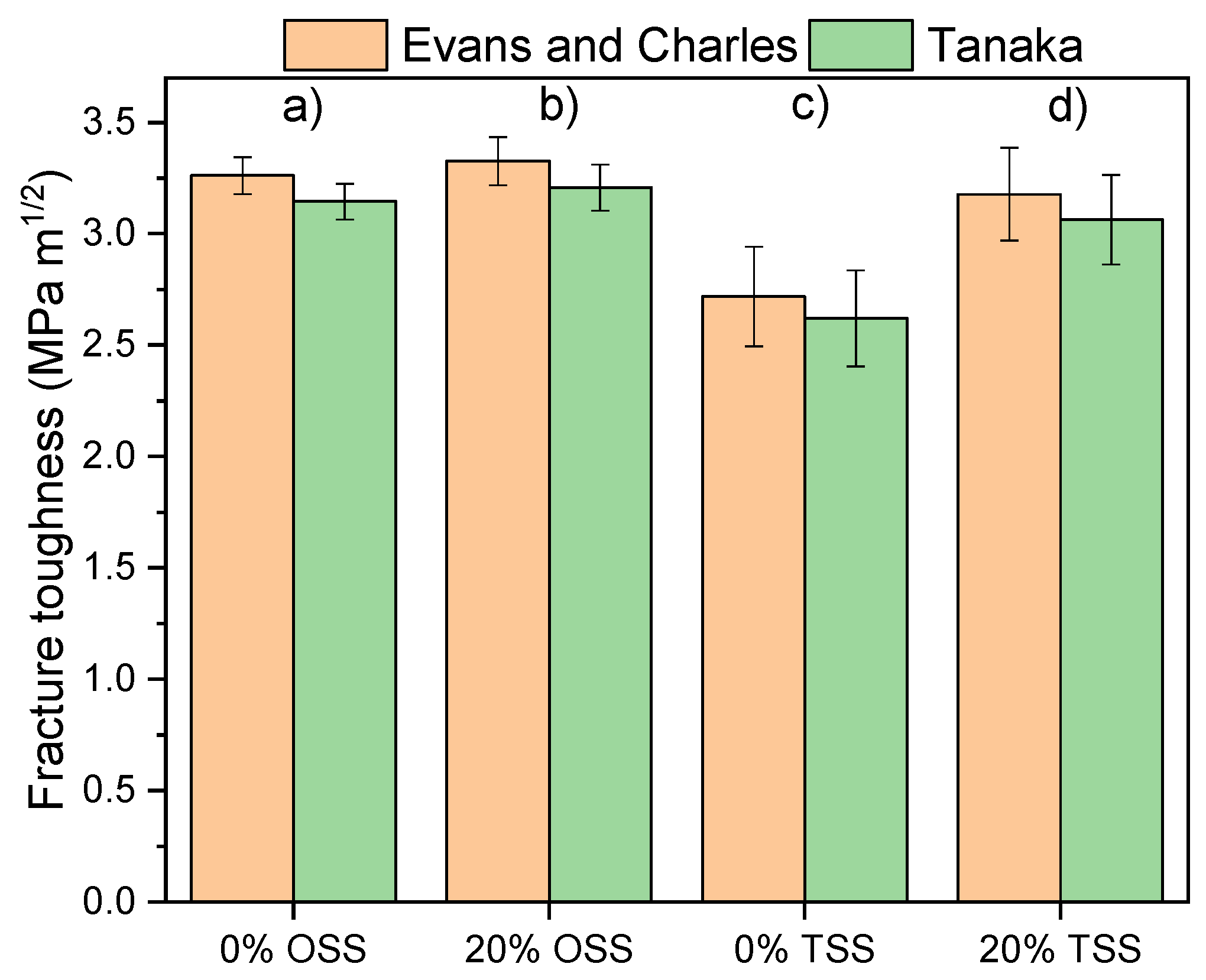
2.4. Microstructural and Mechanical Characterization

The apparent density of sintered samples was determined according to the Archimedes principle by using a density meter (JP703C, Mettler-Toledo GmbH, Greifensee, Switzerland) using water as immersion medium. The theoretical density of 3.980 g cm−3 was taken as a referent value for the relative density calculations of sintered alumina samples [20]. Furthermore, the alumina samples containing and lacking WAP sintered at optimal conditions were characterized by microstructural analysis. The samples were ground by a Struers Rotopol-11, Struers, USA, machine to obtain the polished surface. Firstly, the diamond plates from larger to finer granulation (MD-Piano 220, MD-Piano 1200, MD-Largo) were used, followed by additions of 9 μm, and finally 3 μm, diamond paste on MD-Dac plate. Afterwards, ceramic samples were thermally etched and coated with gold to obtain micrographs through field emission scanning electron microscopy (FESEM) analysis (FEI Helios Nanolab 650, Thermo Fisher, Waltham, MA, USA). The line intercept method [21] was performed when measuring at least 500 grains/per sample to determine average grain sizes (AVGs).
The hardness values were determined according to ASTM C1327-15(2019) by the Vickers method (HV10), which was performed by applying a load of 98.1 N in the indentation time of 10 s at least 5 times per sample using a hardness tester (Innovatest, Nexus 7500, Maastricht, The Netherlands). The dimensions of the corresponding indentations and subsequent crack lengths were processed by an optical microscope (Carl Zeiss, Axio Imager Z1m, Oberkochen, Germany). The obtained lengths were also used to determine fracture toughness (KIC). Numerous mathematical models were proposed for the determination of fracture toughness by using the Vickers indentation fracture (IF) method [22,23,24]. The developed mathematical models enable the calculation of fracture toughness (KIC) by relating to cracks formed in the material during hardness testing as given by Equation (2):
K IC = β 0   ×   E / H 1 / 2   ×   P / c 3 / 2
where β0 is the parameter which value depends on the proposed mathematical model, E is the elasticity modulus, H is the measured Vickers hardness of the material, P is the applied load during the hardness testing, and c is the average crack length measured from the center of the indentation imprint [25]. In this research, the fracture toughness of the sintered alumina ceramics samples was computed using Evans and Charles’s [26] Equation (3) as well as Tanaka’s [27] Equation (4):
K IC = 0.0752   ×   P / c 3 / 2
K IC = 0.0725   ×   P / c 3 / 2

3. Results and Discussion

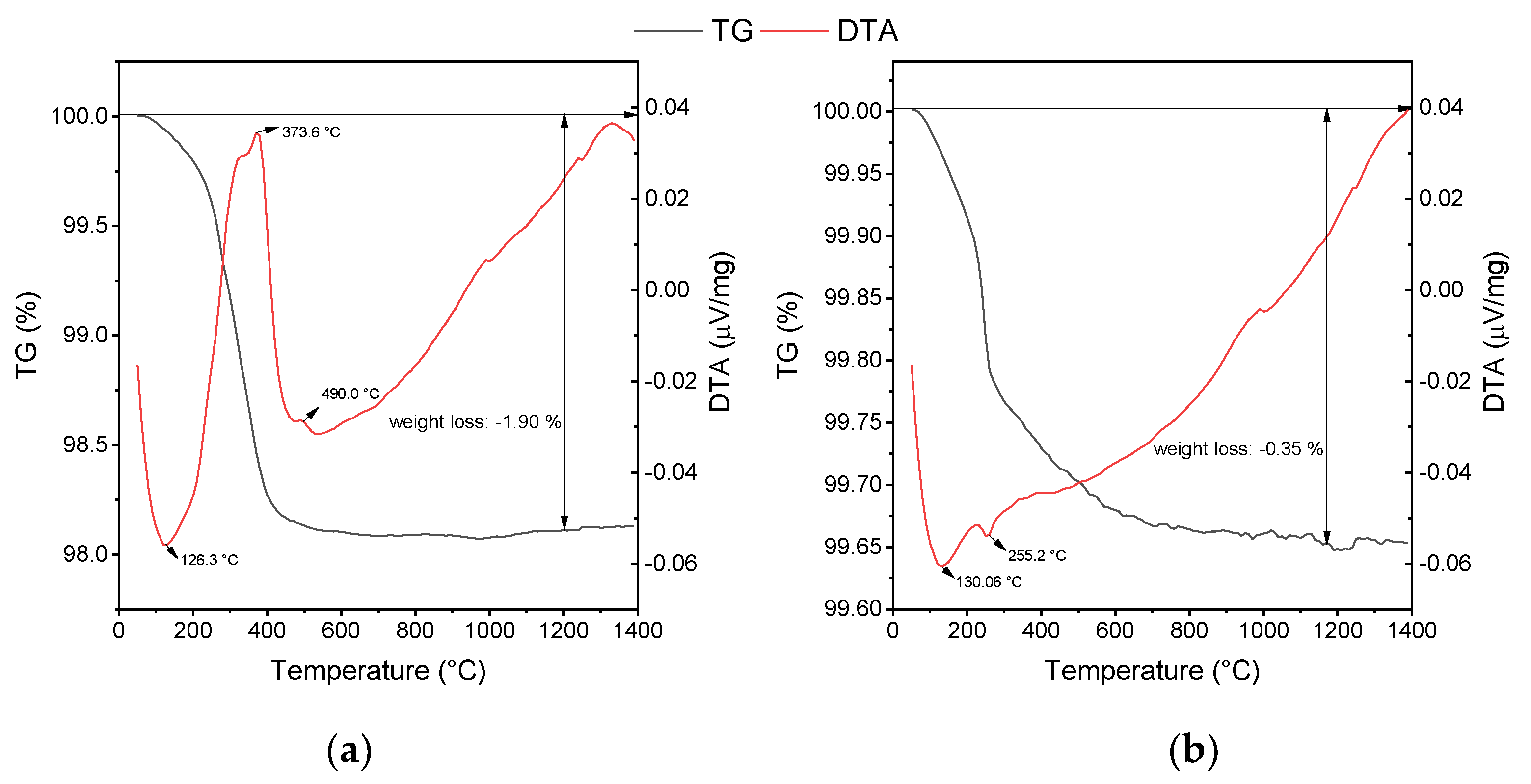
3.1. Thermal Analysis of Alumina Powders

Thermogravimetry/differential thermal analysis (TG/DTA) is the most frequently used method of thermal analysis for determining the organic and inorganic content of various materials. Figure 1 illustrates the effect of increasing temperature on the weight loss of the as-received WAP and commercial alumina powder. All weight changes happened during heating cycle until 1400 °C were reached. The total weight loss of the WAP was around 2 wt. % as a result of water evaporation close to 130 °C and thermal degradation of present organic compounds with increasing temperature (Figure 1a). More precisely, the weight loss was observed at 373.6 °C and 490 °C due to the thermal decomposition of organic additives [28]. A further increase in temperature did not show any weight loss of the WAP. Negligible weight loss of commercial alumina powder was recorded at 130 °C due to a small amount of moisture, and some hydroxides at 255 °C [29] (Figure 1b). Additionally, a slight decrease in weight above of 500 °C could be contributed to transient alumina dihydroxylation [30,31]. The small moisture content of 0.35 wt. % is attributed to the hygroscopic nature of the ceramic powder.
Dilatometric curves were recorded for alumina containing 20 dwb. % of WAP, sintered at favorable TSS conditions (Figure 2). The onset sintering, i.e., densification temperature of about 900 °C is visible. The derivative curve is bimodal, demonstrating firstly a slower shrinkage, followed by a more pronounced one. The first shrinkage could be related to continued decomposition of some hydroxides (Figure 1b) with the increase in temperature, hence the transition from δ to θ to α-alumina, which occurs between 1050 and 1200 °C [32,33,34]. The pronounced shrinkage was attributed to the annihilation of pores on the account of grain boundary diffusion at lower temperatures of the second sintering step [35]. A total linear shrinkage of about 9% was determined.

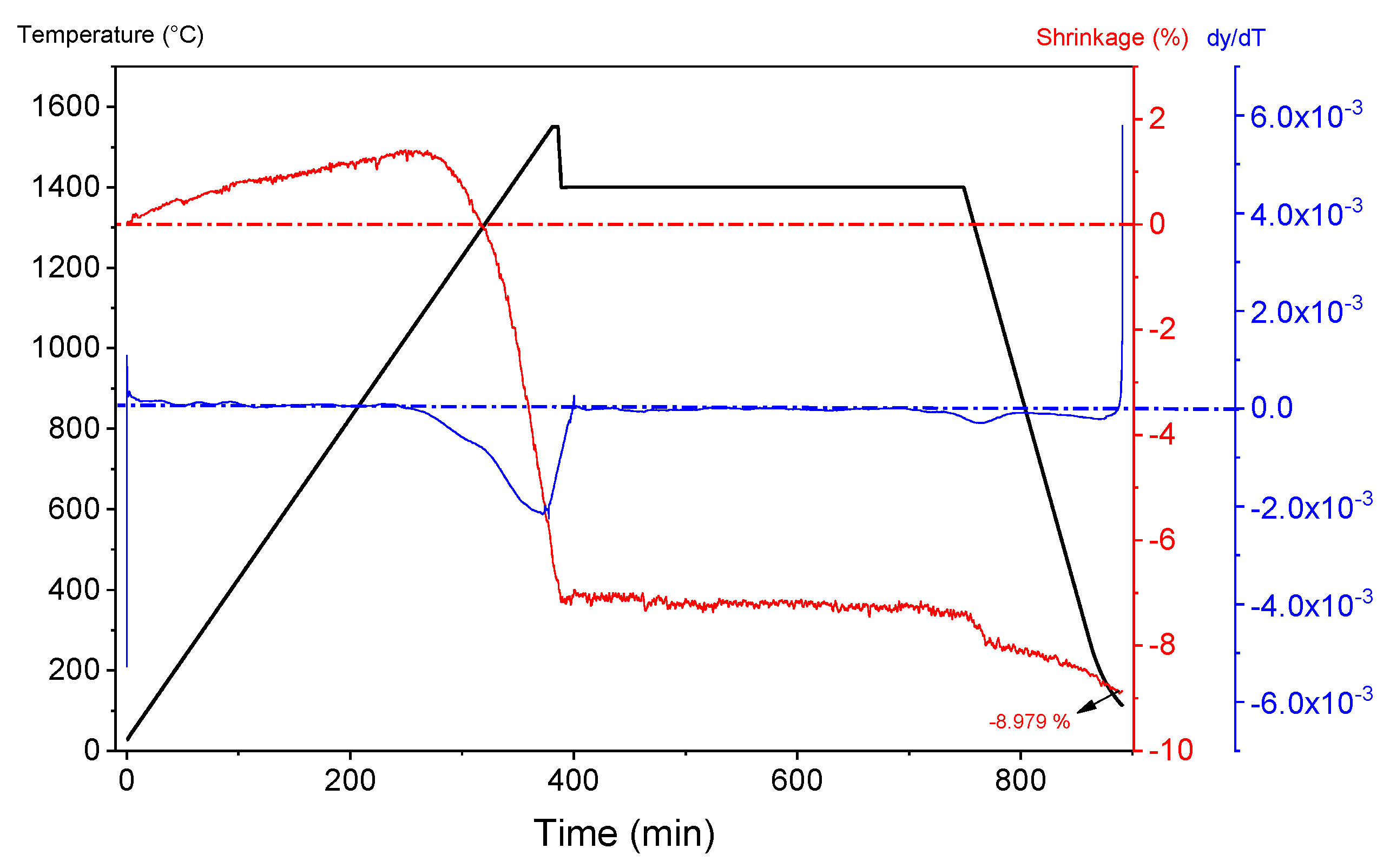
3.2. Determination of Two-Step Sintering Conditions

The apparent density which was achieved for different TSS conditions was the monitored response (Table 3). Additionally, the variation of the observed responses with the change of independent variables (TSS conditions) is presented. The experimental values of the apparent density were fitted to the polynomial second-order model to obtain the most adequate regression equations. The predicted responses were calculated from the following regression equation:
Y   ( density ,   g   cm 3 ) = 2.93768 + 0.000646   ×   X 1 + 0.075958   ×   X 2 + 0.008292   ×   X 3   5.33   ×   10 5   ×   X 1   ×   X 2     0.000792   ×   X 2   ×   X 3
where:
  • X1 is the temperature of the second sintering step (°C),
  • X2 is the heating rate (°C min−1),
  • X3 is the holding time (h).
The presented regression Equation (5) describes the relationship between the independent variables and the response, which is the apparent density of the sintered samples at various TSS conditions.
The significance, goodness of fit, and the coefficients of determination for the developed model were determined by the analysis of variance (ANOVA), as presented in Table 4.
The F-test and the associated p-values (p < 0.05) were determined for the developed model [36,37]. The F-value of 20.45 and the appropriate p = 0.001 suggest that the reduced quadratic model of the density response is a significant model. Furthermore, the determined F-value (0.4473) for the model lack of fit was insignificant (p >> 0.05), which validates the developed model. The satisfactory values for the coefficient of determination R2 = 0.9191 and the adjusted coefficient of determination R Adj . 2 = 0.8742 were determined. The values do not differ substantially, which is a consequence of excluding the nonsignificant quadratic terms from the developed model. The obtained coefficients of determination indicate that the reduced form of the developed model can be used to describe the relationship between the monitored apparent density and applied TSS conditions. The coefficient of variation of the model (C.V. = 0.1183%) strongly suggests a high precision of the experimental values. Additionally, the adequate precision ratio was 15.025, which suggests that the developed model can be applied to the entire design area.
The significance of model terms from Equation (5) indicates (Table 4) the significant terms (p < 0.05) are X1 and X3, and the quadratic interaction X1X2. Other model terms showed less effect (X2X3, p < 0.1) or an insignificant effect (X2, p > 0.1) on the apparent density.

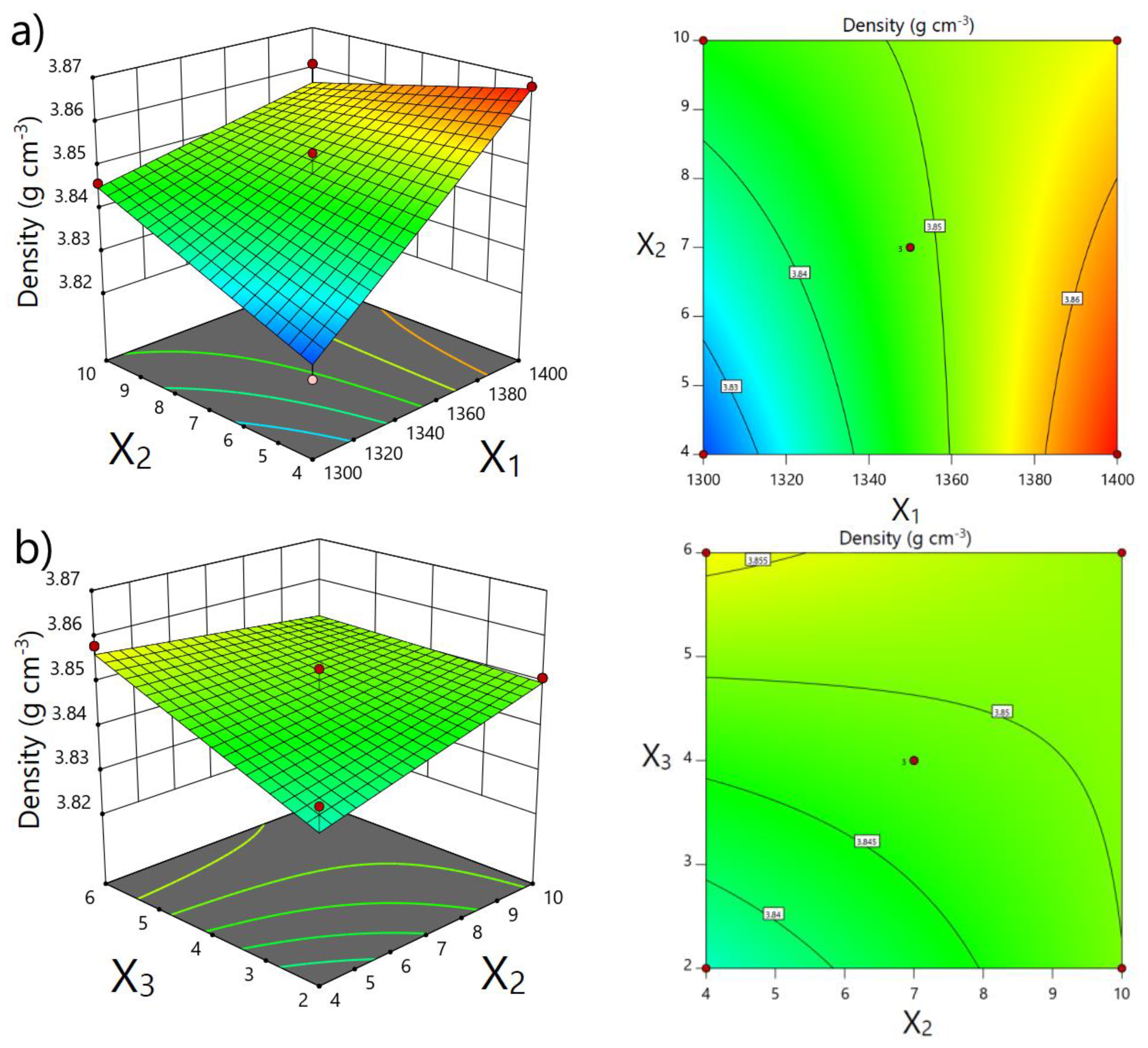
3.3. Interactive Effects of TSS Conditions on Apparent Density

The effects of the temperature of the second sintering step, heating rate, and holding time on the apparent density of sintered samples were depicted using 3D response surface and contour plots (Figure 3a,b). The plots were generated by keeping constant one variable at center level (0), while the remaining two variables were continuous in the investigated range to visualize their effect on the apparent density.
The temperature of the second sintering step showed the most significant effect on the increase of the apparent density of the sintered samples. The density values increased by increasing temperature T2 from 1300 °C to 1400 °C. The third independent variable, X3, the holding time at temperature T2, also had a significant effect on the obtained densities. It can be clearly seen that the achieved density is higher with increasing holding time, although the incline in the apparent density in the plots is not as obvious as in the plot for temperature T2. The change in heating rates in the investigated range did not affect density values.
The favorable conditions of TSS, determined to obtain the maximal apparent density of the sintered samples, are as follows: the temperature of the second sintering step of 1400 °C, the heating rate of 4 °C min−1, and holding time of 5 h. The holding time of 5 h was determined as favorable because the difference in the achieved density between applied holding times of 5 and 6 h is negligible. Therefore, from an economic point of view, it is justified to apply a holding time of 5 h (Figure 3b). The validation of the predicted favorable conditions was conducted by sintering at least three samples. The obtained density for TSS at determined favorable conditions was 3.862 g cm−3 ± 0.007 g cm−3 (~97 % TD) for samples containing 20 dwb. % of WAP, and 3.820 g cm−3 ± 0.020 g cm−3 (~96 % TD) for samples lacking WAP, respectively. Both densities are in good agreement with the predicted value of 3.869 g cm−3 ± 0.006 g cm−3. The reported density of alumina achieved by TSS varies from to 96 % TD [19] to 99 % TD [11].

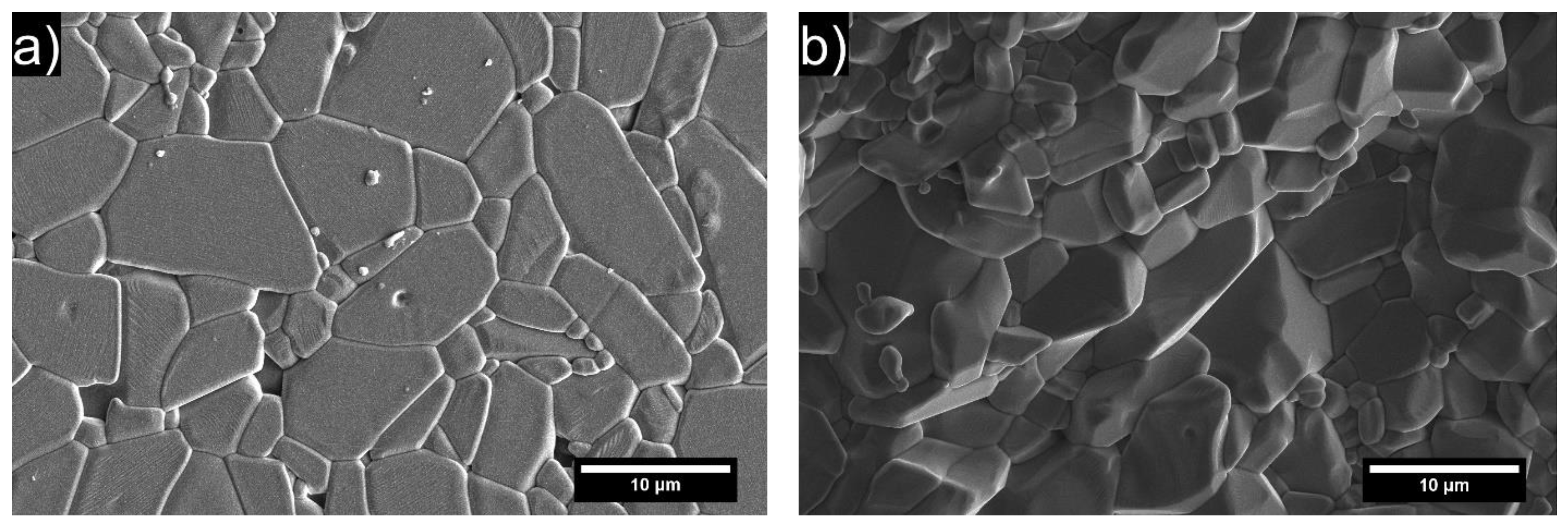
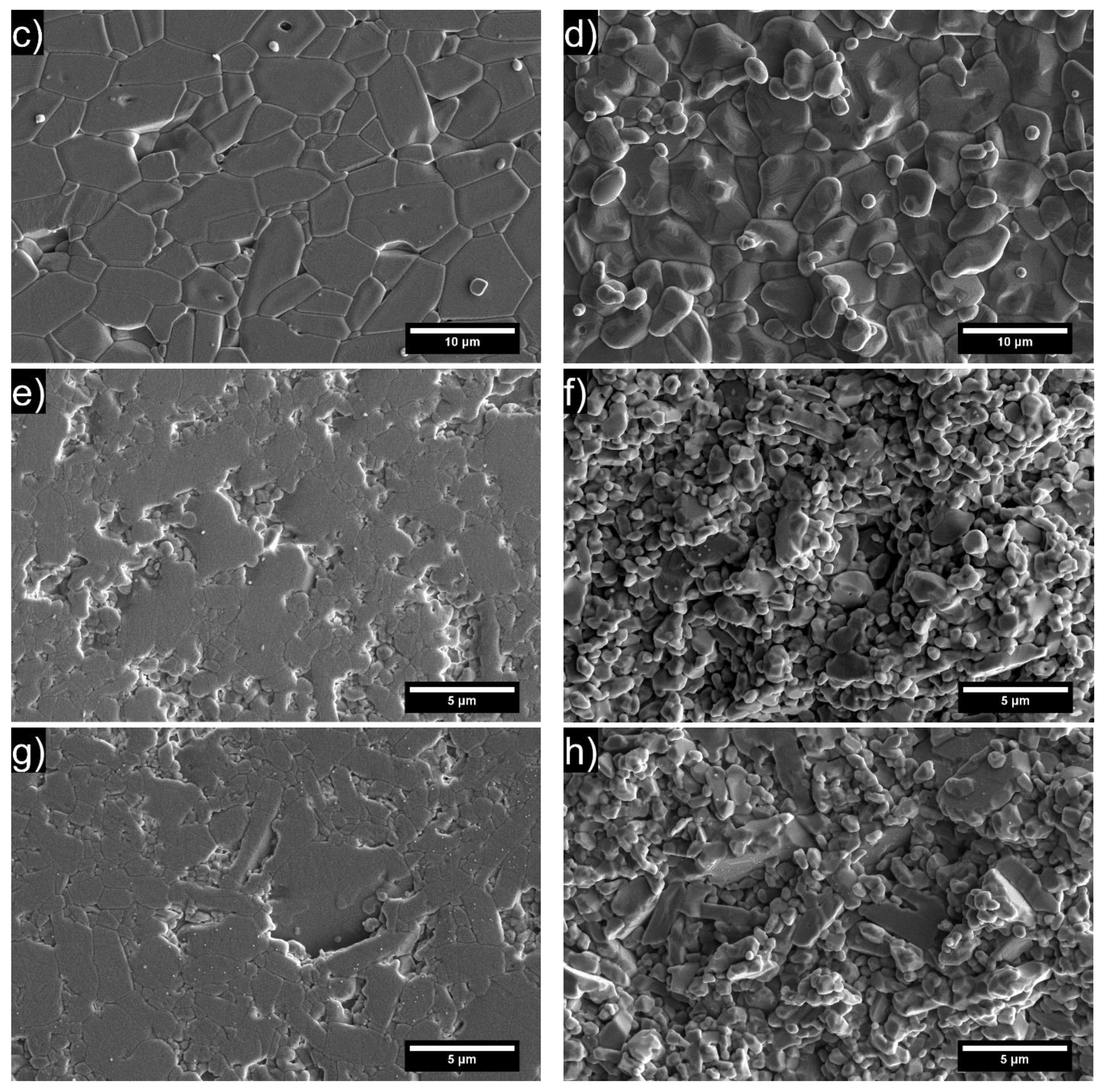
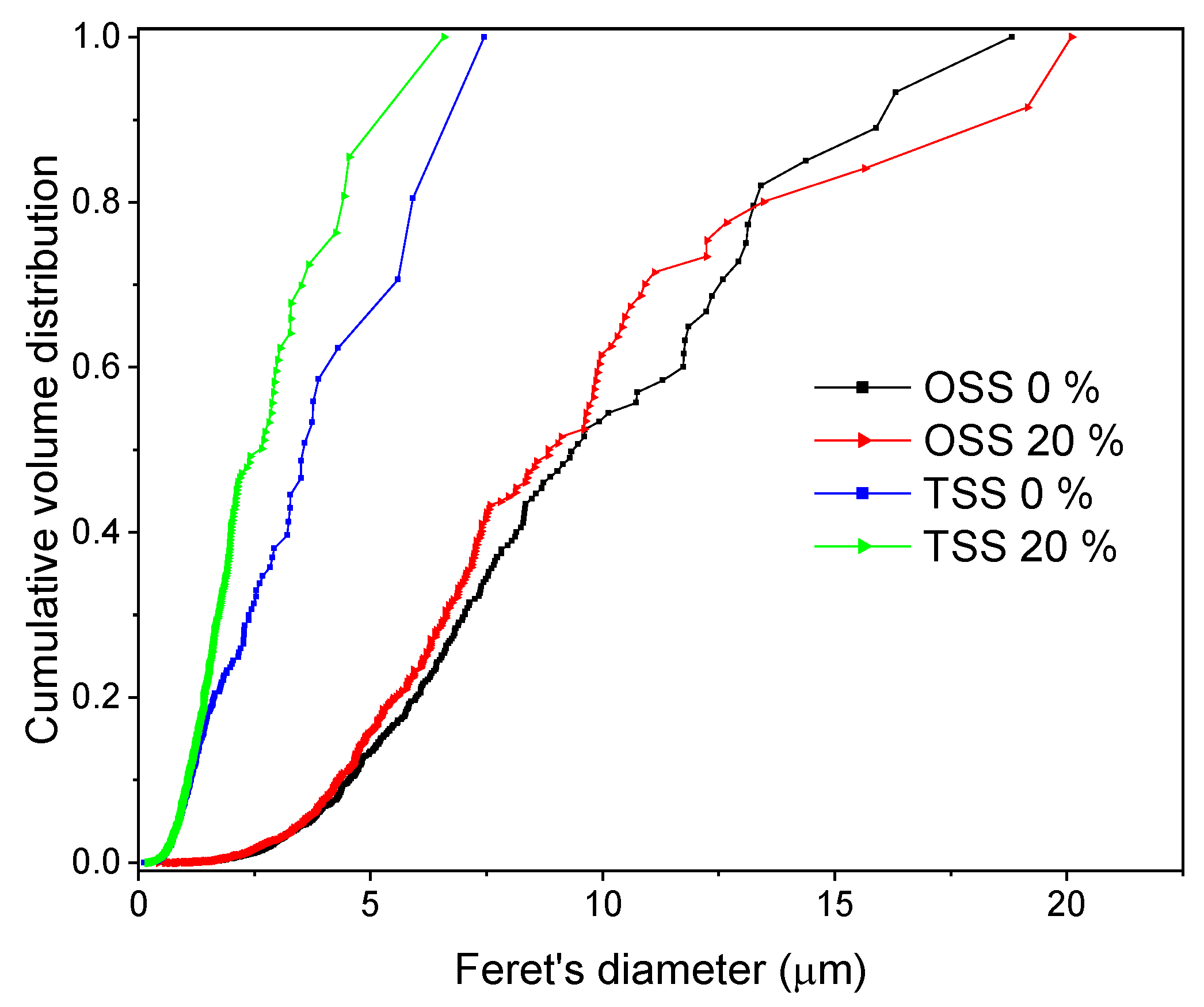
3.4. Microstructure of Sintered Alumina

The obtained FESEM micrographs of samples sintered by TSS at favorable conditions were compared with micrographs obtained by conventional OSS (Figure 4). The presented microstructures are relatively dense, while sporadic intergranular pores were observed. The addition of WAP has positively affected the obtained microstructures, resulting in slightly increased density values and reduced average grain size, as presented in Table 5. The organic binders present in the WAP (Figure 1) contributed to higher relative/green densities of alumina samples with the addition of WAP.
The microstructures with substantially smaller grains can be noticed for samples sintered by TSS regardless of WAP content. This is clearly presented in Figure 5, with all data listed in Table 5. In addition to the reduced grain growth, larger oriented plate-like particles served as templates for the generation of similarly oriented grains during the sintering process, as can be observed from the elongated grains in TSS micrographs (Figure 4e,g). The thermal gradients contributed to texturing via preferential growth of aligned grains, thus resulting in partially textured ceramics [38,39]. Furthermore, micrographs showing fracture surfaces of TSS samples exhibit crack propagation along boundaries of grain aggregates 3–5 μm in size formed due to favorable TSS mode. The “embossed” fracture surface comprising cleavage facets of elongated grains is evidence of high cohesion between grains merged into aggregates and, as a result, comparatively high fracture toughness of the TSS/ 20 dwb. % WAP material. (Figure 4f,h). The fracture surface micrographs of OSS samples revealed transgranular crack propagation without any visible crack deflection (Figure 4b,d).
The cumulative grain size distribution (GSD) for each composition shows that the narrowest distributions were achieved when TSS was used for sintering of alumina samples (Figure 5). The microstructures obtained by this sintering procedure showed a finer average grain distribution with partial consolidation (higher porosity) of the microstructure (Figure 4, Table 5). The widest distribution of grain sizes was determined for the microstructure obtained by the OSS process with a higher degree of consolidation. From the presented cumulative volume distribution curves, the positive effect of the addition of WAP, which contributed to even further narrowing the grain size distribution (GSD) of alumina samples sintered by the TSS process, can be seen. The effect of the addition of WAP on GSD of samples sintered by the OSS process was less obvious but was still present. Furthermore, it was determined that 80 vol. % of grains sintered by TSS had a diameter smaller than 5.91 μm and 4.42 μm, for samples lacking WAP and containing 20 dwb. % of WAP, respectively. The curves of GSD for samples sintered by OSS demonstrated larger grains compared to TSS, with 80 vol. % of grains smaller than 13.25 μm for the samples with the addition of WAP, and 13.45 μm for samples without the addition of WAP.
The determined Vickers hardness (HV10) were ~14.7 GPa for OSS 0 and ~14.5 GPa for OSS 20. Lower values of Vickers hardness, ~10.2 GPa for TSS 0 and ~12.1 GPa for TSS 20, were obtained due to higher porosity of TSS samples compared to OSS samples. Lower densities obtained by TSS resulted in lower hardness values compared to conventionally sintered samples, although a significant reduction of average grain size was achieved (Table 5). The applied conventional sintering method with a high sintering temperature of 1650 °C boosted the consolidation rate, which led to an increase of AGS with more pronounced grain boundaries. It was expected that the addition of the WAP would result in finer microstructures due to the increased MgO content (Table 1). The stronger effect of WAP addition is less noticeable due to magnesium spinel, which was used as a sintering additive during the preparation of alumina green bodies.
The indentation toughness (KIC) values were computed according to Evans/Charles [26] and Tanaka [27] median crack models (Figure 6). A slight increase in fracture toughness with the addition of WAP was registered when OSS was used. A larger increase in fracture toughness was observed when the samples containing WAP were sintered using TSS. The lowest values in fracture toughness were observed for samples TSS 0, which had the highest porosity. The samples TSS 20 are on par with OSS samples despite the higher porosity of TSS 20 samples. This can be explained by promoted crack deflection due to textured microstructure (Figure 4e–h), which subsequently increased fracture toughness of TSS 20 samples [40]. In general, all calculated KIC values were in the range from 2.7 MPa m1/2 to 3.5 MPa m1/2, which is in agreement with the literature values for alumina engineering ceramics [41,42].

4. Conclusions

The favorable conditions for TSS of alumina samples containing up to 20 dwb. % of WAP were determined. The TSS conditions of T1 = 1550 °C, t1 = 5 min, T2 = 1400 °C, t2 = 5 h with the applied heating rate of 4 °C min−1 were used to achieve the maximal apparent density in the investigated range. The obtained sintered samples were compared with samples without WAP and with samples sintered by conventional OSS. The significant sintering parameters were the temperature of the second sintering step (T2) and holding time at T2 (t2), while the change in heating rate was insignificant in the investigated range. The achieved relative densities (~97%) were lower compared to OSS (~98%) because of lower T2, which is necessary to avoid grain growth. In addition, lower relative densities were obtained for alumina samples without WAP due to sintering additives present in the waste alumina powder. Generally, regardless of WAP content, the samples sintered by TSS demonstrate reduced average grain size of around 1 μm with noticeable elongation of grains (texturing) and higher porosity compared to the conventionally sintered samples with AGS of around 4 μm. This resulted in decreased hardness values (~10.2 GPa for TSS 0 and ~12.1 GPa for TSS 20) and in slightly changed indentation fracture toughness values of ~3.2 MPa m1/2 for TSS 20, as compared to the conventionally sintered samples. The addition of WAP did not result in degradation of mechanical properties, which suggests the feasibility of recycling WAP as secondary raw material in ceramic manufacturing. However, some limitations for alumina-containing WAP may be noted. In particular, the limited use of such material can be in applications where strong requirements are placed on the color or other surface features of ceramic products, as the resulting microstructure may still cause the effects of changing the color of the product and other factors.

Author Contributions

Conceptualization, M.V., L.Ć. and I.Ž.; methodology, M.V., A.K. and L.Ć.; software, M.V.; validation, A.K., L.Ć. and I.Ž.; formal analysis, A.K., L.Ć. and I.Ž.; investigation, M.V.; resources, L.Ć. and A.K.; data curation, M.V., A.K., L.Ć. and I.Ž.; writing—original draft preparation, M.V.; writing—review and editing, A.K., I.Ž. and L.Ć.; visualization, M.V.; supervision, I.Ž., L.Ć. and A.K.; project administration, L.Ć.; funding acquisition, L.Ć. and A.K. All authors have read and agreed to the published version of the manuscript.

Funding

This work was supported by the Croatian Science Foundation under the project [IP-2016-06-6000]: Monolithic and Composite Advanced Ceramics for Wear and Corrosion Protection (WECOR) and by the Slovenian National Research Programme [P2-0087]: Ceramics and Complementary Materials for Advanced Engineering and Biomedical Applications.

Institutional Review Board Statement

Not applicable.

Informed Consent Statement

Not applicable.

Data Availability Statement

The authors declare that all data supporting the findings of this study are available within the article.

Conflicts of Interest

The authors declare no conflict of interest.

References

  1. Directive (EU) 2018/851 of the European Parliament and of the Council of 30 May 2018 amending Directive 2008/98/EC on waste. Available online: https://eur-lex.europa.eu/legal-content/EN/TXT/?uri=celex%3A32018L0851 (accessed on 11 July 2022).
  2. Kučerová, M.; Mĺkva, M.; Sablik, J.; Gejguš, M. Eliminating waste in the production process using tools and methods of industrial engineering. Prod. Eng. Arch. 2015, 9, 30–34. [Google Scholar] [CrossRef]
  3. Fernandez de Arroyabe, J.C.; Arranz, N.; Schumann, M.; Arroyabe, M.F. The development of CE business models in firms: The role of circular economy capabilities. Technovation 2021, 106, 102292. [Google Scholar] [CrossRef]
  4. Mohammadhosseini, H.; Lim, N.H.A.S.; Tahir, M.M.; Alyousef, R.; Samadi, M.; Alabduljabbar, H.; Mohamed, A.M. Effects of Waste Ceramic as Cement and Fine Aggregate on Durability Performance of Sustainable Mortar. Arab. J. Sci. Eng. 2020, 45, 3623–3634. [Google Scholar] [CrossRef]
  5. Ruys, A. Introduction to Alumina Ceramics. In Alumina Ceramics; Woodhead Publishing: Sawston, UK, 2019; pp. 1–37. ISBN 9780081024423. [Google Scholar]
  6. Vukšić, M.; Žmak, I.; Ćurković, L.; Ćorić, D.; Jenuš, P.; Kocjan, A. Evaluating recycling potential of waste alumina powder for ceramics production using response surface methodology. J. Mater. Res. Technol. 2021, 11, 866–874. [Google Scholar] [CrossRef]
  7. Lóh, N.J.; Simão, L.; Faller, C.A.; De Noni, A.; Montedo, O.R.K. A review of two-step sintering for ceramics. Ceram. Int. 2016, 42, 12556–12572. [Google Scholar] [CrossRef]
  8. Salernitano, E.; Grilli, S.; Mazzanti, F.; Fabbri, P.; Magnani, G. Definition of the parameters for the densification of ceramics by two-step solid state sintering. Open Ceram. 2022, 9, 100242. [Google Scholar] [CrossRef]
  9. Makireddi, D.; Ghuge, V.D.; Thakare, G.; Thawre, M.M. Application of two-step sintering cycle to 20–30 nm α-Al2O3 compacts to investigate microstructure, hardness, strength, density and corundum formation. Mater. Res. Express 2020, 6, 1250e1. [Google Scholar] [CrossRef]
  10. Maca, K.; Pouchly, V.; Zalud, P. Two-Step Sintering of oxide ceramics with various crystal structures. J. Eur. Ceram. Soc. 2010, 30, 583–589. [Google Scholar] [CrossRef]
  11. Bodišová, K.; Galusek, D.; Švančárek, P.; Pouchlý, V.; Maca, K. Grain growth suppression in alumina via doping and two-step sintering. Ceram. Int. 2015, 41, 11975–11983. [Google Scholar] [CrossRef]
  12. Galusek, D.; Ghillányová, K.; Sedláček, J.; Kozánková, J.; Šajgalík, P. The influence of additives on microstrucutre of sub-micron alumina ceramics prepared by two-stage sintering. J. Eur. Ceram. Soc. 2012, 32, 1965–1970. [Google Scholar] [CrossRef]
  13. Isobe, T.; Ooyama, A.; Shimizu, M.; Nakajima, A. Pore size control of Al2O3 ceramics using two-step sintering. Ceram. Int. 2012, 38, 787–793. [Google Scholar] [CrossRef]
  14. Bodišová, K.; Šajgalík, P.; Galusek, D.; Švančárek, P. Two-Stage Sintering of Alumina with Submicrometer Grain Size. J. Am. Ceram. Soc. 2007, 90, 330–332. [Google Scholar] [CrossRef]
  15. Vukšić, M.; Žmak, I.; Ćurković, L.; Kocjan, A. Spark plasma sintering of dense alumina ceramics from industrial waste scraps. Open Ceram. 2021, 5, 100076. [Google Scholar] [CrossRef]
  16. Vukšić, M.; Žmak, I.; Ćurković, L.; Ćorić, D. Effect of Additives on Stability of Alumina—Waste Alumina Suspension for Slip Casting: Optimization Using Box-Behnken Design. Materials 2019, 12, 1738. [Google Scholar] [CrossRef] [Green Version]
  17. Myers, H.R.; Montgomery, C.D.; Anderson-Cook, M.C. Response Surface Methodology: Process and Product Optimization Using Designed Experiments, 4th ed.; Wiley: Hoboken, NJ, USA, 2016; ISBN 978-1-118-91601-8. [Google Scholar]
  18. Lóh, N.J.; Simão, L.; Jiusti, J.; De Noni Jr., A.; Montedo, O.R.K. Effect of temperature and holding time on the densification of alumina obtained by two-step sintering. Ceram. Int. 2017, 43, 8269–8275. [Google Scholar] [CrossRef]
  19. Lóh, N.J.; Simão, L.; Jiusti, J.; Arcaro, S.; Raupp-Pereira, F.; De Noni, A.; Montedo, O.R.K. Densified alumina obtained by two-step sintering: Impact of the microstructure on mechanical properties. Ceram. Int. 2020, 46, 12740–12743. [Google Scholar] [CrossRef]
  20. Zygmuntowicz, J.; Tomaszewska, J.; Żurowski, R.; Wachowski, M.; Piotrkiewicz, P.; Konopka, K. Zirconia–Alumina Composites Obtained by Centrifugal Slip Casting as Attractive Sustainable Material for Application in Construction. Materials 2021, 14, 250. [Google Scholar] [CrossRef]
  21. Althyabat, S.; Miles, N. An improved estimation of size distribution from particle profile measurements. Powder Technol. 2006, 166, 152–160. [Google Scholar] [CrossRef]
  22. Kulyk, V.V.; Duriagina, Z.A.; Vasyliv, B.D.; Vavrukh, V.I.; Lyutyy, P.Y.; Kovbasiuk, T.M.; Holovchuk, M.Y. Effects of Yttria content and sintering temperature on the microstructure and tendency to brittle fracture of yttria-stabilized Zirconia. Arch. Mater. Sci. Eng. 2021, 109, 65–79. [Google Scholar] [CrossRef]
  23. Liang, K.M.; Orange, G.; Fantozzi, G. Evaluation by indentation of fracture toughness of ceramic materials. J. Mater. Sci. 1990, 25, 207–214. [Google Scholar] [CrossRef]
  24. Ćorić, D.; Majić Renjo, M.; Ćurković, L. Vickers indentation fracture toughness of Y-TZP dental ceramics. Int. J. Refract. Met. Hard Mater. 2017, 64, 14–19. [Google Scholar] [CrossRef]
  25. Roebuck, B.; Bennett, E.G.; Lay, L.A.; Morrell, R. The Measurement of Palmqvist Toughness for Hard and Brittle Materials; National Physical Laboratory: Teddington, UK, 2008. [Google Scholar]
  26. Evans, A.G.; Charles, E.A. Fracture Toughness Determinations by Indentation. J. Am. Ceram. Soc. 1976, 59, 371–372. [Google Scholar] [CrossRef]
  27. Tanaka, K. Elastic/plastic indentation hardness and indentation fracture toughness: The inclusion core model. J. Mater. Sci. 1987, 22, 1501–1508. [Google Scholar] [CrossRef]
  28. Trindade, W.; de Matos Chagas, C.F.; Gomes, A.V.; Louro, L.H.L. Organic Binder Burnout in Alumina Processing. In Proceedings of the Materials Science Forum; Trans Tech Publications Ltd.: Bäch, Switzerland, 2014; Volume 798–799, pp. 653–658. [Google Scholar] [CrossRef]
  29. Vasile, B.S.; Dobra, G.; Iliev, S.; Cotet, L.; Neacsu, I.A.; Nicoara, A.I.; Surdu, V.A.; Boiangiu, A.; Filipescu, L. Thermally Activated Al(OH)3: Part I—Morphology and Porosity Evaluation. Ceramics 2021, 4, 265–277. [Google Scholar] [CrossRef]
  30. Krupa, P.; Malinarič, S. Thermal properties of green alumina porcelain. Ceram. Int. 2015, 41, 3254–3258. [Google Scholar] [CrossRef]
  31. Nakonieczny, D.S.; Kern, F.; Dufner, L.; Dubiel, A.; Antonowicz, M.; Matus, K. Effect of Calcination Temperature on the Phase Composition, Morphology, and Thermal Properties of ZrO2 and Al2O3 Modified with APTES (3-aminopropyltriethoxysilane). Materials 2021, 14, 6651. [Google Scholar] [CrossRef]
  32. Boumaza, A.; Favaro, L.; Lédion, J.; Sattonnay, G.; Brubach, J.B.; Berthet, P.; Huntz, A.M.; Roy, P.; Tétot, R. Transition alumina phases induced by heat treatment of boehmite: An X-ray diffraction and infrared spectroscopy study. J. Solid State Chem. 2009, 182, 1171–1176. [Google Scholar] [CrossRef]
  33. Lamouri, S.; Hamidouche, M.; Bouaouadja, N.; Belhouchet, H.; Garnier, V.; Fantozzi, G.; Trelkat, J.F. Control of the γ-alumina to α-alumina phase transformation for an optimized alumina densification. Boletín la Soc. Española Cerámica y Vidr. 2017, 56, 47–54. [Google Scholar] [CrossRef] [Green Version]
  34. Palmero, P.; Lombardi, M.; Montanaro, L.; Azar, M.; Chevalier, J.; Garnier, V.; Fantozzi, G. Effect of heating rate on phase and microstructural evolution during pressureless sintering of a nanostructured transition alumina. Int. J. Appl. Ceram. Technol. 2009, 6, 420–430. [Google Scholar] [CrossRef]
  35. Sutharsini, U. Two-Step Sintering of Ceramics. In Sintering of Functional Materials; Thanihaichelvan, M., Ed.; IntechOpen: Rijeka, Croatia, 2018; Chapter 1; ISBN 978-953-51-3757-3. [Google Scholar]
  36. Whitcomb, P.J.; Anderson, M.J. RSM Simplified—Optimizing Process Using Response Surface Methods for Design of Experiments, 2nd ed.; Productivity Press: New York, NY, USA, 2017; ISBN 9781315382326. [Google Scholar]
  37. Landek, D.; Ćurković, L.; Gabelica, I.; Kerolli Mustafa, M.; Žmak, I. Optimization of Sintering Process of Alumina Ceramics Using Response Surface Methodology. Sustainability 2021, 13, 6739. [Google Scholar] [CrossRef]
  38. Messing, G.L.; Poterala, S.; Chang, Y.F.; Frueh, T.; Kupp, E.R.; Watson, B.H.; Walton, R.L.; Brova, M.J.; Hofer, A.K.; Bermejo, R.; et al. Texture-engineered ceramics-Property enhancements through crystallographic tailoring. J. Mater. Res. 2017, 32, 3219–3241. [Google Scholar] [CrossRef] [Green Version]
  39. Zhang, Z.; Duan, X.; Qiu, B.; Yang, Z.; Cai, D.; He, P.; Jia, D.; Zhou, Y. Preparation and anisotropic properties of textured structural ceramics: A review. J. Adv. Ceram. 2019, 8, 289–332. [Google Scholar] [CrossRef] [Green Version]
  40. Hofer, A.K.; Walton, R.; Ševeček, O.; Messing, G.L.; Bermejo, R. Design of damage tolerant and crack-free layered ceramics with textured microstructure. J. Eur. Ceram. Soc. 2020, 40, 427–435. [Google Scholar] [CrossRef]
  41. Auerkari, P. Mechanical and Physical Properties of Engineering Alumina Ceramics; VTT Tiedotteita—Meddelanden—Research Notes BT—Mechanical and Physical Properties of Engineering Alumina ceramics; VTT Technical Research Centre of Finland: Espoo, Finland, 1996; ISBN 951-38-4987-2. [Google Scholar]
  42. Johnson, R. (Ed.) Handbook of Advanced Ceramics and Composites-Defense, Security, Aerospace and Energy Applications; Springer: Cham, Switzerland, 2020; ISBN 978-3-030-16346-4. [Google Scholar]
Figure 1. DTA/TG curves of: (a) waste alumina powder and (b) pure alumina powder.
Materials 15 07840 g001
Figure 2. Dilatometry analysis of alumina containing 20 dwb. % of WAP sintered at optimal TSS conditions.
Materials 15 07840 g002
Figure 3. 3D response surface and contour plots depicting influence of: (a) sintering temperature of second step (X1) and heating rate (X2) and (b) holding time (X3) and heating rate (X2) on apparent density.
Materials 15 07840 g003
Figure 4. FESEM images of alumina surface microstructure. (a) OSS/0 dwb. % WAP; (c) OSS/20 dwb. % WAP; (e) TSS/0 dwb. % WAP; (g) TSS/20 dwb. % WAP and of respective sample fracture surface: (b) OSS/0 dwb. % WAP; (d) OSS/20 dwb. % WAP; (f) TSS/0 dwb. % WAP; (h) TSS/20 dwb. % WAP.
Materials 15 07840 g004aMaterials 15 07840 g004b
Figure 5. Cumulative volume grain size distribution versus Feret’s diameter of sintered samples with different waste alumina content.
Materials 15 07840 g005
Figure 6. The calculated fracture toughness according to median crack models for: (a) OSS/0 dwb. % WAP; (b) OSS/20 dwb. % WAP; (c) TSS/0 dwb. % WAP; (d) TSS/20 dwb. % WAP.
Materials 15 07840 g006
Table 1. Chemical composition of pure and waste alumina powder.
PowderComponentMgOFe2O3SiO2Na2OCaOAl2O3
Purewt. %0.060.020.020.050.01rest
WAP 1wt. %0.100.020.020.080.03rest
1 Obtained after green machining step from industrial facility for alumina ceramics manufacturing.
Table 2. Box–Behnken experimental design for the three levels (−1, 0, and 1) of factor X1 (temperature of the second sintering step), X2 (heating rate), X3 (holding time).
RunTemperature of Second Sintering Step (°C)Heating Rate
(°C min−1)
Holding Time
(h)
CodedActualCodedActualCodedActual
101350−1416
2114000716
301350110−12
4013500704
51140011004
6−11300−1404
71140007−12
80135011016
911400−1404
10−1130011004
11013500704
12013500704
1301350−14−12
14−1130007−12
15−113000716
Table 3. Monitored responses and predicted data of applied BBD.
Box–Behnken Design
RunX1
Temperature of Second
Sintering Step
X2
Heating
Rate
X3
Holding Time
Y
Apparent
Density
(°C)(°C min−1)(h)Experimental (g cm−3)Predicted
(g cm−3)
11350463.8583.856
21400763.8653.867
313501023.8513.850
41350743.8533.848
514001043.8613.856
61300443.8213.824
71400723.8523.856
813501063.8493.851
91400443.8683.868
1013001043.8463.845
111350743.8413.848
121350743.8483.848
131350423.8413.836
141300723.8273.829
151300763.8433.840
Table 4. ANOVA results for fitted regression model of monitored response.
SourceApparent Density Model
Sum of SquaresdfF-Valuep-Value
Model0.0021520.450.0001
X10.0015171.69<0.0001
X20.000012.180.1741
X30.0002130.830.0077
X1X20.000312.660.0066
X2X30.000113.750.0665
Residual0.00029
Lack of fit0.000170.44730.8225
Pure error0.00012 R 2 = 0.9191
Total0.002314 R Adj . 2 = 0.8742
C.V. % = 0.1183Adequate precision = 15.0250
Table 5. Properties of alumina ceramics sintered conventionally and at determined favorable TSS conditions.
Sample IDSintering
Method
WAP
(dwb. %)
T1
(°C)
T2
(°C)
t2
(h)
Green Density
(%)
Relative
Density
(%)
AGS
(µm)
HV10
(GPa)
OSS 0OSS01650-559.43 ± 2.3198.20 ± 0.533.91 ± 2.6514.70 ± 0.45
OSS 20OSS201650-562.77 ± 2.1498.40 ± 0.303.63 ± 2.4914.48 ± 0.30
TSS 0TSS015501400561.01 ± 7.5995.98 ± 0.500.87 ± 0.6610.18 ± 0.34
TSS 20TSS2015501400557.67 ± 3.7597.04 ± 0.180.88 ± 0.6012.10 ± 0.44
Publisher’s Note: MDPI stays neutral with regard to jurisdictional claims in published maps and institutional affiliations.

