
Prediction of Structural Behavior of Continuous Reinforced Concrete Beams with Hybrid CFRP-Steel Bars
Abstract
:1. Introduction
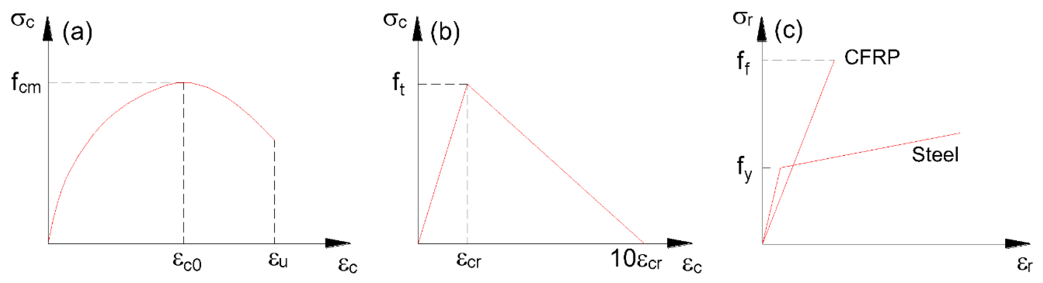
2. Numerical Method
3. Numerical Investigation
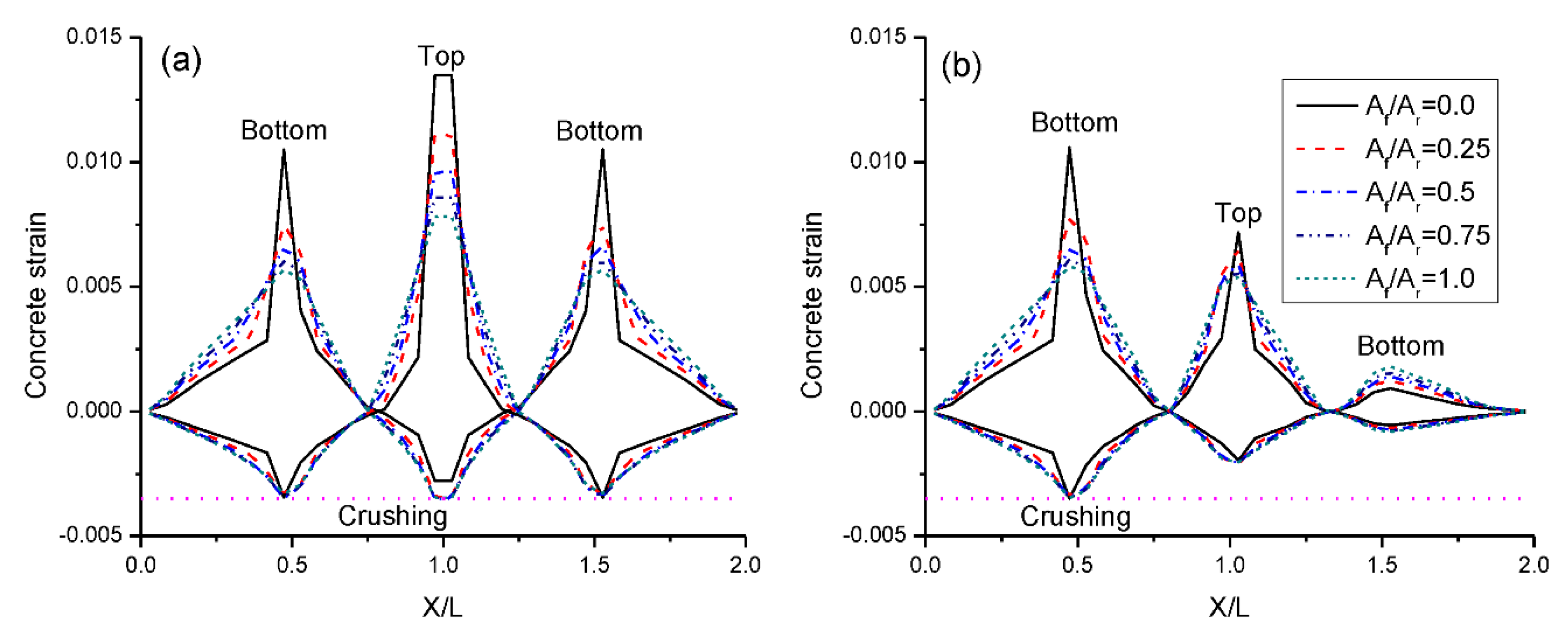
3.1. Failure and Cracking Modes
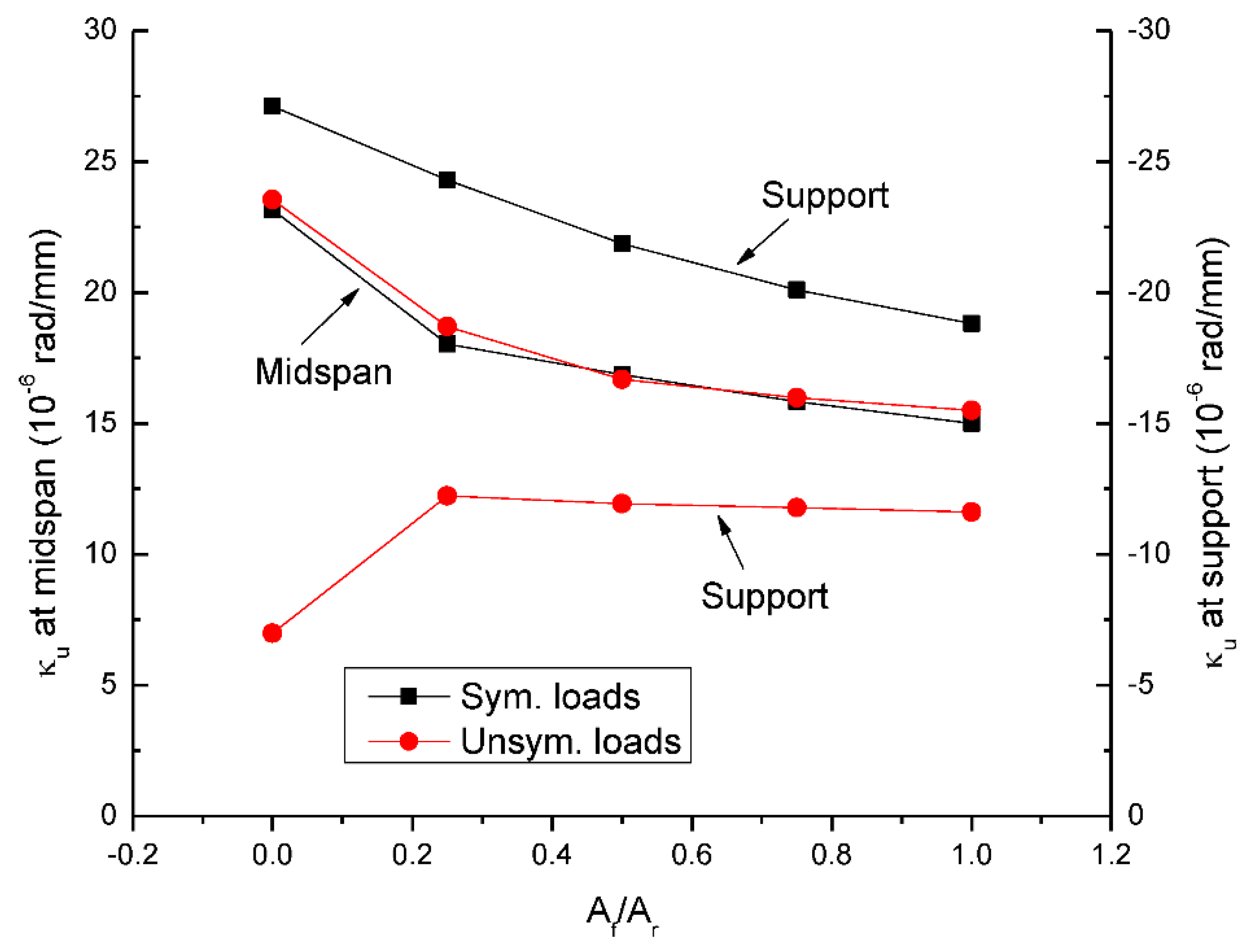
3.2. Moment-Curvature Behavior
3.3. Load-Deflection Behavior
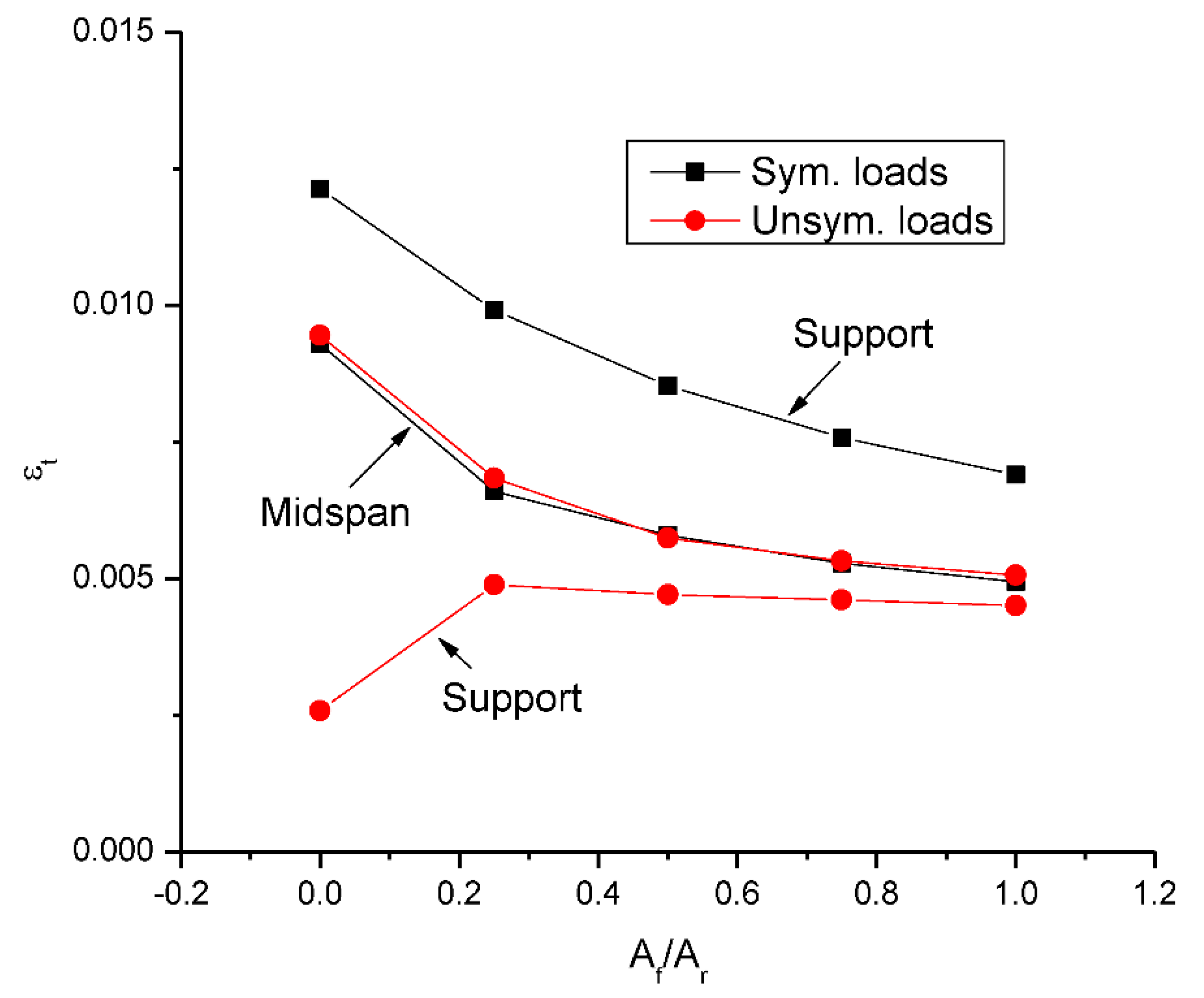
3.4. Strain in Tensile Bars
3.5. Development of Bending Moments
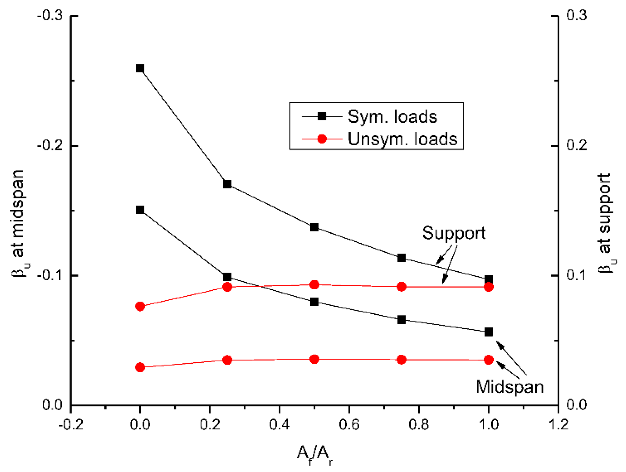
3.6. Moment Redistribution
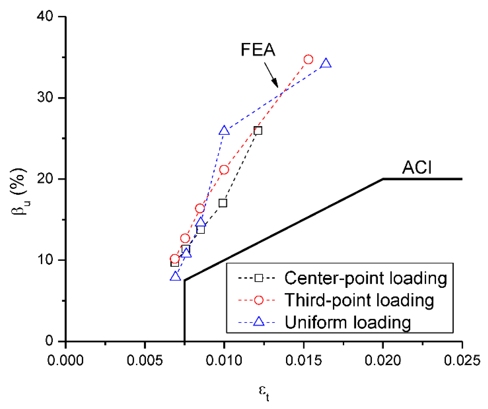
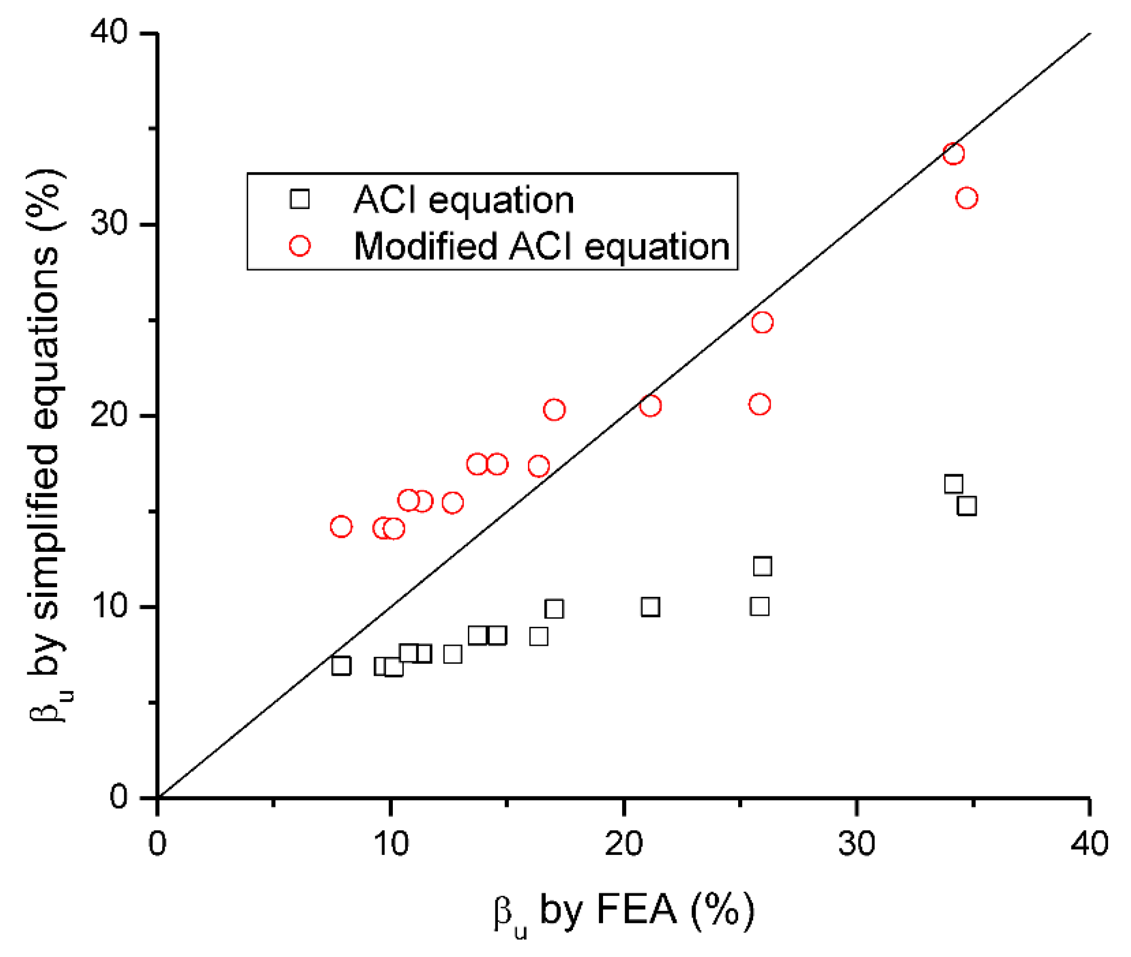
4. Evaluation of Simplified Equations for Predicting Moment Redistribution
5. Conclusions
- Using hybrid or CFRP bars can effectively mitigate the cracking concentration of beams. Increasing Af/Ar leads to a reduction in crack width in the critical section at ultimate.
- Increasing Af/Ar leads to a reduction in yielding load and moment. The ultimate load is enhanced by 16.0% at symmetrical loading and by 11.3% at unsymmetrical loading, when Af/Ar increases from 0.0 to 0.25. With continuing increases in Af/Ar, the enhancement of the ultimate load is rather limited.
- At symmetrical and unsymmetrical loading, beams with Af/Ar of 0.25 show 11.7% and 16.3% higher ultimate deflection than beams with Af/Ar of 0.0, respectively. As Af/Ar increases from 0.25 to 1.0, the change in ultimate deflection appears to be unimportant. Unsymmetrical loading leads to 6.0–15.0% higher ultimate deflection than symmetrical loading.
- A higher Af/Ar ratio leads to significantly lower moment redistribution at symmetrical loading. The redistribution value is decreased by 62% as Af/Ar increases from 0.0 to 1.0. By contrast, the influence of Af/Ar on moment redistribution appears to be marginal at unsymmetrical loading.
- The influence of Af/Ar and load type on moment redistribution is generally reflected in the ACI and modified ACI equations. The ACI equation shows conservative prediction on moment redistribution but appears to be over-conservative at a low Af/Ar. The modified ACI equation is much more accurate than the ACI equation for predicting moment redistribution in those beams.
Author Contributions
Funding
Institutional Review Board Statement
Informed Consent Statement
Data Availability Statement
Conflicts of Interest
References
- Nepomuceno, M.C.S.; Pereira-de-Oliveira, L.A.; Lopes, S.M.R. Methodology for the mix design of self-compacting concrete using different mineral additions in binary blends of powders. Constr. Build. Mater. 2014, 64, 82–94. [Google Scholar] [CrossRef]
- Miraldo, S.; Lopes, S.; Pacheco-Torgal, F.; Lopes, A. Advantages and shortcomings of the utilization of recycled wastes as aggregates in structural concretes. Constr. Build. Mater. 2021, 298, 123729. [Google Scholar] [CrossRef]
- Smirnova, O.; Kazanskaya, L.; Koplík, J.; Tan, H.; Gu, X. Concrete based on clinker-free cement: Selecting the functional unit for environmental assessment. Sustainability 2021, 13, 135. [Google Scholar] [CrossRef]
- Ahmad, S. Reinforcement corrosion in concrete structures, its monitoring and service life prediction—A review. Cem. Concr. Compos. 2003, 25, 459–471. [Google Scholar] [CrossRef]
- ACI Committee 440. ACI 440.1R-15; Guide for the Design and Construction of Structural Concrete Reinforced with FRP Bars. American Concrete Institute: Farmington Hills, MI, USA, 2015.
- Alkhraisha, H.; Mhanna, H.; Tello, N.; Abed, F. Serviceability and flexural behavior of concrete beams reinforced with basalt fiber-reinforced polymer (BFRP) bars exposed to harsh conditions. Polymers 2020, 12, 2110. [Google Scholar] [CrossRef]
- Pang, M.; Li, Z.; Lou, T. Numerical study of using FRP and steel rebars in simply supported prestressed concrete beams with external FRP tendons. Polymers 2020, 12, 2773. [Google Scholar] [CrossRef]
- Aksoylu, C.; Özkılıç, Y.O.; Arslan, M.H. Mechanical Steel Stitches: An innovative approach for strengthening shear deficiency in undamaged reinforced concrete beams. Buildings 2022, 12, 1501. [Google Scholar] [CrossRef]
- Wang, H.; Belarbi, A. Ductility characteristics of fiber-reinforced-concrete beams reinforced with FRP rebars. Constr. Build. Mater. 2011, 25, 2391–2401. [Google Scholar] [CrossRef]
- Oehlers, D.J.; Muhamad, R.; Mohamed Ali, M.S. Serviceability flexural ductility of FRP RC beams: A discrete rotation approach. Constr. Build. Mater. 2013, 49, 974–984. [Google Scholar] [CrossRef]
- Lou, T.; Lopes, S.M.R.; Lopes, A.V. Neutral axis depth and moment redistribution in FRP and steel reinforced concrete continuous beams. Compos. Part B Eng. 2015, 70, 44–52. [Google Scholar] [CrossRef]
- Pang, M.; Shi, S.; Hu, H.; Lou, T. Flexural behavior of two-span continuous CFRP RC beams. Materials 2021, 14, 6746. [Google Scholar] [CrossRef]
- Santos, P.; Laranja, G.; Franca, P.M.; Correia, J.R. Ductility and moment redistribution capacity of multi-span T-section concrete beams reinforced with GFRP bars. Constr. Build. Mater. 2013, 49, 949–961. [Google Scholar] [CrossRef]
- Basa, N.; Vukovic, N.K.; Ulicevic, M.; Muhadinovic, M. Effects of internal force redistribution on the limit states of continuous beams with GFRP reinforcement. Appl. Sci. 2020, 10, 3973. [Google Scholar] [CrossRef]
- Kara, I.F.; Ashour, A.F.; Dundar, C. Deflection of concrete structures reinforced with FRP bars. Compos. Part B Eng. 2013, 44, 375–384. [Google Scholar] [CrossRef] [Green Version]
- Al-Sunna, R.; Pilakoutas, K.; Hajirasouliha, I.; Guadagnini, M. Deflection behaviour of FRP reinforced concrete beams and slabs: An experimental investigation. Compos. Part B Eng. 2012, 43, 2125–2134. [Google Scholar] [CrossRef]
- Dundar, C.; Tanrikulu, A.K.; Frosch, R.J. Prediction of load-deflection behavior of multi-span FRP and steel reinforced concrete beams. Compos. Struct. 2015, 132, 680–693. [Google Scholar] [CrossRef]
- Ju, M.; Park, Y.; Park, C. Cracking control comparison in the specifications of serviceability in cracking for FRP reinforced concrete beams. Compos. Struct. 2018, 182, 674–684. [Google Scholar] [CrossRef]
- Barris, C.; Torres, L.; Vilanova, I.; Mias, C.; Llorens, M. Experimental study on crack width and crack spacing for Glass-FRP reinforced concrete beams. Eng. Struct. 2017, 131, 231–242. [Google Scholar] [CrossRef]
- Karayannis, C.G.; Kosmidou, P.M.K.; Chalioris, C.E. Reinforced concrete beams with carbon-fiber-reinforced polymer bars—Experimental study. Fibers 2018, 6, 99. [Google Scholar] [CrossRef] [Green Version]
- Ge, W.; Song, W.; Ashour, A.F.; Lu, W.; Cao, D. Flexural performance of FRP/steel hybrid reinforced engineered cementitious composite beams. J. Build. Eng. 2020, 31, 101329. [Google Scholar] [CrossRef]
- Zhou, B.; Wu, R.; Lu, S.; Yin, S. A general numerical model for predicting the flexural behavior of hybrid FRP-steel reinforced concrete beams. Eng. Struct. 2021, 239, 112293. [Google Scholar] [CrossRef]
- Wang, X.; Chen, Z.; Ding, L.; Shi, Y.; Zhu, Z.; Wu, Z. Long-term flexural behavior of concrete beams with hybrid FRP and steel reinforcements in simulated marine environment. Structures 2021, 33, 4556–4567. [Google Scholar] [CrossRef]
- Moolaei, S.; Sharbatdar, M.K.; Kheyroddin, A. Experimental evaluation of flexural behavior of HPFRCC beams reinforced with hybrid steel and GFRP bars. Compos. Struct. 2021, 275, 114503. [Google Scholar] [CrossRef]
- Yang, Y.; Pan, D.; Wu, G.; Cao, D. A new design method of the equivalent stress–strain relationship for hybrid (FRP bar and steel bar) reinforced concrete beams. Compos. Struct. 2021, 270, 114099. [Google Scholar] [CrossRef]
- Thamrin, R.; Zaidir, Z.; Iwanda, D. Ductility estimation for flexural concrete beams longitudinally reinforced with hybrid FRP–steel bars. Polymers 2022, 14, 1017. [Google Scholar] [CrossRef]
- Gemi, L.; Madenci, E.; Özkılıç, Y.O.; Yazman, Ş.; Safonov, A. Effect of fiber wrapping on bending behavior of reinforced concrete filled pultruded GFRP composite hybrid beams. Polymers 2022, 14, 3740. [Google Scholar] [CrossRef] [PubMed]
- Gemi, L.; Madenci, E.; Özkılıç, Y.O. Experimental, analytical and numerical investigation of pultruded GFRP composite beams infilled with hybrid FRP reinforced concrete. Eng. Struct. 2021, 244, 112790. [Google Scholar] [CrossRef]
- Araba, A.M.; Ashour, A.F. Flexural performance of hybrid GFRP-Steel reinforced concrete continuous beams. Compos. Part B 2018, 154, 321–336. [Google Scholar] [CrossRef] [Green Version]
- Almahmood, H.; Ashour, A.; Sheehan, T. Flexural behaviour of hybrid steel-GFRP reinforced concrete continuous T-beams. Compos. Struct. 2020, 254, 112802. [Google Scholar] [CrossRef]
- Akiel, M.; El-Maaddawy, T.; El Refai, A. Serviceability and moment redistribution of continuous concrete members reinforced with hybrid steel-BFRP bars. Constr. Build. Mater. 2018, 175, 672–681. [Google Scholar] [CrossRef]
- EN 1992-1-1; Eurocode 2: Design of Concrete Structures—Part 1-1: General Rules and Rules for Buildings. European Committee for Standardization: Brussels, Belgium, 2004.
- Lou, T.; Lopes, S.M.R.; Lopes, A.V. FE modeling of inelastic behavior of reinforced high-strength concrete continuous beams. Struct. Eng. Mech. 2014, 49, 373–393. [Google Scholar] [CrossRef]
- Lou, T.; Lopes, S.M.R.; Lopes, A.V. Redistribution of moments in reinforced high-strength concrete beams with and without confinement. Struct. Eng. Mech. 2015, 55, 379–398. [Google Scholar] [CrossRef]
- ACI 318-19; Building Code Requirements for Structural Concrete (ACI 318-19) and Commentary (ACI 318R-19). American Concrete Institute: Farmington Hills, MI, USA, 2019.
- Lou, T.; Lopes, S.M.R.; Lopes, A.V. Effect of relative stiffness on moment redistribution in reinforced high-strength concrete beams. Mag. Concr. Res. 2017, 69, 716–727. [Google Scholar] [CrossRef]


| Load Pattern | Af/Ar | Me (kN·m) | Mu (kN·m) | βu (%) | |||
|---|---|---|---|---|---|---|---|
| Midspan | Support | Midspan | Support | Midspan | Support | ||
| Sym. | 0.0 | 749.6 | −868.8 | 862.4 | −643.3 | −15.04 | 25.96 |
| 0.25 | 867.3 | −1006.1 | 953.0 | −834.7 | −9.88 | 17.04 | |
| 0.5 | 920.5 | −1069.7 | 993.9 | −922.8 | −7.98 | 13.73 | |
| 0.75 | 936.3 | −1090.5 | 998.3 | −966.5 | −6.62 | 11.37 | |
| 1.0 | 935.3 | −1092.0 | 988.3 | −985.9 | −5.67 | 9.71 | |
| Unsym. | 0.0 | 838.8 | −643.7 | 863.4 | −594.6 | −2.93 | 7.63 |
| 0.25 | 931.9 | −715.2 | 964.5 | −649.9 | −3.50 | 9.13 | |
| 0.5 | 955.0 | −734.1 | 989.2 | −665.8 | −3.57 | 9.30 | |
| 0.75 | 968.9 | −746.1 | 1003.1 | −677.8 | −3.53 | 9.16 | |
| 1.0 | 973.9 | −751.5 | 1008.2 | −682.8 | −3.52 | 9.13 | |
| Load Type | Af/Ar | Mu (kN·m) | Me (kN·m) | εt (%) | βu (%) | ||
|---|---|---|---|---|---|---|---|
| FEA | ACI | Modified ACI | |||||
| Center-point | 0.0 | −643.3 | −868.8 | 1.21 | 25.96 | 12.13 | 24.86 |
| 0.25 | −834.7 | −1006.1 | 0.99 | 17.04 | 9.91 | 20.31 | |
| 0.5 | −922.8 | −1069.7 | 0.85 | 13.73 | 8.52 | 17.47 | |
| 0.75 | −966.5 | −1090.5 | 0.76 | 11.37 | 7.58 | 15.53 | |
| 1.0 | −985.9 | −1092.0 | 0.69 | 9.71 | 6.89 | 14.13 | |
| Third-point | 0.0 | −673.5 | −1031.8 | 1.53 | 34.72 | 15.30 | 31.36 |
| 0.25 | −855.0 | −1084.4 | 1.00 | 21.15 | 10.02 | 20.53 | |
| 0.5 | −934.4 | −1117.2 | 0.85 | 16.37 | 8.47 | 17.37 | |
| 0.75 | −975.8 | −1117.4 | 0.75 | 12.67 | 7.54 | 15.45 | |
| 1.0 | −996.1 | −1108.7 | 0.69 | 10.15 | 6.88 | 14.10 | |
| Uniform | 0.0 | −702.5 | −1067.2 | 1.64 | 34.17 | 16.43 | 33.68 |
| 0.25 | −881.7 | −1189.2 | 1.00 | 25.86 | 10.05 | 20.59 | |
| 0.5 | −962.7 | −1126.9 | 0.85 | 14.58 | 8.52 | 17.46 | |
| 0.75 | −1007.0 | −1128.6 | 0.76 | 10.78 | 7.60 | 15.58 | |
| 1.0 | −1025.9 | −1114.0 | 0.69 | 7.91 | 6.92 | 14.19 | |
Publisher’s Note: MDPI stays neutral with regard to jurisdictional claims in published maps and institutional affiliations. |
© 2022 by the authors. Licensee MDPI, Basel, Switzerland. This article is an open access article distributed under the terms and conditions of the Creative Commons Attribution (CC BY) license (https://creativecommons.org/licenses/by/4.0/).
Share and Cite
Pang, M.; Dong, Y.; Liu, X.; Sun, W.; Lou, T. Prediction of Structural Behavior of Continuous Reinforced Concrete Beams with Hybrid CFRP-Steel Bars. Materials 2022, 15, 7542. https://doi.org/10.3390/ma15217542
Pang M, Dong Y, Liu X, Sun W, Lou T. Prediction of Structural Behavior of Continuous Reinforced Concrete Beams with Hybrid CFRP-Steel Bars. Materials. 2022; 15(21):7542. https://doi.org/10.3390/ma15217542
Chicago/Turabian StylePang, Miao, Yi Dong, Xing Liu, Wei Sun, and Tiejiong Lou. 2022. "Prediction of Structural Behavior of Continuous Reinforced Concrete Beams with Hybrid CFRP-Steel Bars" Materials 15, no. 21: 7542. https://doi.org/10.3390/ma15217542