
Testing and Evaluation of Flexural Tensile Strength of Prestressed CFRP Cables


Abstract
:1. Introduction
2. Theoretical Research
2.1. Failure Mechanism
2.2. Tensile Strength of CFRP Tendons
2.3. Tensile Strength of CFRP Cables
3. Experimental Study
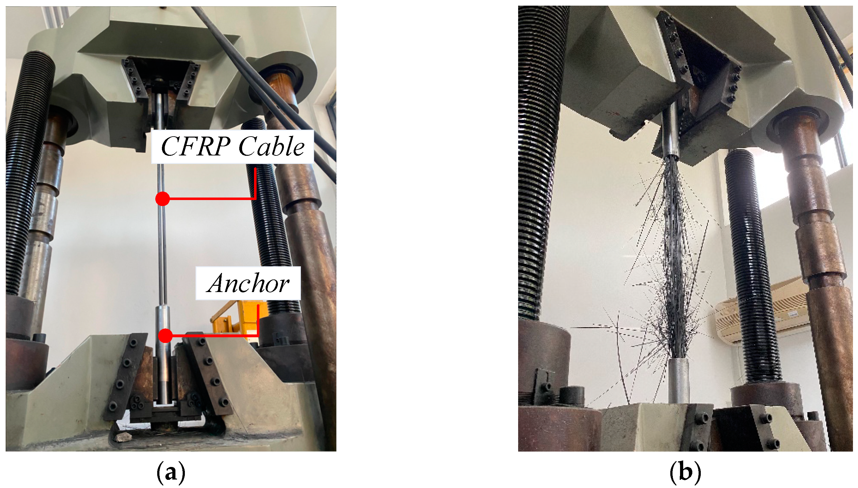
3.1. Tensile Strength Test of CFRP Cables
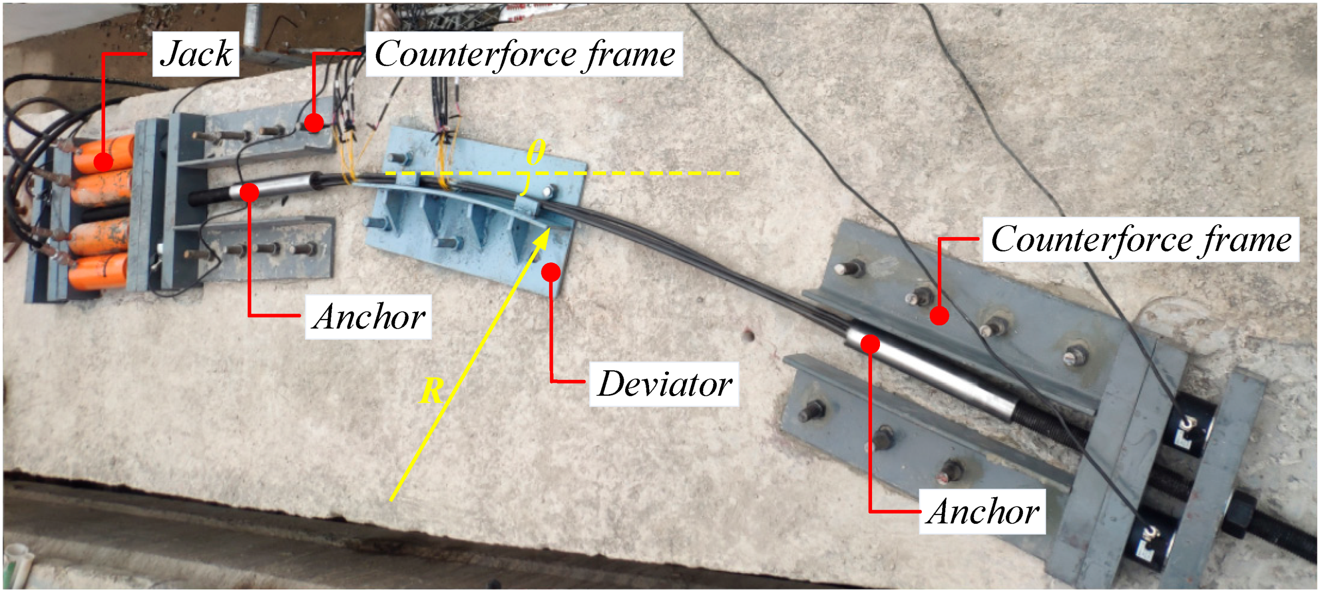
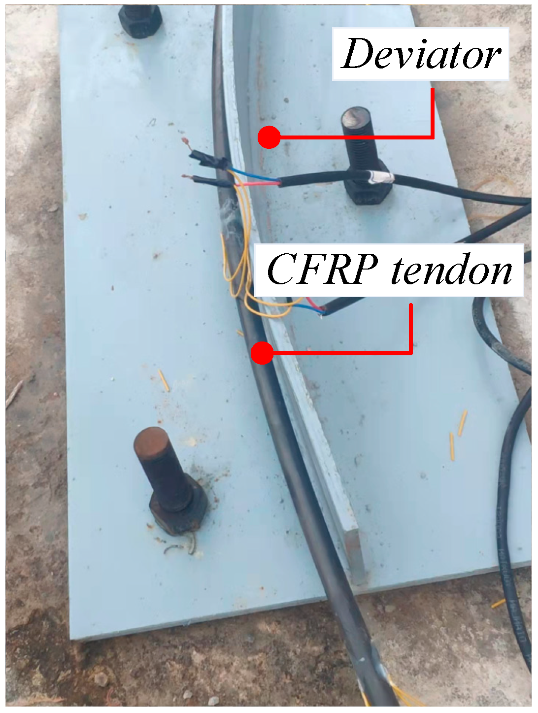
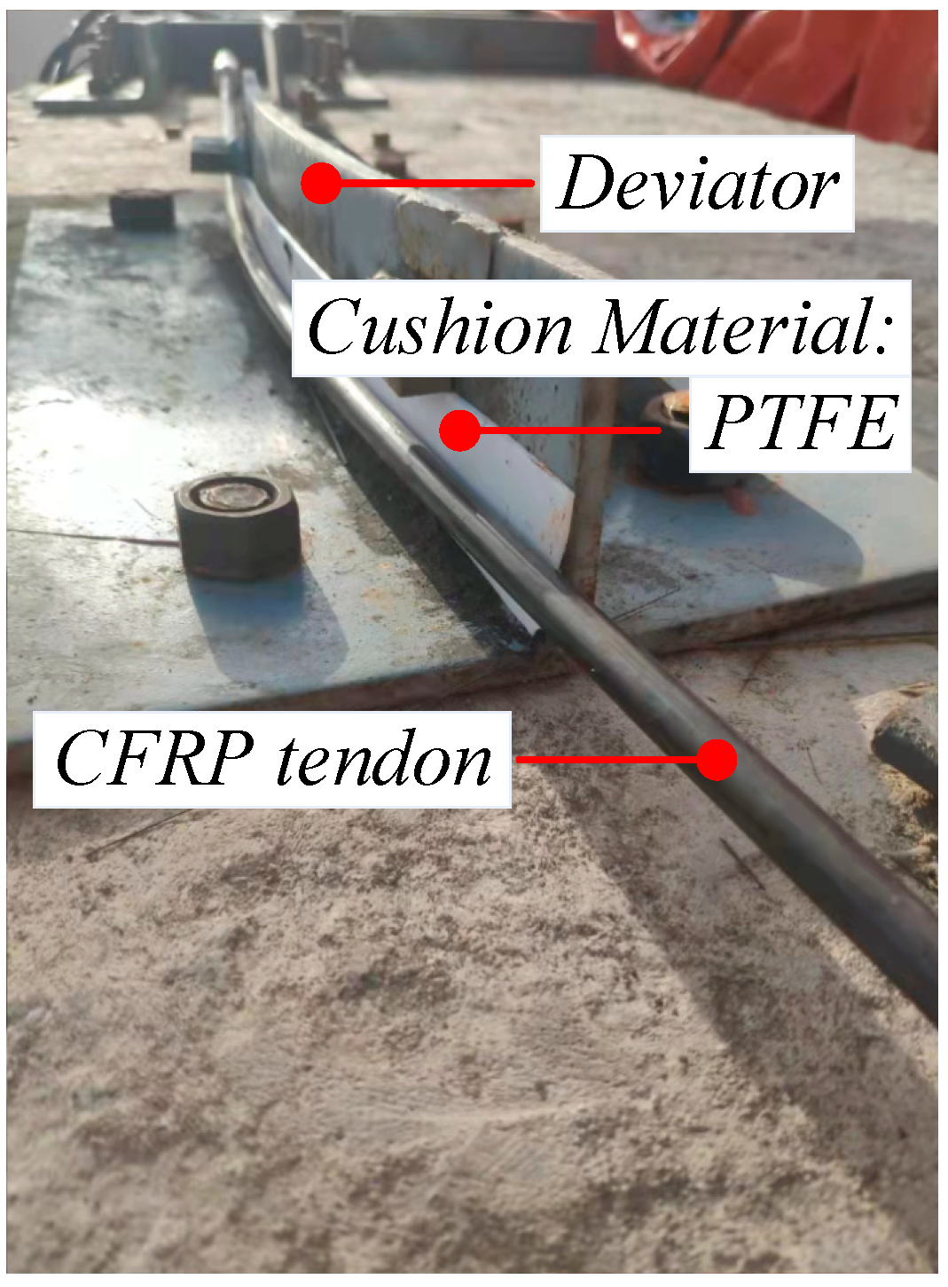
3.2. Tensile Strength Test of CFRP Cable under Bending
3.2.1. Test Scheme
3.2.2. Test Results
3.2.3. Test Verification
4. Discussion and Prediction
4.1. Discussion
4.2. Prediction
5. Conclusions
Author Contributions
Funding
Institutional Review Board Statement
Informed Consent Statement
Data Availability Statement
Conflicts of Interest
References
- Zhang, Y.; Li, Y.; Zhang, J.; Pan, J.; Zhang, L.; Tan, F.; Wei, H.; Zhang, W. High-Temperature Effect on the Tensile Mechanical Properties of Unidirectional Carbon Fiber-Reinforced Polymer Plates. Materials 2021, 14, 7214. [Google Scholar] [CrossRef]
- Chawla, K.K. Carbon fiber/carbon matrix composites. In Composite Materials; Springer: Berlin/Heidelberg, Germany, 2019; pp. 297–311. [Google Scholar]
- Hammerl, M.; Kromoser, B. Bending Behaviour of Prestressed T-Shaped Concrete Beams Reinforced with FRP—Experimental and Analytical Investigations. Materials 2022, 15, 3843. [Google Scholar] [CrossRef] [PubMed]
- Masuelli, M.A. Introduction of Fibre-Reinforced Polymers−Polymers and Composites: Concepts, Properties and Processes; INTECH Open Access Publisher: Rijeka, Croatia, 2013. [Google Scholar]
- Meier, U. Carbon Fiber Reinforced Polymer Cables: Why? Why Not? What If? Arab. J. Sci. Eng. 2012, 37, 399–411. [Google Scholar] [CrossRef] [Green Version]
- Hollaway, L.C. Fibre-reinforced polymer (FRP) composites used in rehabilitation. In Strengthening and Rehabilitation of Civil Infrastructures Using Fibre-Reinforced Polymer (FRP) Composites; Hollaway, L.C., Teng, J.G., Eds.; Woodhead Publishing: Sawston, UK, 2008; pp. 45–82. [Google Scholar]
- Yang, Y.; Wang, X.; Wu, Z.; Peng, C. Damping properties of FRP cables for long-span cable-stayed bridges. Mater. Struct. 2015, 49, 2701–2713. [Google Scholar] [CrossRef]
- Feng, P.; Zhang, P.; Meng, X.; Ye, L. Mechanical Analysis of Stress Distribution in a Carbon Fiber-Reinforced Polymer Rod Bonding Anchor. Polymers 2014, 6, 1129–1143. [Google Scholar] [CrossRef] [Green Version]
- Grace, N.F.; Navarre, F.C.; Nacey, R.B.; Bonus, W.; Collavino, L.J.P.J. Design-Construction of Bridge Street Bridge—First CFRP Bridge in the United States. PCI J. 2002, 47, 20–35. [Google Scholar] [CrossRef]
- Karbhari, V.M. Use of Composite Materials in Civil Infrastructure in Japan; International Technology Research Institute: Baltimore, MD, USA, 1998; p. 211. [Google Scholar]
- ACI 440.4R-04; Prestressing Concrete Structures with FRP Tendons (Reapproved). American Concrete Institute: Farmington Hills, MI, USA, 2011.
- Rogowski, J.; Kotynia, R. Comparison of Prestressing Methods with CFRP and SMA Materials in Flexurally Strengthened RC Members. Materials 2022, 15, 1231. [Google Scholar] [CrossRef]
- Pang, M.; Li, Z.; Lou, T.J.P. Numerical study of using FRP and steel rebars in simply supported prestressed concrete beams with external FRP tendons. Polymers 2020, 12, 2773. [Google Scholar] [CrossRef]
- Jumaat, M.Z.; Rahman, M.; Alam, M.A. Flexural strengthening of RC continuous T beam using CFRP laminate: A review. Int. J. Phys. Sci. 2010, 5, 619–625. [Google Scholar]
- Sun, Y.; Huang, P.; Mei, K.; Wang, T. Vehicle-induced response of long-span suspension bridges with steel and carbon fiber-reinforced polymer (CFRP) cables and suspenders. Sci. Adv. Mater. 2018, 10, 913–922. [Google Scholar] [CrossRef]
- Nil Arın, A.; Süleyman, A.; Murat, G.; Ahmet Can, A.; Barış, S. Dynamic Analysis of a Suspension Bridge Using CFRP Composite Material. In Proceedings of the 2nd International Balkans Conference on Challenges of Civil Engineering, BCCCE, Tirana, Albania, 23–25 May 2013. [Google Scholar]
- Li, Y. Calculating Method for Cable Clips of Suspension Bridges with CFRP Cables. China J. Highw. Transp. 2015, 28, 67. [Google Scholar]
- CAN/CSA-S806-12; Design and Construction of Building Components with Fibre-Reinforced Polymers. Canadian Standards Association: Toronto, ON, Canada, 2012; p. 206.
- AASHTO; Standard Specifications for Highway Bridges, LRFD. US Customary Units, sixth Edition. American Association of State Highway andTransportation Officials: Washington, DC, USA, 2014.
- Belarbi, A.; Dawood, M.; Poudel, P.; Reda, M.; Tahsiri, H.; Gencturk, B.; Rizkalla, S.H.; Russell, H.G. Design of Concrete Bridge Beams Prestressed with CFRP Systems; Transportation Research Board: Washington, DC, USA, 2019. [Google Scholar]
- Fang, Y.; Fang, Z.; Jiang, R.; Jiang, Z.; Zhu, D. Effect of temperature on the transverse impact performance of preloaded CFRP wire. Compos. Struct. 2020, 231, 111464. [Google Scholar] [CrossRef]
- Yu, X.; Zhi, F.; Changlin, W. Experimental study on impact behaviors of CFRP cable and its anchoring system. China Civ. Eng. J. 2015, 48, 82–90. [Google Scholar]
- Zhuge, P.; Jie, Z.Y.; Zhang, Z.H.; Ding, Y.; Hou, S.W.J.C.; Materials, B. The influence of load transfer medium creep on the load-carrying capacity of the bond-type anchors of CFRP tendons. Constr. Build. Mater. 2019, 206, 236–247. [Google Scholar] [CrossRef]
- Jerrett, C.; Ahmad, S.; Scotti, G. Behavior of Carbon Fiber Reinforced Plastic (CRFP) Rods under Combined Axial and Flexural Loads. In Proceedings of the First International Conference on Composites in Infrastructure National Science FoundationNational Sicence Foundation, Tucson, AZ, USA, 15–17 January 1996. [Google Scholar]
- Hollaway, L.C.; Teng, J.G. Strengthening and Rehabilitation of Civil Infrastructures Using Fibre-Reinforced Polymer (FRP) Composites||Case Studies; Elsevier: Amsterdam, The Netherlands, 2008; pp. 352–385. [Google Scholar]
- Jiang, T. Experimental and Theoretical Investigation on the Anchorage System for CFRP Tendons. Ph.D. Thesis, Hu Nan University, Changsha, China, 2008. [Google Scholar]
- Xu, J.; Wang, W.; Han, Q.; Liu, X.J.C.S. Damage pattern recognition and damage evolution analysis of unidirectional CFRP tendons under tensile loading using acoustic emission technology. Compos. Struct. 2020, 238, 111948. [Google Scholar] [CrossRef]
- Cai, D.-S.; Yin, J.; Liu, R.-G. Experimental and analytical investigation into the stress performance of composite anchors for CFRP tendons. Compos. Part B Eng. 2015, 79, 530–534. [Google Scholar] [CrossRef]
- Noisternig, J.F.J.A.C.M. Carbon fibre composites as stay cables for bridges. Appl. Compos. Mater. 2000, 7, 139–150. [Google Scholar] [CrossRef]
- Adachi, Y.; Hayashida, M.; Sakai, H.; Mashima, M.; Miyagawa, T. Strengthening of Prestressed Concrete Segmental T-Beam Bridge Using FRP External Prestressing Systems. In Proceedings of the Non-Metallic (FRP) Reinforcement for Concrete Structures, Sapporo, Japan, 14–16 October 1997; pp. 695–702. [Google Scholar]
- Van Jerrett, C. Performance of Carbon Fiber Reinforced Polymer (CFRP) Tendons and Their Use for Strengthening of Prestressed Concrete Beams (No. 97-007D); Department of Civil Engineering, North Carolina State University at Raleigh: Raleigh, NC, USA, 1996. [Google Scholar]
- ACI 440.1R-06; Guide for the Design and Construction of Structural Concrete Reinforced with Fiber-Reinforced Polymer (FRP) Bars. American Concrete Institute: Farmington Hills, MI, USA, 2015.
- ASTM D790-07; Standard test methods for flexural properties of unreinforced and reinforced plastics and electrical insulating materials. American Society for Testing and Materials: Conshohocken, PA, USA, 2007.
- ASTM D4476/D4476M-14; Standard test method for flexural properties of fiber reinforced pultruded plastic rods. American Society for Testing and Materials: Conshohocken, PA, USA, 2009.
- El-Sayed, A.K.; El-Salakawy, E.; Benmokrane, B.J. Mechanical and Structural Characterization of New Carbon FRP Stirrups for Concrete Members. J. Compos. Constr. 2007, 11, 352–362. [Google Scholar] [CrossRef]
- Menezes, E.; Silva, L.V.d.; Junior, C.A.C.; Luz, F.F.; Amico, S.C.J.P.; Composites, P. Numerical and Experimental Analysis of the Tensile and Bending Behaviour of CFRP Cables. Polym. Polym. Compos. 2017, 25, 643–650. [Google Scholar] [CrossRef]
- Zhuge, P.; Qiang, S.-Z.; Hou, S.-W.; Liu, M.-H. Transport. Research on bending performance of CFRP main cable in saddle of suspension bridge. China J. Highw. Transp. 2011, 24, 57. [Google Scholar]
- Zhang, B.; Masmoudi, R.; Benmokrane, B. New Method for Testing Fiber-reinforced Polymer Rods Under Flexure. J. Test. Eval. 2006, 35, 171–176. [Google Scholar] [CrossRef]
- ACI-440.3R-04; Guide Test Methods For Fiber-Reinforced Polymers (Frps) For Reinforcing Or Strengthening Concrete Structures. American Concrete Institute: Farmington Hills, MI, USA, 2004.
- JSCE-E 531-1995; Test Method for Tensile Properties of Continuous Fiber Reinforcing Materials. Japan Society of Civil Engineers: Tokyo, Japan, 1995.
- Liu, Y.; Zwingmann, B.; Schlaich, M. Carbon fiber reinforced polymer for cable structures—A review. Polymers 2015, 7, 2078–2099. [Google Scholar] [CrossRef] [Green Version]
- Meier, U. Structural tensile elements made of advanced composite materials. Struct. Eng. Int. 1999, 9, 281–285. [Google Scholar] [CrossRef]
- Rohleder, W.J.; Tang, B.; Doe, T.A. Carbon fiber-reinforced polymer strand application on cable-stayed bridge, Penobscot narrows, Maine. Transp. Res. Rec. 2008, 2050, 169–176. [Google Scholar] [CrossRef]
- AASHTO; Guide Specification for the Design of Concrete Bridge Beams Prestressed with CFRP Systems. US Customary Units, sixth Edition. American Association of State Highway and Transportation Officials: Washington, DC, USA, 2017.
- ACI 440.2R-02; Guide for the design and construction of externally bonded FRP systems for strengthening existing structures. American Concrete Institute: Farmington Hills, MI, USA, 2014; pp. 1–8.


| Bending Angles/m | n | a | Failure Mode |
|---|---|---|---|
| 0.7 (Critical Radius) | ≤5550 | ≤87 | 1 |
| ≥5550 | ≥87 | 2 | |
| 1 | ≤16,500 | ≤149 | 1 |
| ≥16,500 | ≥149 | 2 | |
| 1.5 | ≤92,800 | ≤352 | 1 |
| ≥92,800 | ≥352 | 2 | |
| 2 | ≤272,400 | ≤603 | 1 |
| ≥272,400 | ≥603 | 2 |
| Test Conditions | Specification/mm | UBC F /kN | Average Value of UBC
/kN |
|---|---|---|---|
| S-1 | 3 × 10 | 494.6 | 492.1 |
| S-2 | 3 × 10 | 513.9 | |
| S-3 | 3 × 10 | 467.7 |
| Test Conditions | Bending Radii R /m | Bending Angles θ /° | Cushion Material | Specification /mm |
|---|---|---|---|---|
| BF-20 | 1.5 | 20 | / | 1 × 10 |
| B-20 | PTFE | 1 × 10 | ||
| BF-30 | 30 | / | 1 × 10 | |
| B-30 | PTFE | 1 × 10 | ||
| BF-40 | 40 | / | 1 × 10 | |
| B-40 | PTFE | 1 × 10 |
| Test Conditions | Bending Radii R /m | Bending Angles θ /° | Cushion Material | Specification /mm |
|---|---|---|---|---|
| BF-R1.5-A | 1.5 | 20 | / | 3 × 10 |
| BF-R1.5-B | 3 × 10 | |||
| BF-R2-A | 2 | 3 × 10 | ||
| BF-R2-B | 3 × 10 | |||
| BF-R2.5-A | 2.5 | 3 × 10 | ||
| BF-R2.5-B | 3 × 10 | |||
| BF-R3-A | 3 | 3 × 10 | ||
| BF-R3-B | 3 × 10 |
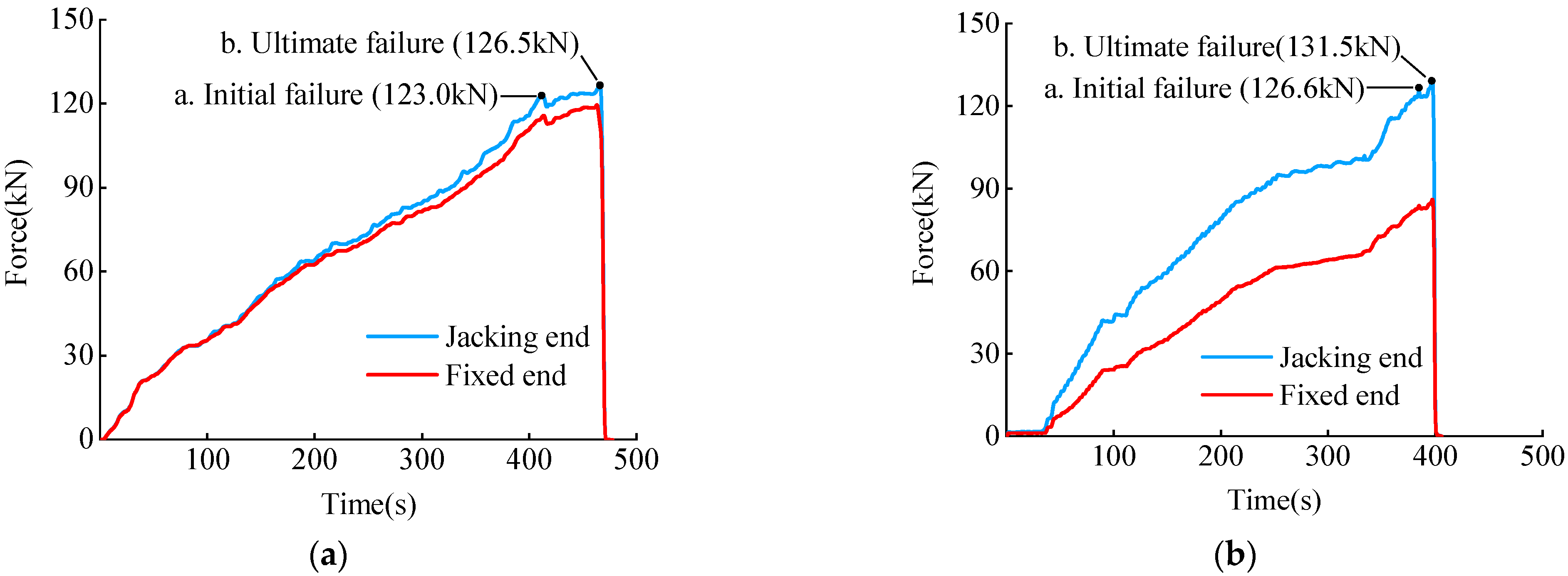
| Test Conditions | Test Value /kN | Theoretical Value /kN | Test Value and Theoretical Value Ratio /% |
|---|---|---|---|
| BF-20 | 131.5 | 131.3 | 1.002 |
| B-20 | 126.5 | 0.963 | |
| BF-30 | 132.8 | 1.011 | |
| B-30 | 125.5 | 0.956 | |
| BF-40 | 129.1 | 0.983 | |
| BF-40 | 131.8 | 1.004 | |
| BF-R1.5-A | 360.6 | 393.9 | 0.915 |
| BF-R1.5-B | 326.2 | 0.828 | |
| BF-R2-A | 401.4 | 424.5 | 0.946 |
| BF-R2-B | 411.6 | 0.970 | |
| BF-R2.5-A | 445.2 | 443.1 | 1.005 |
| BF-R2.5-B | 435.9 | 0.984 | |
| BF-R3-A | 457.7 | 455.7 | 1.004 |
| BF-R3-B | 460.7 | 1.011 |
| Test Conditions | (%) | (%) | (%) |
|---|---|---|---|
| BF-20 | 76.10 | 74.65 | 75.98 |
| B-20 | 73.21 | ||
| BF-30 | 76.85 | 74.74 | |
| B-30 | 72.63 | ||
| BF-40 | 74.71 | 75.49 | |
| BF-40 | 76.27 | ||
| BF-R1.5-A | 69.57 | 69.57 | 75.99 |
| BF-R1.5-B | 62.93 | ||
| BF-R2-A | 77.44 | 78.42 | 81.89 |
| BF-R2-B | 79.40 | ||
| BF-R2.5-A | 85.89 | 84.99 | 85.48 |
| BF-R2.5-B | 84.09 | ||
| BF-R3-A | 88.30 | 88.59 | 87.91 |
| BF-R3-B | 88.88 |
Publisher’s Note: MDPI stays neutral with regard to jurisdictional claims in published maps and institutional affiliations. |
© 2022 by the authors. Licensee MDPI, Basel, Switzerland. This article is an open access article distributed under the terms and conditions of the Creative Commons Attribution (CC BY) license (https://creativecommons.org/licenses/by/4.0/).
Share and Cite
Xia, J.; Xu, Z.; Zhuge, P.; Wang, B.; Cai, W.; Fu, J. Testing and Evaluation of Flexural Tensile Strength of Prestressed CFRP Cables. Materials 2022, 15, 7065. https://doi.org/10.3390/ma15207065
Xia J, Xu Z, Zhuge P, Wang B, Cai W, Fu J. Testing and Evaluation of Flexural Tensile Strength of Prestressed CFRP Cables. Materials. 2022; 15(20):7065. https://doi.org/10.3390/ma15207065
Chicago/Turabian StyleXia, Jiajun, Zhirong Xu, Ping Zhuge, Bing Wang, Wanyun Cai, and Jiaping Fu. 2022. "Testing and Evaluation of Flexural Tensile Strength of Prestressed CFRP Cables" Materials 15, no. 20: 7065. https://doi.org/10.3390/ma15207065