
Injection Molding and Sintering of ZrO2 Ceramic Powder Modified by a Zirconate Coupling Agent
 , and
, and
Abstract
:1. Introduction
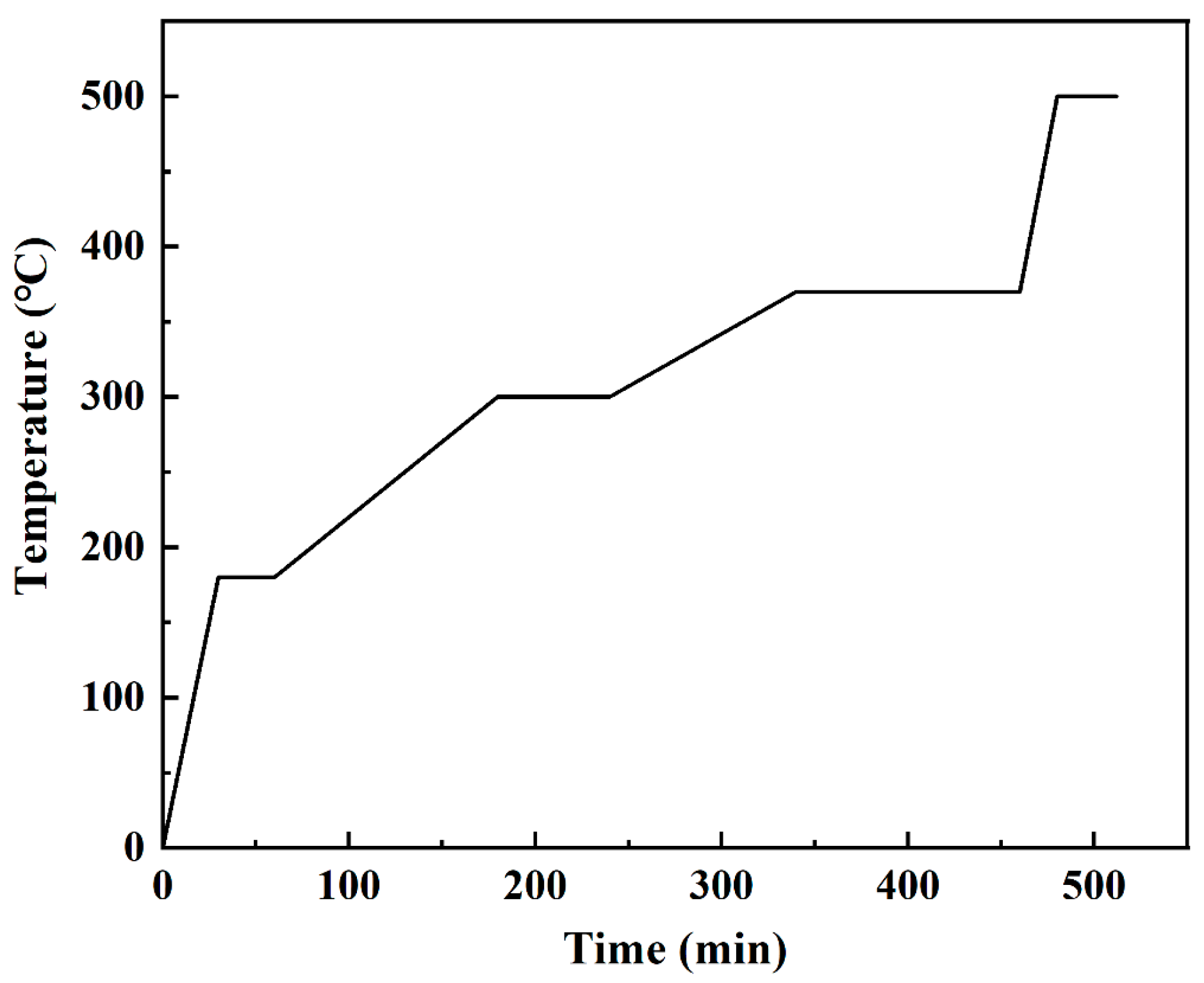
2. Experimental
3. Results and Discussion
3.1. Effect of Coupling Media
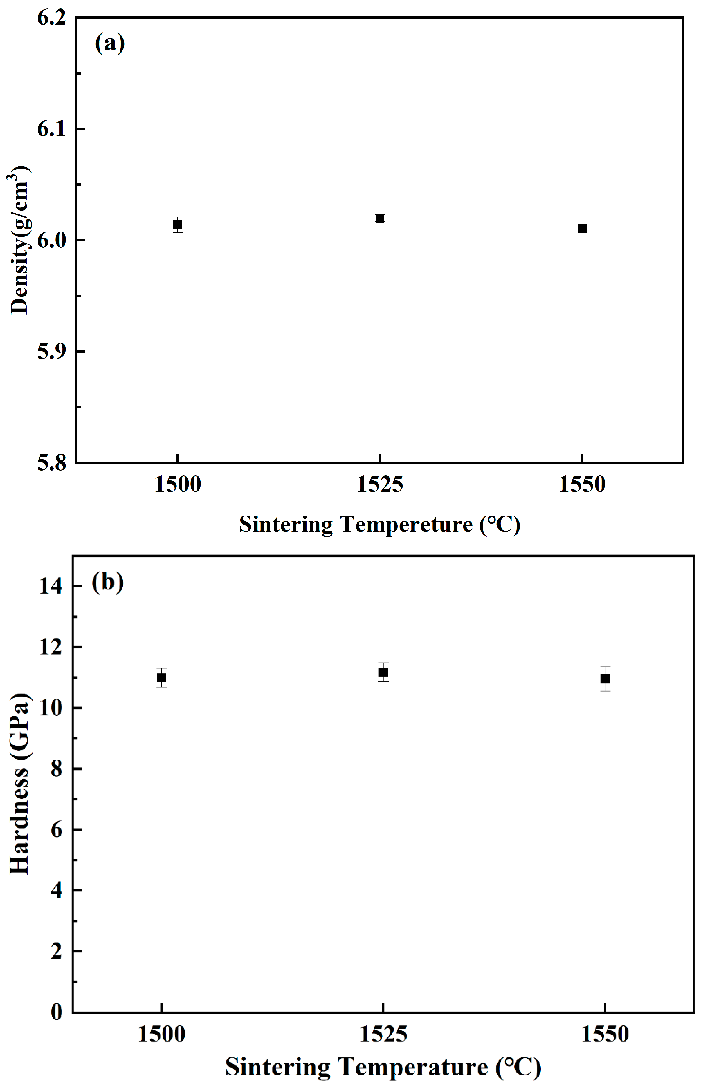
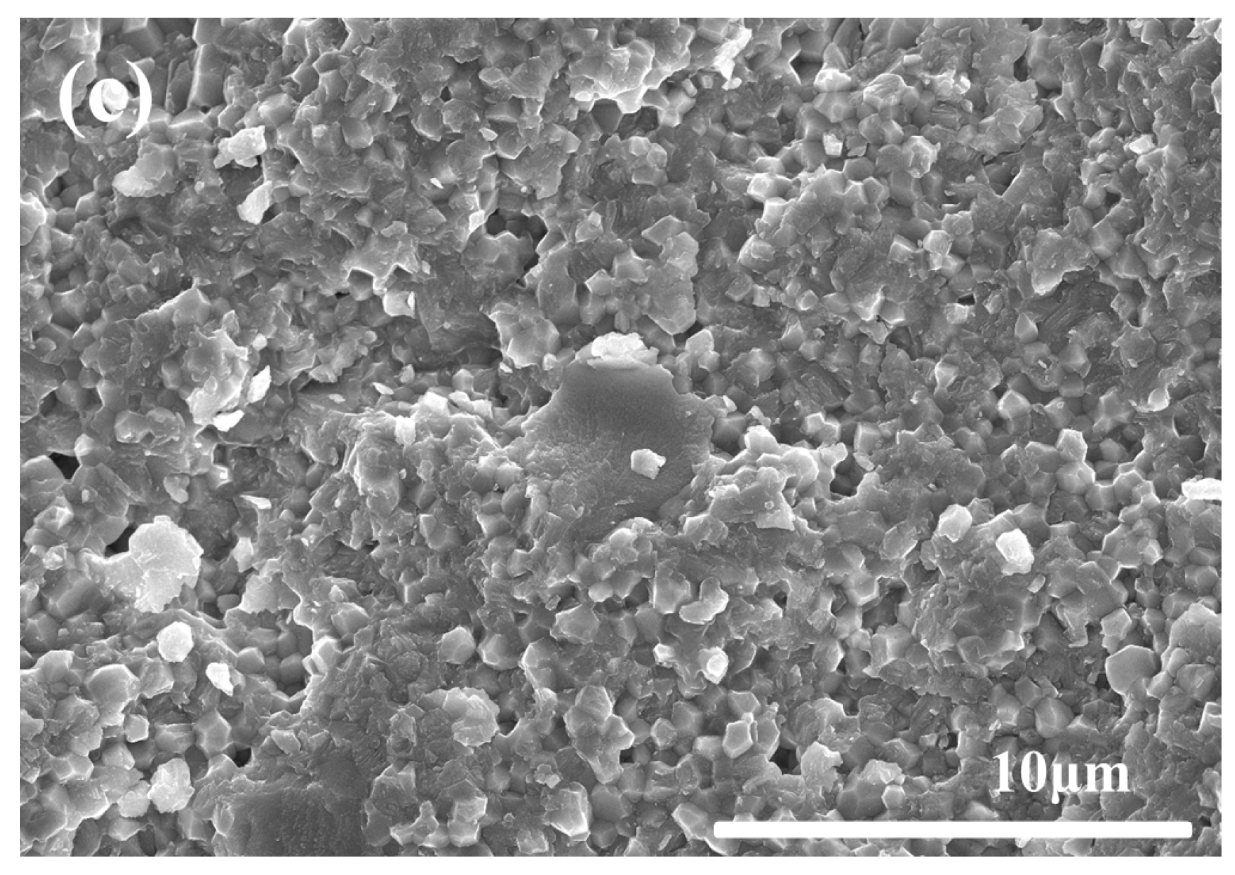
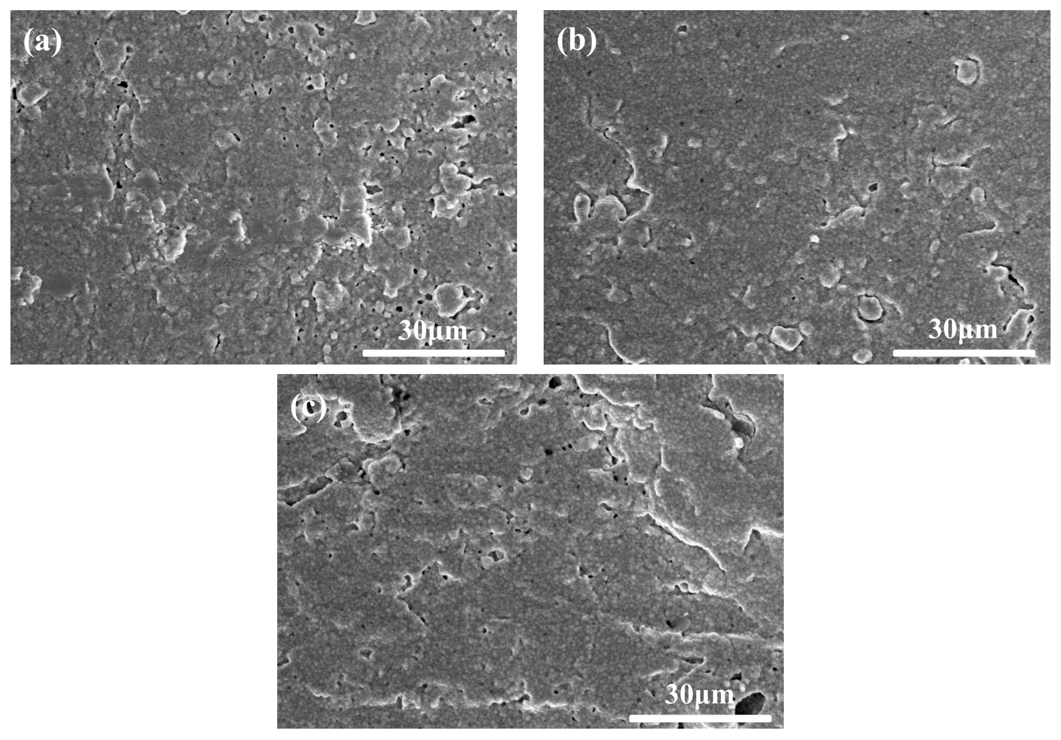
3.2. Effect of Sintering Temperature
4. Conclusions
Author Contributions
Funding
Institutional Review Board Statement
Informed Consent Statement
Data Availability Statement
Conflicts of Interest
References
- Chevalier, J.; Liens, A.; Reveron, H.; Zhang, F.; Reynaud, P.; Douillard, T.; Preiss, L.; Sergo, V.; Lughi, V.; Swain, M.; et al. Forty years after the promise of <<ceramic steel?>>: Zirconia-based composites with a metal-like mechanical behavior. J. Am. Ceram. Soc. 2020, 103, 1482–1513. [Google Scholar] [CrossRef]
- Kelly, J.R.; Denry, I. Stabilized zirconia as a structural ceramic: An overview. Dent. Mater. 2008, 24, 289–298. [Google Scholar] [CrossRef] [PubMed]
- Trunec, M.; Chlup, Z. Higher fracture toughness of tetragonal zirconia ceramics through nanocrystalline structure. Scr. Mater. 2009, 61, 56–59. [Google Scholar] [CrossRef]
- Sun, Q.Y.; Liu, T.; Wen, T.P.; Yu, J.K. Optimization of particle size, dispersity, and conductivity of 8 mol% Y2O3 doped tetragonal zirconia polycrystalline nanopowder prepared by modified sol-gel method via activated carbon absorption. J. Eur. Ceram. Soc. 2022, 42, 5831–5841. [Google Scholar] [CrossRef]
- Alves, M.F.R.P.; Abreu, L.G.; Klippel, G.G.P.; Santos, C.; Strecker, K. Mechanical properties and translucency of a multi-layered zirconia with color gradient for dental applications. Ceram. Int. 2021, 47, 301–309. [Google Scholar] [CrossRef]
- Daou, E.E. The zirconia ceramic: Strengths and weaknesses. Open Dent. J. 2014, 8, 33–42. [Google Scholar] [CrossRef]
- Nakonieczny, D.S.; Kern, F.; Dufner, L.; Antonowicz, M.; Matus, K. Alumina and Zirconia-Reinforced Polyamide PA-12 Composites for Biomedical Additive Manufacturing. Materials 2021, 14, 6201. [Google Scholar] [CrossRef]
- Taruta, S.; Yamaguchi, I.; Yamakami, T.; Yamaguchi, T. Sintering behavior and mechanical properties of machinable zirconia/mica composites. J. Asian Ceram. Soc. 2019, 7, 342–349. [Google Scholar] [CrossRef] [Green Version]
- Ding, R.Y.; Lei, H.; Xu, L.; Chen, Y. Surface planarization of zirconia ceramic achieved by polyacrylamide grafted nanodiamond composite abrasives through chemical mechanical polishing. Ceram. Int. 2022, 48, 19900–19912. [Google Scholar] [CrossRef]
- Zhang, T.; Jang, Z.; Wu, J.U.; Chen, Z.G. Influence of rheological behavior of ceramic mixes on injection-molding of ceramic compact. J. Am. Ceram. Soc. 1990, 73, 2171–2175. [Google Scholar] [CrossRef]
- Dewith, G.; Witbreuk, P.N.M. Injection-molding of zirconia (Y-TZP) ceramics. J. Eur. Ceram. Soc. 1993, 12, 343–351. [Google Scholar] [CrossRef] [Green Version]
- Basir, A.; Sulong, A.; Jamadon, N.H.; Muhamad, N. Feedstock properties and debinding mechanism of yttria-stabilized zirconia/stainless steel 17-4PH micro-components fabricated via two-component micro-powder injection molding process. Ceram. Int. 2021, 47, 20476–20485. [Google Scholar] [CrossRef]
- Sommer, F.; Walcher, H.; Kern, F.; Maetzig, M.; Gadow, R. Influence of feedstock preparation on ceramic injection molding and microstructural features of zirconia toughened alumina. J. Eur. Ceram. Soc. 2014, 34, 745–751. [Google Scholar] [CrossRef]
- Gonzalez-Julian, J.; Classen, L.; Bram, M.; Vassen, R.; Guillon, O. Near net shaping of monolithic and composite MAX phases by injection molding. J. Am. Ceram. Soc. 2016, 99, 3210–3213. [Google Scholar] [CrossRef]
- Lin, S.I.E. Near-net-shape forming of zirconia optical sleeves by ceramics injection molding. Ceram. Int. 2001, 27, 205–214. [Google Scholar] [CrossRef]
- Hanemann, T.; Weber, O. Polymethylmethacrylate/polyethyleneglycol-based partially water soluble binder system for micro ceramic injection moulding. Microsyst. Technol. 2014, 20, 51–58. [Google Scholar] [CrossRef]
- Delaroa, C.; Fulchiron, R.; Lintingre, E.; Buniazet, Z.; Cassagnau, P. Impact of polymer binders on the structure of highly filled zirconia feedstocks. Polymers 2020, 12, 2247. [Google Scholar] [CrossRef]
- Wen, J.X.; Xie, Z.P.; Cao, W.B.; Yang, X.F. Effects of different backbone binders on the characteristics of zirconia parts using wax-based binder system via ceramic injection molding. J. Adv. Ceram. 2016, 5, 321–328. [Google Scholar] [CrossRef] [Green Version]
- Ye, Y.; Qiao, L.; Zheng, J.W.; Ying, Y.; Li, W.C.; Yu, L.; Che, S.L.; Jiang, L.Q. Effect of microcrystalline wax on the solvent debinding of the Sr-ferrite ceramics prepared by powder injection molding. J. Eur. Ceram. Soc. 2017, 37, 2105–2114. [Google Scholar] [CrossRef]
- Zhao, M.M.; Qiao, L.; Zheng, J.W.; Ying, Y.; Yu, J.; Li, W.C.; Che, S.L. Investigation of the solvent debinding in the injection molding of ZrO2 ceramics using LDEP, HDPE and wax binders. Ceram. Int. 2019, 45, 3894–3901. [Google Scholar] [CrossRef]
- Liu, W.; Xie, Z.P.; Zhang, L.L.; Yang, X.F. Debinding behaviors and mechanism of injection molded ZrO2 ceramics using kerosene as solvents. Key Eng. Mater. 2012, 512–515, 431–434. [Google Scholar] [CrossRef]
- Oliveira, R.V.B.; Soldi, V.; Fredel, M.C.; Pires, A.T.N. Ceramic injection moulding: Influence of specimen dimensions and temperature on solvent debinding kinetics. J. Mater. Process. Technol. 2005, 160, 213–220. [Google Scholar] [CrossRef]
- Trunec, M.; Cihlar, J. Thermal removal of multicomponent binder from ceramic injection mouldings. J. Eur. Ceram. Soc. 2002, 22, 2231–2241. [Google Scholar] [CrossRef]
- Tseng, W.J.; Hsu, C.K. Cracking defect and porosity evolution during thermal debinding in ceramic injection moldings. Ceram. Int. 1999, 25, 461–466. [Google Scholar] [CrossRef]
- Ani, S.M.; Muchtar, A.; Muhamad, N.; Ghani, J.A. Binder removal via a two-stage debinding process for ceramic injection molding parts. Ceram. Int. 2014, 40, 2819–2824. [Google Scholar] [CrossRef]
- Nakonieczny, D.S.; Kern, F.; Dufner, L.; Dubiel, A.; Antonowicz, M.; Matus, K. Effect of Calcination Temperature on the Phase Composition, Morphology, and Thermal Properties of ZrO2 and Al2O3 Modified with APTES (3-aminopropyltriethoxysilane). Materials 2021, 14, 6651. [Google Scholar] [CrossRef]
- Lung, C.Y.K.; Botelho, M.G.; Heinonen, M.; Matinlinna, J.P. Resin zirconia bonding promotion with some novel coupling agents. Dent. Mater. 2012, 28, 863–872. [Google Scholar] [CrossRef]
- Ye, S.; Chuang, S.F.; Hou, S.S.; Lin, J.C.; Kang, L.L.; Chen, Y.C. Interaction of silane with 10-MDP on affecting surface chemistry and resin bonding of zirconia. Dent. Mater. 2022, 38, 715–724. [Google Scholar] [CrossRef]
- Liu, W.; Xie, Z.P.; Yang, X.F.; Wu, Y.; Jia, C.; Bo, T.Z.; Wang, L.L. Surface modification mechanism of stearic acid to zirconia powders induced by ball milling for water-based injection molding. J. Am. Ceram. Soc. 2011, 94, 1327–1330. [Google Scholar] [CrossRef]
- Hanemann, T.; Heldele, R.; Mueller, T.; Hausselt, J. Influence of stearic acid concentration on the processing of ZrO2-containing feedstocks suitable for micropowder injection molding. Int. J. Appl. Ceram. Technol. 2011, 8, 865–872. [Google Scholar] [CrossRef]
- Edirisinghe, M.J. The use of silane coupling agents in ceramic injection- mloding- effect on polymer removal. J. Mater. Sci. Lett. 1990, 9, 1039–1041. [Google Scholar] [CrossRef]
- Zhang, J.G.; Edirisinghe, M.J.; Evans, J.R.G. The use of silane coupling agents in ceramic injection moulding. J. Mater. Sci. 1988, 23, 2115–2120. [Google Scholar] [CrossRef]
- Takahashi, M.; Hayashi, J.; Suzuki, S.; Ishigure, Y. Improvement of the rheological properties of the zirconia polypropylene system for ceramic injection-molding using coupling agents. J. Mater. Sci. 1992, 27, 5297–5302. [Google Scholar] [CrossRef]
- Deng, L.J.; Qiao, L.; Zheng, J.W.; Ying, Y.; Yu, J.; Li, W.C.; Che, S.L.; Cai, W. Injection molding, debinding and sintering of ZrO2 ceramic modified by silane couping agent. J. Eur. Ceram. Soc. 2020, 40, 1566–1573. [Google Scholar] [CrossRef]
- Liu, W.; Xie, Z.P.; Jia, C. Surface modification of ceramic powders by titanate coupling agent for injection molding using partially water soluble binder system. J. Eur. Ceram. Soc. 2012, 32, 1001–1006. [Google Scholar] [CrossRef]
- Cheng, H.C.K.; Tsoi, J.K.H.; Zwahlen, R.A.; Matinlinna, J.P. Effects of silica-coating and a zirconate coupling agent on shear bond strength of flowable resin–zirconia bonding. Int. J. Adhes. Adhes. 2014, 50, 11–16. [Google Scholar] [CrossRef]
- Wong, J.D.; Kei Lung, C.Y.; Tsoi, J.K.; Matinlinna, J.P. Effects of a zirconate coupling agent incorporated into an experimental resin composite on its compressive strength and bonding to zirconia. J. Mech. Behav. Biomed. Mater. 2014, 29, 171–176. [Google Scholar] [CrossRef]


| Sample | Coupling Media (wt.%) Wethanol/(Wdeionized water + Wethanol) | ZrO2 wt.% | HDPE wt.% | LDPE wt.% | PW wt.% | MW wt.% | DBP wt.% | SA wt.% |
|---|---|---|---|---|---|---|---|---|
| A | 100 | 86.5 | 2.9 | 2.8 | 4.5 | 1.1 | 1.2 | 1.0 |
| B | 98 | 86.5 | 2.9 | 2.8 | 4.5 | 1.1 | 1.2 | 1.0 |
| C | 95 | 86.5 | 2.9 | 2.8 | 4.5 | 1.1 | 1.2 | 1.0 |
| D | 90 | 86.5 | 2.9 | 2.8 | 4.5 | 1.1 | 1.2 | 1.0 |
| E | 40 | 86.5 | 2.9 | 2.8 | 4.5 | 1.1 | 1.2 | 1.0 |
| F | Unmodified | 86.5 | 2.9 | 2.8 | 4.5 | 1.1 | 1.2 | 1.0 |
Publisher’s Note: MDPI stays neutral with regard to jurisdictional claims in published maps and institutional affiliations. |
© 2022 by the authors. Licensee MDPI, Basel, Switzerland. This article is an open access article distributed under the terms and conditions of the Creative Commons Attribution (CC BY) license (https://creativecommons.org/licenses/by/4.0/).
Share and Cite
Mao, Q.; Qiao, L.; Zheng, J.; Ying, Y.; Yu, J.; Li, W.; Che, S.; Cai, W. Injection Molding and Sintering of ZrO2 Ceramic Powder Modified by a Zirconate Coupling Agent. Materials 2022, 15, 7014. https://doi.org/10.3390/ma15197014
Mao Q, Qiao L, Zheng J, Ying Y, Yu J, Li W, Che S, Cai W. Injection Molding and Sintering of ZrO2 Ceramic Powder Modified by a Zirconate Coupling Agent. Materials. 2022; 15(19):7014. https://doi.org/10.3390/ma15197014
Chicago/Turabian StyleMao, Qiangyi, Liang Qiao, Jingwu Zheng, Yao Ying, Jing Yu, Wangchang Li, Shenglei Che, and Wei Cai. 2022. "Injection Molding and Sintering of ZrO2 Ceramic Powder Modified by a Zirconate Coupling Agent" Materials 15, no. 19: 7014. https://doi.org/10.3390/ma15197014